Tài liệu đào tạo hộp số tự động của KIA Automatic transaxle training
Bạn đang xem bản rút gọn của tài liệu. Xem và tải ngay bản đầy đủ của tài liệu tại đây (5.41 MB, 101 trang )
A’
A(FSG)
A(FSG)
B’
B’
Alpha, Beta Automatic1Transaxle X
1
1/74
1/74
B(AG)
1/26
B(AG)1/26 B(AG)
B’
1/26
1/74
1/74
1/74
CB1
CB1
D’
X EX
EX
C’
C(Carrier)
C(Carrier)
C(Carrier)
1/34
1/34
1/34
D(RSG)
1/34
1/34
1/26
1/26
Alpha, Beta
Automatic Transaxle
1
Chonan Technical Service Training Center
Alpha, Beta Automatic Transaxle
1. Introduction
1.1 General
Alpha, Beta automatic transaxle is installed on the vehicles that have alpha or beta engine.
Therefore this transaxle is for small sized compact vehicles such as Getz, Accent, Cerato and son
on. It was developed and modified from the ‘KM series’ of Japan so the basic control system and
mechanical structure is not so different between alpha and beta automatic transaxle.
Alpha and Beta automatic transaxle has a same mechanical structure and hydraulic, electronic
control system. Just the maximum input torque for auto matic transaxle is different because the
alpha and beta engine have a different engine torque and power. In this training manual, only for
the advanced alpha automatic transaxle will be explained as the model is applied on the vehicle
currently.
[Alpha, Beta AT]
The first old alpha automatic transaxle was installed on the ‘Hyundai Scoupe’ which was named
‘SLC(Sports Looking Car)’ and the model code was ‘A4AF1’. Refer the following rule to understand
the meaning of that code.
- A4AF1, 2,3:
A: Automatic transaxle, 4: 4speed, A: Alpha, 1: Developing order
- A4BF1,2:
A: Automatic transaxle, 4: 4speed, B: Beta, 1: Developing order
The advanced alpha automatic transaxle (A4AF3) and advanced beta automatic transaxle (A4BF2)
was applied on the Hyundai Accent and Coupe since 1999.
1.2 Specification
2
Chonan Technical Service Training Center
Alpha, Beta Automatic Transaxle
Items
Contents
Model code
A4AF3 (Advanced alpha), A4BF2 (Advanced beta)
A/T Type
Electronically controlled 4-speed FF type
T/C Type
3Elements, 2Phases, 1Stage
Exterior
Torque (Kg·m)
15 (Alpha), 22 (Beta)
Weight(Kg, Wet)
78.2
Length (mm)
390.5
Width (mm)
481
Spec.
Gear ratio
2.846 / 1.581 / 1.000 / 0.685 / 2.176 (1st/2nd/3rd/4th/R)
Skip shift
4th → 2nd gear
Engine Stall speed (RPM)
2,500±200
T/C Stall torque ratio
1.9 – 2.0
3C2B1F (3Clutches 2Brakes 1OWC): 1-band, 4-multiple disc type
Friction elements
3Clutches: Front clutch, Rear clutch, End clutch
2Brakes: Low & reverse brake, Kick-down brake (Band type)
HMC: Accent, Getz, Matrix, Elantra, X-3 & RD (from 2000MY)
Application
KMC: Cerato, C-CAR
Planetary gear
1 Ravinoux type planetary gear set with long and short pinion
6 Solenoid valves (3-PWM, 3-ON/OFF)
2-Pressure control solenoid valves (PWM)
Solenoid valve
1-Damper clutch control solenoid valve (PWM)
3-Shift control solenoid valve (ON/OFF)
ATF (L)
Diamond SP-3 (6.7L)
2. Mechanical System
[Section View]
3
Chonan Technical Service Training Center
Alpha, Beta Automatic Transaxle
2.1 Components
- The Function of Components
- Thrust bearing & Races
4
Chonan Technical Service Training Center
Alpha, Beta Automatic Transaxle
* Shim selection table
2.1.1
O.D
I.D
70
Code No.
O.D
I.D
Code No.
55.7
48.1
34.4
#4
70
55.7
40
21
#5
70
55.7
42.6
28
#6
70
55.7
54
38.7
#7
70
55.7
52
36.4
#8
48.9
37
41
28
#9
48.9
37
39
28
#10
48.9
37
38
22.2
#11
48.9
37
52
36.4
#12
48.9
37
58
44
#13
48.9
37
48.9
37
48.9
37
#1
#2
#3
Front Clutch
Front clutch is engaged at 3rd gear of D range and R range. When it is engaged, reverse sun gear
of the planetary gear rotates.
5
Chonan Technical Service Training Center
Alpha, Beta Automatic Transaxle
Power flow:
Input shaft Rear clutch retainer Front clutch Kick-down drum Reverse sun gear
Long pinion Ring gear Transfer driven gear
Front clutch
- Disassembly
09453-24000
09453-21000
Snap ring
6
Chonan Technical Service Training Center
Alpha, Beta Automatic Transaxle
- Inspection
Snap ring (selective)
-
Round side of the plates should be placed
downward.
-
Missing tooth area of the plates should be
placed same direction.
-
When new clutch discs are used, they
should be immersed in automatic transaxle fluid
for a minimum of two hours before installation.
-
Check the end play while pushing down
the clutch reaction plate with 50N(5kg, 11lbs)
Reaction plate
Clutch disc
Round side
- Endplay check
50N
Standard value: 0.4-0.6mm
-
2.1.2
If the clearance is out of specifications,
adjust by selecting the proper “snap ring”.
Rear Clutch
Rear clutch is engaged at 1st ~ 3rd gear of D/2/L range. When it is engaged, forward sun gear of
the planetary gear rotates.
Power flow:
Input shaft Rear clutch retainer Rear clutch Rear clutch hub Forward sun gear
Short pinion Ring gear Transfer driven gear
7
Chonan Technical Service Training Center
Alpha, Beta Automatic Transaxle
Rear clutch
Snap ring (selective)
Thrust race
Clutch disc
Rear clutch piston
D-ring
Snap ring
Rear clutch retainer
Clutch reaction
plate
D-ring
Wave sprin
g
Return spri
ng
Clutch pl
ate
Seal ring
8
Chonan Technical Service Training Center
Alpha, Beta Automatic Transaxle
* Return spring was changed into ‘Coil spring spring type’ from ‘Plate type’ since advanced alpha and
beta automatic transaxle. (A4AF3, A4BF2)
- Endplay check
50N
-
Check the end play while pushing down
the clutch reaction plate with 50N(5kg, 11lbs)
Standard value: 0.3-0.5mm
-
2.1.3
If the clearance is out of specifications,
adjust by selecting the proper “snap ring”.
End Clutch
End clutch is engaged at 4th gear (Actually, end clutch is being engaged from 3 rd gear. This is only
for smooth shifting to 4th gear). When it operates, planetary carrier rotates.
Power flow:
Input shaft End clutch retainer End clutch End clutch hub End clutch shaft Planetary
carrier Ring gear Transfer driven gear
9
Chonan Technical Service Training Center
Alpha, Beta Automatic Transaxle
- Endplay check
-
Check the end play while pushing down the
clutch reaction plate with 50N(5kg, 11lbs)
50N
Standard value: 0.4-0.65mm
-
If the clearance is out of specifications,
adjust by selecting the proper “snap ring”.
-
Install thrust washer on the return spring of
the end clutch.
End clutch retainer
Snap rin
g
Piston
Clutch plate
Snap ring
Washer
Snap ring (selective)
D-ring
Return spring
Clutch reaction plate
Clutch disc
* Return spring was changed into ‘Coil spring spring type’ from ‘Plate type’ since advanced alpha and
beta automatic transaxle. (A4AF3, A4BF2)
10
Chonan Technical Service Training Center
Alpha, Beta Automatic Transaxle
End clutch is composed of a kick-down brake band, drum, servo piston and servo switch. It is
engaged at 2nd & 4th gear. When it operates, reverse sun gear of the planetary gear is hold.
Power flow:
Kick-down brake Kick-down drum hold Reverse sun gear hold
The kickdown brake is a band type brake; it is composed of a kickdown band, drum, kickdown
servo, switch and anchor. When the 2nd pressure is admitted to the apply side chamber of
kickdown servo cylinder, the kickdown piston and rod moves toward the left, tightening the brake
band to hold the kickdown drum. As a result, the reverse sun gear (interlocked with the kickdown
drum) is held. This brake functions during 2nd gear and during overdrive.
11
Chonan Technical Service Training Center
Alpha, Beta Automatic Transaxle
The kickdown servo switch detects the position of the kickdown piston just before the brake is
applied, and sends the signal to the transaxle control module. Using this signal, the transaxle
control module controls the 2nd pressure both before, and during application of the brake. In the
initial control stage or until just before the kickdown
To TCM
brake is applied, a higher 2nd pressure is supplied to
the kickdown servo so that the kickdown piston con
move quickly for faster response to the kickdown
condition that has been initiated. In the second control
stage or while the brake is being applied, the 2nd
pressure is regulated at an optimum level so that the
band is tightened on the drum the proper amount for
Kickdown
servo S/W
Adjust r
od
good kickdown “feeling”.
- Movement of K/D servo
When K/D drum engaged
1. K/D servo moves fast from A1 to A2 point with high pressure.
2. To reduce the shock, K/D servo slides from A2 to A3 point with relatively low pressure
3. K/D servo moves very fast to fasten the K/D drum with high pressure.
- Service Point
No.
Cause
Symptom
Engine RPM sharply
increase (Run-up)
Analysis
Remedy
F/C is released prior to
Adjust K/D
K/D band engaged. (1st
servo rod
gear state)
1
Looseness of
K/D band
2
- Shock when shift from
K/D piston can't move
Air exhaust plug 1st to 2nd and from 3rd
forward. (K/D band
cap separated to 4th gear
slippage)
- 3rd gear hold
12
Replace air
exhaust plug
cap
Remarks
See note
Checking method :
repeated shifting from
3rd to 4th or opposite
(O/D sw ON-OFF)
Chonan Technical Service Training Center
Alpha, Beta Automatic Transaxle
Note: Kickdown servo adjustment
1.Completely remove all dirt and other contaminating
materials adhered around the kickdown adjust screw.
2. Loosen the lock nut.
3. Loosen and tighten the adjust screw two times by
torque of 5Nm (3.6lb.ft).
4. Again loosen the adjust screw 3 to 3-1/3 turns.
5. Tighten the lock nut to the specified torque. Lock nut:
15-25Nm (150-250kg.cm, 11-18lb.ft)
Before assembly, apply sealant (DC780) to center portion of the adjust screw.
Low & Reverse brake is engaged at 1st gear of L range and R range. When it operates, the
planetary carrier is hold.
Power flow:
Low & Reverse brake Planetary carrier hold
[LR Brake Piston]
- Service point
No.
1
Cause
Symptom
Pressure
Shock generated
plate
during "L" or "R"
misselected shift
- Reverse drive
impossible
- Stall RPM too
high
(Clutch slippage)
Analysis
Remedy
Remarks
Select the
proper
pressure
plate
C1 actuation point
(delayed proper endplay)
B2 actuation point
(delayed: wave spring +
proper end play)
B2 actuation point
moved
“N”→”R” shift (C1,B2)
13
t(sec)
Chonan Technical Service Training Center
Alpha, Beta Automatic Transaxle
Rear side
Return spring
Brake plate
Center support
Brake disc
Piston
Brake reaction
plate
Pressure plate
(Selective)
Hydraulic pressure
Low-reverse brake is of the multiple disc type and is composed of a center support, disc plates and a
piston. The brake operates when the shift is in 1st gear in the “L” range or back gear. It fastens the
carrier in the planetary gearing set. That is, the shafts of the long and short pinions are fastened.
Installation hole of pulse
generator A (before ‘94MY)
Inspection
* Install the snap ring.
* Note that align the opening end of the snap ring
with the pulse generator A installing hole.
2.1.6
One Way Clutch (O.W.C)
One-way clutch is of the sprag type and is incorporated between the pinion carrier and the center
support.
In 1st gear (D or 2 range), the long pinion rotates clockwise. This reduces a force which has the
tendency to cause the carrier is blocked from rotating in that direction by the one-way clutch. As a
result, the long pinion transmits its force to the annulus gear. The carrier, which is coupled with the
one-way clutch outer race, is free to turn in clockwise direction.
14
Chonan Technical Service Training Center
Alpha, Beta Automatic Transaxle
In an engine braking condition under which the annulus gear is turned first, the carrier turns
clockwise freely and, therefore, the engine braking effect is not obtained.
- Service point
No.
1
2.1.7
Cause
Symptom
O.W.C wear or Forward drive
damaged
impossible
Analysis
Remedy
Planetary carrier
rotates reverse
Replace
O.W.C
Remarks
Checking method :
Drive is possible at "L"
range
Planetary Gear
15
Chonan Technical Service Training Center
Alpha, Beta Automatic Transaxle
The planetary gear set incorporated in this transaxle consists of a forward sun gear, a reverse sun
gear, a short pinion, a carrier to support both pinions, and an annulus gear.
The reverse sun gear is connected to the front clutch retainer via the kickdown drum, while the
forward sun gear is connected to the rear clutch hub.
The carrier is built in one unit with the low reverse brake’s hub and the outer race of the one-way
clutch. The carrier is connected to the end clutch via the end clutch shaft.
The annulus gear, to which the output flange is connected, conveys driving force to the transfer drive
gear installed on the output flange. And the parking sprag is provided on the outer circumference of
the annulus gear.
The Ravigneaux type plnetary gear set consists of two sun gears, each meshing with one of two sets
Parking
Parking sprag
sprag
Long
Long pinion
pinion
One-way
One-way clutch
clutch
Forward
Forward sun
sun gear
gear
Reverse
Reverse sun
sun gear
gear
Output
Output flange
flange
Short
Short pinion
pinion
Planetary
Planetary carrier
carrier
Annulus
Annulus gear
gear
of planetary pinion gears in a single carrier, and a single annulus gear that meshes with one of the
sets of pinions. The two sun gears are called the forward and the reverse sun gears, for the gear
conditions they operate in. Power input is to either of these two sun gears. Power output is through
the annulus gear, which has the parking sprag on the outer circumstance. Various holding elements
are built into gear set components.
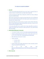
- Ravigneaux type planetary gear ratio
The Ravigneaux type planetary gear has double pinion gears for the gear ratio increasing and it is
applied in the Alpha, KM series and F4AEL-K model.
1) In the basis of point C, the rotating direction of FSG and RSG are opposite.
Also AG and RSG are opposite direction.
2) Distance from point C
Distance A - C: The ratio of forward sun gear teeth.
Distance A - B: The ratio of annulus gear teeth.
16
Chonan Technical Service Training Center
Alpha, Beta Automatic Transaxle
Distance A - D: The ratio of reverse sun gear teeth.
3) If the dot line is positioned above line A-D, it means forward rotating direction. In case of lower,
it means forward direction. Also if is positioned on the line A-D, it is a stopping state.
4) Point B, annulus gear means output of rotation.
B
(AG)
A
(FSG)
C
(Carrier)
1/74
D
(RSG)
1/34
1/26
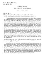
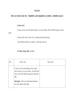
1st gear operating elements: R/C (FSG), OWC (Carrier)
A’
A(FSG)
B’
B(AG)
1/34
1/74
1/26
D(RSG)
C(Carrier)
17
Chonan Technical Service Training Center
Alpha, Beta Automatic Transaxle
1) Point C should be positioned on the line A-D, because OWC fixes the carrier.
2) FSG rotates in amount of distance from A to A’.
3) At this time AG rotates in amount of distance from B to B’.
4) RSG rotates with opposite direction comparing with FSG.
5) Using the triangle equation,
X : 1 = 1/26 : 1/74
X=2.846
X
1
1/74
1/26
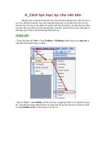
- 2nd Gear
2nd gear operating elements: R/C (FSG), K/D (RSG)
D(RSG)
1) Point D should be positioned on the line A-D, because K/D fixes the RSG.
18
Chonan Technical Service Training Center
Alpha, Beta Automatic Transaxle
2) FSG rotates in amount of distance from A to A’.
3) At this time AG rotates in amount of distance from B to B’.
4) Using the triangle equation,
X : (1/26+1/34) = 1 : (1/74+1/34)
X=1.581
X
1
1/74
1/34
1/26
- 4th Gear (Overdrive)
4th gear operating elements: E/C (Carrier), K/D (RSG)
1) Point D should be positioned on the line A-D, because K/D fixes the RSG.
2) Carrier rotates in amount of distance from C to C’.
3) At this time AG rotates in amount of distance from B to B’.
19
Chonan Technical Service Training Center
Alpha, Beta Automatic Transaxle
4) Using the triangle equation,
- Reverse Gear
Reverse gear operating elements: F/C (RSG), L&R brake (Carrier)
A(FSG)
1) Point C should be positioned on the line A-D, because L&R brake fixes the Carrier.
2) RSG rotates in amount of distance from D to D’.
3) At this time AG rotates in amount of distance from B to B’.
4) Using the triangle equation,
20
Chonan Technical Service Training Center
Alpha, Beta Automatic Transaxle
2.1.8
Parking Mechanism
When the shaft is in the “P” range, the parking pawl engages with the parking sprag provided on
outer circumference of the annulus gear to fasten the output shaft, to prevent the wheels from
rotating. In other words, when the select lever is set to the “P” range, the detent plate and the parking
sprag rod move in the direction of arrow, causing the cam on the parking sprag rod to push up the
parking pawl to engage with the sprag.
In case the parking pawl collides against a crest of the sprag, only the rod moves because the
parking pawl cannot be moved upward, and the cam, while pressing the spring, collides with the
parking pawl and the support, and is withheld in this condition. If the car is moved even slightly in this
condition, the turning of wheels causes the annulus gear to turn as well. Since the cam is pressed in
the direction of arrow, the parking pawl is pushed up as a bottom of the sprag aligns with the parking
sprag to engage with the sprag.
In this way, the parking mechanism eliminates any chances of the vehicle from being idly moved.
21
Chonan Technical Service Training Center
Alpha, Beta Automatic Transaxle
2.2 Power flow
Clutches
Selector lever position
Remarks
F/C
P
Parking
R
Reverse
N
Neutral
O/D
D
S/W
ON
Brakes
Gear position
R/C
E/C
K/D
L&R
OWC
☆□
○
○
☆
O/D
First
○
S/W
Second
○
OFF
Third
○
○
Fourth
○
○
△
○
First
○
Second
○
First
○
○
○
2
L
Notation :
☆ - Engine start possible
□ - Parking mechanism
○
○
○ - Element engaged in each gear position
△ - Pre-engaged element
For each shift condition, certain holding units in the transaxle are used. Knowing which holding
element is used and how they are connected in the transaxle, we can trace the power flow through
the transaxle for each shift condition. One set of pinions, the short pinions, meshes with the reverse
sun gear.
The other set, the long pinions, meshes with both the forward sun gear and with the annulus gear.
The two sets of pinions also mesh with each other in pairs. The pinion carrier is built as a unit with
the low reverse brake hub and the outer race of the one-way clutch. Power input is to either of the
two sun gears. The reverse sun gear is connected to the front clutch retainer through the kick-down
drum. The forward sun gear is connected to the rear clutch hub. So by engaging either the front or
the rear clutch, power is directed to either the reverse or the forward sun gear. When both front and
rear clutches are engaged, the gear set is locked, and power passes directly through the transaxle.
Power output is through the annulus gear, which has the parking sprag on the outer circumference
and is connected to the output flange.
22
Chonan Technical Service Training Center
Alpha, Beta Automatic Transaxle
- 1st Gear (“D” and “2” range)
Operating elements: Rear Clutch, One-Way Clutch
The rear clutch and one-way clutch are engaged.
Operation of rear clutch rotates the forward sun gear clockwise.
Rotation of forward sun gear moves the ring gear (annulus gear) via pinion gears.
At the moment, the planetary carrier tries to move counterclockwise because of long
pinion. However the one-way clutch holds the carrier rotation to count-clockwise, all power
is delivered to the ring gear (annulus gear).
On the contrary, power from the ring gear (annulus gear) is delivered back to the planetary
carrier. At the moment the carrier rotates clockwise loosing the power. Engine brake does
not work.
23
Chonan Technical Service Training Center
Alpha, Beta Automatic Transaxle
- 1st Gear (“L” range)
Operating elements: Rear Clutch, Low & Reverse Brake
At “L” range 1st gear, the rear clutch and low & reverse brake are engaged.
Planetary carrier is fixed.
All power is delivered to the ring gear (annulus gear) via pinion gears.
In the case that power is delivered from the ring gear back to the planetary carrier. The
carrier cannot be rotated with any direction, and the engine brake does work.
24
Chonan Technical Service Training Center
Alpha, Beta Automatic Transaxle
- 2nd Gear (“D” and “2” range)
Operating elements: Rear Clutch, Kick Down Brake
At 2nd gear the rear clutch and kick down brake are engaged.
Operation of rear clutch rotates the forward sun gear clockwise.
Rotation of forward sun gear moves the ring gear via pinion gears.
At the moment, the reverse sun gear is fixed by the kick down brake.
Long pinion gears are rotating around the sun gear. The speed of the ring gear (annulus
gear) is faster than 1st gear.
25
Chonan Technical Service Training Center