ENGINEERING DRAWING STANDARDS MANUAL
Bạn đang xem bản rút gọn của tài liệu. Xem và tải ngay bản đầy đủ của tài liệu tại đây (850.23 KB, 129 trang )
ENGINEERING DRAWING
STANDARDS MANUAL
GSFC X-673-64-1F
ENGINEERING DRAWING
STANDARDS MANUAL
S AND SPA
C
I
C
UT
E
NAL
O
TI
N
U. S. A.
INISTRA
TIO
AERO
N
M
AD
A
August 1994
NA
X-673-64-1F
Supersedes GSFC X-673-64-1E/July 1991
ENGINEERING DRAWING
STANDARDS MANUAL
Mechanical Engineering Branch
Goddard Space Flight Center
Greenbelt, Maryland
AND SPA
ICS
C
T
U
E
ON
TI
INISTRA
TIO
AL AERON
M
AD
A
August 1994
N
U. S. A.
NA
National Aeronautics and
Space Administration
Goddard Space Flight Center
Greenbelt, Maryland 20771
1994
DESCRIPTION OF REVISION
T h i s r e v i s i o n , w h i c h s u p e r s e d e s t h e G o d d ar d S p a c e F l i g h t C e n t e r ( G S F C ) S t a n d a r d
X - 6 7 3 - 6 4 - 1 E , E n g in e e r in g D r a win g S ta n d a r d s M a n u a l, is in te n d e d to u p d a te a n d r e f le c t
th e la te s t f o r ma ts a n d s ta n d a r d s a d o p te d b y G S F C.
T h e f o llo w in g is a s u mma r y o f th e p r in c ip a l c h a n g e s a n d imp r o v e me n ts in c o r p o r a te d in
this issue:
a.
A d d itio n o f Co mp o s ite Ma te r ia l D r a w in g d e f in itio n .
b . C h a n g in g o f t h e s i g n a t u r e t o a p r i n t e d n a me i n T i t l e b lo c k s .
c.
N e w e x a mp l e o f t h e M e t r i c D r a w i n g s f o r ma t a n d t o l e r a n c e p r e s e n t a t i o n .
d . I mp r o v e d p l a c e me n t o f v i e w s o n T y p e s o f D r a w i n g s s a mp l e s t o p r e v e n t u n n e c e s s a r y
r e w o r k o f d r a w in g s a t a la te r d a te .
e.
N e w E n g in e e r i n g O r d e r ( E O ) f o r ms a d d e d ; o ld E O f o r ms w i l l b e p h a s e d o u t.
f.
A d d itio n a l n o te s o n v a r io u s to p ic s a d d e d to N o te E x a mp le s s e c tio n .
g . D e le tio n o f mic r o f ilmin g r e q u ir e me n ts f o r d r a w in g f o r ma t.
h . F lo w c h a r t f o r f lig h t p r o j e c ts r e d e f in e d .
iii
iv
PREFACE
T h e G S F C E n g in e e r in g D r a win g S ta n d a r d s M a n u a l i s t h e o f f i c i a l s o u r c e f o r t h e
r e q u ir e me n ts a n d in te r p r e ta tio n s to b e u s e d in th e d e v e lo p me n t a n d p r e s e n ta tio n o f
e n g in e e r in g d r a w in g s a n d r e la te d d o c u me n ta tio n f o r th e G S F C.
T h e M e c h a n i c a l E n g i n e e r i n g B r a n c h , M e c h a n i c a l S y s t e ms D iv is io n , h a s b e e n d e le g a te d
t h e r e s p o n s i b i l i t y f o r i n t e r p r e t a t i o n , p e r i o d ic u p d a t e s , a n d d i s t r ib u t i o n o f t h e G S F C
E n g in e e r in g D r a win g S ta n d a r d s M a n u a l.
A ll E n g in e e r in g D ir e c to r a te d e s ig n o r g a n iz a tio n s a n d th e ir c o n tr a c to r s s h a ll a d h e r e to th e
r e q u ir e me n ts o f th is ma n u a l w h e n p r e p a r in g G S F C e n g in e e r in g d o c u me n ta tio n f o r f lig h t
h a r d w a r e a n d g r o u n d s u p p o r t s ys te ms .
Co mme n ts o r in q u ir ie s c o n c e r n in g th is ma n u a l s h o u ld b e d ir e c te d to th e Me c h a n ic a l
E n g in e e r in g Br a n c h , Co d e 7 2 2 .
D r . A lla n S h e r ma n
D ir e c to r o f E n g in e e r in g
v
vi
ENGINEERING DRAWING STANDARDS MANUAL
vii
TABLE OF CONTENTS
INTRODUCTION ....................................................................................................... 1
1. DRAWING ELEMENTS .......................................................................................... 3
1.1. Drawing Sizes ................................................................................................. 3
1.2. Multisheet Drawings ........................................................................................ 3
1.3. Zoning ............................................................................................................ 4
1 . 4 . T i t l e B l o c k an d R e v i s i o n B l o c k . . . . . . . . . . . . . . . . . . . . . . . . . . . . . . . . . . . . . . . . . . . . . . . . . . . . . . . . . . . . . . . . . . . . . . . . . 4
1 . 5 . D r a w i n g F o r ma t . . . . . . . . . . . . . . . . . . . . . . . . . . . . . . . . . . . . . . . . . . . . . . . . . . . . . . . . . . . . . . . . . . . . . . . . . . . . . . . . . . . . . . . . . . . . . . 1 0
2. NOMENCLATURE ................................................................................................ 11
2.1. Drawing Title ................................................................................................. 11
2.2. Abbreviations ................................................................................................. 12
2.3. List of Material .............................................................................................. 14
2 . 3 . 1 . R e q u i r e me n t s o n t h e B o d y o f t h e D r a w i n g . . . . . . . . . . . . . . . . . . . . . . . . . . . . . . . . . . . . . . . . . . . . . . . . 1 4
2 . 3 . 2 . R e q u i r e me n t s i n t h e L i s t o f M a t e r i a l . . . . . . . . . . . . . . . . . . . . . . . . . . . . . . . . . . . . . . . . . . . . . . . . . . . . . . . . 1 4
2.4. Notes on Drawings .......................................................................................... 15
2 . 4 . 1 . S e c u r i t y C l a s s i f i c at i o n . . . . . . . . . . . . . . . . . . . . . . . . . . . . . . . . . . . . . . . . . . . . . . . . . . . . . . . . . . . . . . . . . . . . . . . . . . . 1 5
2.4.2. Note Location........................................................................................ 15
2 . 4 . 3 . N u mb e r i n g o f N o t e s . . . . . . . . . . . . . . . . . . . . . . . . . . . . . . . . . . . . . . . . . . . . . . . . . . . . . . . . . . . . . . . . . . . . . . . . . . . . . . . 1 6
2 . 4 . 4 . N o t e E x a mp l e s . . . . . . . . . . . . . . . . . . . . . . . . . . . . . . . . . . . . . . . . . . . . . . . . . . . . . . . . . . . . . . . . . . . . . . . . . . . . . . . . . . . . . . 1 6
2 . 4 . 4 . 1 . D i me n s i o n N o t e s . . . . . . . . . . . . . . . . . . . . . . . . . . . . . . . . . . . . . . . . . . . . . . . . . . . . . . . . . . . . . . . . . . . . . . . . 1 6
2.4.4.2. Heat Treating Notes.................................................................... 17
2 . 4 . 4 . 3 . J o i n i n g Me t h o d N o t e s ( w e l d i n g , b r a z i n g , e t c . ) . . . . . . . . . . . . . . . . . . . . . . . . . . . . . . . 1 8
2.4.4.4. Plating and Coating Notes ........................................................... 18
2.4.4.5. Surface Preparation Notes ........................................................... 19
2.4.4.6. Testing and Inspection Notes ....................................................... 20
2.4.4.7. Threaded Inserts — Cleaning and Installation Notes ....................... 20
2.4.4.8. Miscellaneous Notes ................................................................... 21
2 . 4 . 4 . 9 . I n f o r ma t i o n a l N o t e s . . . . . . . . . . . . . . . . . . . . . . . . . . . . . . . . . . . . . . . . . . . . . . . . . . . . . . . . . . . . . . . . . . . . 2 3
2.4.5. Local Character Notes ............................................................................ 23
2 . 4 . 6 . G e n e r a l D i me n s i o n a l T o l e r a n c e N o t e s . . . . . . . . . . . . . . . . . . . . . . . . . . . . . . . . . . . . . . . . . . . . . . . . . . . . . . 2 3
2 . 5 . S p e c i f i c a t io n C a l l o u t s . . . . . . . . . . . . . . . . . . . . . . . . . . . . . . . . . . . . . . . . . . . . . . . . . . . . . . . . . . . . . . . . . . . . . . . . . . . . . . . . . . . . . 2 3
3. DRAFTING PRACTICES ....................................................................................... 25
3.1. General .......................................................................................................... 25
3.2. Lines ............................................................................................................. 25
3.2.1. Ink Lines and Plotted Lines .................................................................... 25
3.2.2. Pencil Lines .......................................................................................... 27
3.2.3. Types of Lines....................................................................................... 27
3.2.3.1. Center Lines .............................................................................. 27
3 . 2 . 3 . 2 . D i me n s i o n L i n e s . . . . . . . . . . . . . . . . . . . . . . . . . . . . . . . . . . . . . . . . . . . . . . . . . . . . . . . . . . . . . . . . . . . . . . . . 2 8
3.2.3.3. Leaders ..................................................................................... 28
3.2.3.4. Break Lines ............................................................................... 28
3.2.3.5. Phantom Lines ........................................................................... 29
3.2.3.6. Sectioning Lines ........................................................................ 29
3.2.3.7. Extension Lines ......................................................................... 30
3.2.3.8. Hidden Lines ............................................................................. 30
3.2.3.9. Stitch Lines ............................................................................... 30
3.2.3.10. Outlines or Visible Lines........................................................... 30
3.2.3.11. Datum Lines ............................................................................ 30
3 . 2 . 3 . 1 2 . C u t t i n g - P l a n e / V ie w i n g - P l a n e L i n e s . . . . . . . . . . . . . . . . . . . . . . . . . . . . . . . . . . . . . . . . . . . . 3 0
3 . 3 . L e t t e r i n g a n d N u me r a l s . . . . . . . . . . . . . . . . . . . . . . . . . . . . . . . . . . . . . . . . . . . . . . . . . . . . . . . . . . . . . . . . . . . . . . . . . . . . . . . . . . . 3 1
3.3.1. Style .................................................................................................... 31
3.3.2. Heights ................................................................................................. 32
3.4. Scale ............................................................................................................. 32
3.5. Positioning the Part on the Drawing .................................................................. 33
X-673-64-1F
G O D D AR D S P AC E F L I G H T C E N T E R , G r e e n b e l t , M a r y l a n d
viii
4.
5.
6.
7.
8.
ENGINEERING DRAWING STANDARDS MANUAL
3.5.1. Picturization ......................................................................................... 33
3.5.2. Sections ................................................................................................ 34
3.5.3. Views ................................................................................................... 36
3.5.4. Details.................................................................................................. 37
3 . 5 . 5 . I d e n t i f i c a t i o n o f S e ct i o n s , V i e w s , a n d D e t a i l s . . . . . . . . . . . . . . . . . . . . . . . . . . . . . . . . . . . . . . . . . . . 3 7
3 . 5 . 6 . L o c a t i n g S e c t i o n s, V i e w s , a n d D e t a i l s . . . . . . . . . . . . . . . . . . . . . . . . . . . . . . . . . . . . . . . . . . . . . . . . . . . . . . 3 8
TYPES OF DRAWINGS ......................................................................................... 39
4.1. Altered or Selected Vendor Part Drawing .......................................................... 39
4 . 2 . A s s e mb l y D r a w i n g . . . . . . . . . . . . . . . . . . . . . . . . . . . . . . . . . . . . . . . . . . . . . . . . . . . . . . . . . . . . . . . . . . . . . . . . . . . . . . . . . . . . . . . . . . 4 0
4.3. Detail Drawing ............................................................................................... 41
4.4. Drawing Tree ................................................................................................. 42
4 . 5 . E l e c t r i c a l / E l e c tr o n i c D r a w i n g s . . . . . . . . . . . . . . . . . . . . . . . . . . . . . . . . . . . . . . . . . . . . . . . . . . . . . . . . . . . . . . . . . . . . . . . . . 4 3
4 . 5 . 1 . E l e c t r i c a l a n d E l e c t r o n i c S y mb o l s . . . . . . . . . . . . . . . . . . . . . . . . . . . . . . . . . . . . . . . . . . . . . . . . . . . . . . . . . . . . 4 3
4 . 5 . 2 . E l e c t r i c a l a n d E l e c t r o n i c D i a g r a ms . . . . . . . . . . . . . . . . . . . . . . . . . . . . . . . . . . . . . . . . . . . . . . . . . . . . . . . . . . 4 3
4 . 6 . I n s e p a r a b l e A s s e mb l y D r a w i n g . . . . . . . . . . . . . . . . . . . . . . . . . . . . . . . . . . . . . . . . . . . . . . . . . . . . . . . . . . . . . . . . . . . . . . . . . 4 4
4 . 7 . I n s t a l l a t i o n A s s e mb l y D r a w i n g . . . . . . . . . . . . . . . . . . . . . . . . . . . . . . . . . . . . . . . . . . . . . . . . . . . . . . . . . . . . . . . . . . . . . . . . . 4 5
4.8. Interface Control Drawing ............................................................................... 46
4.9. Matched-Set Drawing ...................................................................................... 48
4 . 1 0 . M e c h a n i c a l S c h e ma t i c . . . . . . . . . . . . . . . . . . . . . . . . . . . . . . . . . . . . . . . . . . . . . . . . . . . . . . . . . . . . . . . . . . . . . . . . . . . . . . . . . . . . 4 9
4.11. Modification Drawing .................................................................................... 51
4.12. Outline Drawing ........................................................................................... 51
4.13. Source Control Drawing ................................................................................. 53
4 . 1 4 . S p e c i f i c a t i o n Co n t r o l D r a w i n g . . . . . . . . . . . . . . . . . . . . . . . . . . . . . . . . . . . . . . . . . . . . . . . . . . . . . . . . . . . . . . . . . . . . . . . . 5 4
4.15. Standard Part Drawing ................................................................................... 56
4.16. Tabulated Drawing ........................................................................................ 56
4.17. Tooling Drawing ........................................................................................... 57
4 . 1 8 . C o mp o s i t e M a t e r i a l D r a w i n g . . . . . . . . . . . . . . . . . . . . . . . . . . . . . . . . . . . . . . . . . . . . . . . . . . . . . . . . . . . . . . . . . . . . . . . . . . 5 8
NUMBERING SYSTEM FOR DRAWINGS AND SUPPORTING DOCUMENTATION . 60
5 . 1 . P a r t N u mb e r i n g . . . . . . . . . . . . . . . . . . . . . . . . . . . . . . . . . . . . . . . . . . . . . . . . . . . . . . . . . . . . . . . . . . . . . . . . . . . . . . . . . . . . . . . . . . . . . . 6 1
5 . 2 . F i n d o r I t e m N u mb e r i n g . . . . . . . . . . . . . . . . . . . . . . . . . . . . . . . . . . . . . . . . . . . . . . . . . . . . . . . . . . . . . . . . . . . . . . . . . . . . . . . . . . . 6 2
5.3. Order of Precedence of Specifications and Standards .......................................... 62
5.3.1. Group I ................................................................................................. 62
5.3.2. Group II ............................................................................................... 62
5.3.3. Group III .............................................................................................. 63
5.3.4. Group IV .............................................................................................. 63
5.3.5. Group V................................................................................................ 63
ENGINEERING ORDER ........................................................................................ 64
6 . 1 . G e n e r a l R e q u i r e me n t s . . . . . . . . . . . . . . . . . . . . . . . . . . . . . . . . . . . . . . . . . . . . . . . . . . . . . . . . . . . . . . . . . . . . . . . . . . . . . . . . . . . . . . 6 4
6 . 2 . F o r ma t S a mp l e . . . . . . . . . . . . . . . . . . . . . . . . . . . . . . . . . . . . . . . . . . . . . . . . . . . . . . . . . . . . . . . . . . . . . . . . . . . . . . . . . . . . . . . . . . . . . . . . 6 4
DRAWING REVISIONS ......................................................................................... 68
7 . 1 . R e v i s i o n Me t h o d s . . . . . . . . . . . . . . . . . . . . . . . . . . . . . . . . . . . . . . . . . . . . . . . . . . . . . . . . . . . . . . . . . . . . . . . . . . . . . . . . . . . . . . . . . . . 6 8
7.2. Revision Identification .................................................................................... 68
7.3. Revision of Multisheet Drawings ...................................................................... 68
7.4. Revision Recording ......................................................................................... 68
7.5. Redrawn or Replaced Drawings ........................................................................ 70
PARTS LIST AND INDEX LIST ............................................................................. 71
8.1. Definitions ..................................................................................................... 71
8 . 2 . R e q u i r e me n t s . . . . . . . . . . . . . . . . . . . . . . . . . . . . . . . . . . . . . . . . . . . . . . . . . . . . . . . . . . . . . . . . . . . . . . . . . . . . . . . . . . . . . . . . . . . . . . . . . . 7 1
8.2.1. List Preparation ..................................................................................... 71
8 . 2 . 2 . L i s t F o r ma t s . . . . . . . . . . . . . . . . . . . . . . . . . . . . . . . . . . . . . . . . . . . . . . . . . . . . . . . . . . . . . . . . . . . . . . . . . . . . . . . . . . . . . . . . . . 7 2
8.2.3. Revision Identification ........................................................................... 72
8 . 2 . 4 . D e l e t i n g I t e ms . . . . . . . . . . . . . . . . . . . . . . . . . . . . . . . . . . . . . . . . . . . . . . . . . . . . . . . . . . . . . . . . . . . . . . . . . . . . . . . . . . . . . . . 7 2
8 . 2 . 5 . A d d i n g I t e ms . . . . . . . . . . . . . . . . . . . . . . . . . . . . . . . . . . . . . . . . . . . . . . . . . . . . . . . . . . . . . . . . . . . . . . . . . . . . . . . . . . . . . . . . . 7 2
8.3. Cover Sheet.................................................................................................... 72
8 . 3 . 1 . F o r ma t . . . . . . . . . . . . . . . . . . . . . . . . . . . . . . . . . . . . . . . . . . . . . . . . . . . . . . . . . . . . . . . . . . . . . . . . . . . . . . . . . . . . . . . . . . . . . . . . . . 7 2
X-673-64-1F
G O D D AR D S P AC E F L I G H T C E N T E R , G r e e n b e l t , M a r y l a n d
ENGINEERING DRAWING STANDARDS MANUAL
ix
8.3.2. Entries.................................................................................................. 72
8 . 4 . P a r t s L i s t Co n t i n u a t i o n S h e e t . . . . . . . . . . . . . . . . . . . . . . . . . . . . . . . . . . . . . . . . . . . . . . . . . . . . . . . . . . . . . . . . . . . . . . . . . . . 7 5
8 . 4 . 1 . F o r ma t . . . . . . . . . . . . . . . . . . . . . . . . . . . . . . . . . . . . . . . . . . . . . . . . . . . . . . . . . . . . . . . . . . . . . . . . . . . . . . . . . . . . . . . . . . . . . . . . . . 7 5
8.4.2. Entries.................................................................................................. 75
8 . 5 . I n d e x L i s t Co n t i n u a t i o n S h e e t . . . . . . . . . . . . . . . . . . . . . . . . . . . . . . . . . . . . . . . . . . . . . . . . . . . . . . . . . . . . . . . . . . . . . . . . . . 7 7
8 . 5 . 1 . F o r ma t . . . . . . . . . . . . . . . . . . . . . . . . . . . . . . . . . . . . . . . . . . . . . . . . . . . . . . . . . . . . . . . . . . . . . . . . . . . . . . . . . . . . . . . . . . . . . . . . . . 7 7
8.5.2. Entries.................................................................................................. 77
8 . 6 . F i n d o r I t e m N u mb e r S ys t e m o f I d e n t i f i c a t i o n . . . . . . . . . . . . . . . . . . . . . . . . . . . . . . . . . . . . . . . . . . . . . . . . . . . . 7 9
8.6.1. Definition ............................................................................................. 79
8 . 6 . 2 . A p p l i c a t i o n a n d L i mi t a t i o n . . . . . . . . . . . . . . . . . . . . . . . . . . . . . . . . . . . . . . . . . . . . . . . . . . . . . . . . . . . . . . . . . . . . . 7 9
8 . 6 . 3 . D r a w i n g R e q u i r e me n t s . . . . . . . . . . . . . . . . . . . . . . . . . . . . . . . . . . . . . . . . . . . . . . . . . . . . . . . . . . . . . . . . . . . . . . . . . . . 8 0
8.7. List of Material .............................................................................................. 81
8 . 7 . 1 . F o r ma t . . . . . . . . . . . . . . . . . . . . . . . . . . . . . . . . . . . . . . . . . . . . . . . . . . . . . . . . . . . . . . . . . . . . . . . . . . . . . . . . . . . . . . . . . . . . . . . . . . 8 1
8.7.2. Entries.................................................................................................. 81
9. DOCUMENTATION MANAGEMENT ..................................................................... 82
9.1. Typical Drawing Flow for Flight Projects .......................................................... 82
9.2. Archiving....................................................................................................... 83
9 . 3 . C o mp u t e r - A i d e d D e s i g n D r a w i n g s . . . . . . . . . . . . . . . . . . . . . . . . . . . . . . . . . . . . . . . . . . . . . . . . . . . . . . . . . . . . . . . . . . . . 8 3
9 . 3 . 1 . P r e s e n t a t i o n o f C o mp u t e r - G e n e r a t e d D a t a . . . . . . . . . . . . . . . . . . . . . . . . . . . . . . . . . . . . . . . . . . . . . . . . . 8 3
9 . 3 . 2 . D e v e l o p i n g a n d U s i n g C o mp u t e r - G e n e r a t e d D r a w i n g s . . . . . . . . . . . . . . . . . . . . . . . . . . . . . . . . 8 4
9.3.3. Specification Data ................................................................................. 84
1 0 . D E S I G N R E F E R E N C E S , S TA N D A R D S , A N D S P E C I F I C A T I O N S . . . . . . . . . . . . . . . . . . . . . . . . . . . 8 5
1 0 . 1 . D i me n s i o n i n g a n d T o l e r a n c i n g . . . . . . . . . . . . . . . . . . . . . . . . . . . . . . . . . . . . . . . . . . . . . . . . . . . . . . . . . . . . . . . . . . . . . . . . 8 5
1 0 . 1 . 1 . D i me n s i o n i n g a n d T o l e r a n c i n g P r a c t i c e s . . . . . . . . . . . . . . . . . . . . . . . . . . . . . . . . . . . . . . . . . . . . . . . . . 8 5
1 0 . 1 . 2 . S t a t e me n t s o n D i me n s i o n i n g . . . . . . . . . . . . . . . . . . . . . . . . . . . . . . . . . . . . . . . . . . . . . . . . . . . . . . . . . . . . . . . . . . 8 5
1 0 . 2 . M e t r i c D i me n s i o n i n g . . . . . . . . . . . . . . . . . . . . . . . . . . . . . . . . . . . . . . . . . . . . . . . . . . . . . . . . . . . . . . . . . . . . . . . . . . . . . . . . . . . . . 8 6
1 0 . 2 . 1 . S I U n i t s a n d S y mb o l s . . . . . . . . . . . . . . . . . . . . . . . . . . . . . . . . . . . . . . . . . . . . . . . . . . . . . . . . . . . . . . . . . . . . . . . . . . . 8 6
10.2.2. Unit Conversions ................................................................................. 89
1 0 . 2 . 2 . 1 . C o n v e r s i o n o f D i me n s i o n s . . . . . . . . . . . . . . . . . . . . . . . . . . . . . . . . . . . . . . . . . . . . . . . . . . . . . . . . . 8 9
10.2.2.2. Unit Rounding.......................................................................... 89
10.3. Design References ......................................................................................... 92
10.4. Control of Surface Roughness......................................................................... 93
10.4.1. Surface Texture ................................................................................... 93
1 0 . 4 . 2 . S u r f a c e T e x t u r e S y mb o l s . . . . . . . . . . . . . . . . . . . . . . . . . . . . . . . . . . . . . . . . . . . . . . . . . . . . . . . . . . . . . . . . . . . . . . 9 3
10.4.3. Surface Texture Standards..................................................................... 93
10.5. Thread Specifications .................................................................................... 93
10.6. Welding—Fusion and Resistance ..................................................................... 95
10.6.1. General ............................................................................................... 95
1 0 . 6 . 2 . B a s i c W e l d S y mb o l s a n d T h e i r L o c a t i o n S i g n i f i c a n c e . . . . . . . . . . . . . . . . . . . . . . . . . . . . . . 9 5
10.7. Outgassing of Spacecraft Materials ................................................................. 95
10.8. Standards and Specifications Index ................................................................. 96
10.8.1. National Bureau of Standards ................................................................ 96
10.8.2. Federal ............................................................................................... 96
10.8.3. Industrial ............................................................................................ 97
10.8.4. Military .............................................................................................. 98
10.8.5. NASA ............................................................................................... 100
1 0 . 9 . S t a n d a r d s a n d S p e c i f i c at i o n s N u me r i c a l I n d e x . . . . . . . . . . . . . . . . . . . . . . . . . . . . . . . . . . . . . . . . . . . . . . . . 1 0 1
A P P E N D I X A . D E S I G N R EV I E W D O s A N D D O N ' T s . . . . . . . . . . . . . . . . . . . . . . . . . . . . . . . . . . . . . . . . . . . . . . . . 1 0 7
INDEX.................................................................................................................... 110
X-673-64-1F
G O D D AR D S P AC E F L I G H T C E N T E R , G r e e n b e l t , M a r y l a n d
x
X-673-64-1F
ENGINEERING DRAWING STANDARDS MANUAL
G O D D AR D S P AC E F L I G H T C E N T E R , G r e e n b e l t , M a r y l a n d
ENGINEERING DRAWING STANDARDS MANUAL
1
INTRODUCTION
T h is d r a w in g s ta n d a r d s ma n u a l e s ta b lis h e s th e c o n v e n tio n s to b e a d h e r e d to b y
e n g in e e r in g a n d d r a f tin g p e r s o n n e l in th e p r e p a r a tio n , r e v is io n , a n d c o mp le tio n o f
e n g i n e e r i n g d r a w i n g s . T h i s ma n u a l s e t s f o r t h t h e min i mu m r e q u i r e me n t s a c c e p t a b l e a t
G S F C f o r th e p r e p a r a tio n o f e n g in e e r in g d r a w in g s f o r f lig h t h a r d w a r e a n d g r o u n d
s u p p o r t s ys te ms . T h e r e q u ir e me n ts s p e c if ie d h e r e in a r e e s s e n tia l to th e s ta n d a r d iz a tio n
o f p r a c tic e s a n d to a u n if o r m in te r p r e ta tio n o f d r a w in g s .
A s ys te m, p a ylo a d , o r c o mp o n e n t a s s e mb ly s h a ll b e c o mp le te ly d e f in e d b y me a n s o f
d r a w in g s , in c lu d in g lis ts , s c h e ma tic s , w ir in g d ia g r a ms , a n d s p e c if ic a tio n s , to e n s u r e th a t
c o mp o n e n t s f a b r i c a t e d a r e i n a c c o r d a n c e w i t h t h e d e s i g n . T h e d o c u me n t a t i o n
i n f o r ma t i o n s h a l l s e r v e a s a p e r ma n e n t r e c o r d .
F l i g h t h a r d w a r e s h a l l b e f a b r i c a t e d i n a c c o r d a n c e w i t h t h e a p p r o v e d d e s i g n d o c u me n t s .
T h e s e d o c u me n t s s h a l l r e f l e c t t h e c h a r a c t e r i s t i c s a n d a c c e p t a n c e c r i t e r i a f o r a l l
ma t e r i a l s , c o mp o n e n t / p a r t s , s u b s y s t e ms , a n d t h e c o mp l e t e s y s t e m. T h e a c c e p t a n c e
c r i t e r i a f o r p a r t s a n d ma t e r i a l s s h a l l b e s pe c i f i e d b y s t a n d a r d s p e c i f i c a t i o n s w h e n
applicable.
E n g in e e r in g d r a w in g s a r e d e f in e d a s th o s e d r a w in g s th a t c o mmu n ic a te th e r e q u ir e me n ts
f o r th e ma n u f a c tu r e o f th e e n d - p r o d u c t ite ms , th e ir a s s e mb ly, a n d th e ir in s ta lla tio n in th e
e n d p r o d u c t.
T h e e n g in e e r in g d r a w in g s p r e p a r e d b y G S F C d e s ig n p e r s o n n e l o r c o n tr a c to r s o n G S F C
d r a w in g f o r ma t u s in g G S F C d r a w in g n u mb e r s s h a ll b e k n o w n a s “ G o v e r n me n t D e s ig n
A c tiv ity D r a w in g s . ” P a r ts ma d e to th e s e d r a w in g s typ ic a lly w o u ld b e ma n u f a c tu r e d
th r o u g h th e F a b r ic a tio n E n g in e e r in g Br a n c h , E n g in e e r in g S e r v ic e s D iv is io n , G S F C.
“ C o n t r a c t o r D e s i g n A c t i v i t y D ra w i n g s ” ” ” ” ( w h i c h a r e a c o mp a n y 's d r a w i n g s b e a r i n g t h e
c o mp a n y n a me , a d d r e s s , f e d e r a l c o d e id e n tif ic a tio n , a n d d r a w in g n u mb e r ) s h o u ld b e u s e d
w h e n t h e c o mp a n y i s d e s i g n i n g a n d d e l i v e r in g t h e f i n i s h e d p r o d u ct i n a c c o r d a n c e w i t h
t h e t e r ms o f a N A S A c o n t r a c t .
The Design Activity shall be defined as an activity having responsibility for the design
o f a n i t e m o r s y s t e m. T h e a c t i v i t y ma y b e a g o v e r n me n t e n t i t y , a c o n t r a c t o r , a v e n d o r , o r
a n o th e r o r g a n iz a tio n s u c h a s a u n iv e r s ity.
A l t h o u g h g e n e r a l l y i n a c c o r d a n c e w i t h t h e D e p ar t me n t o f D e f e n s e a n d i n d u s t r y p r a c t i c e s
a n d p r o c e d u r e s , th is d r a w in g s ta n d a r d s man u a l d o e s c o n ta in s p e c if ic d if f e r e n c e s a n d
e x c e p t i o n s t o E n g in e e r in g D r a win g P r a c tic e s, MI L - S T D - 1 0 0 E . T h is ma n u a l, w h ile n o t
in te n d e d a s a ma n u a l o f in s tr u c tio n in th e b a s ic p r in c ip le s o f d r a f tin g , d o e s s e t f o r th th e
min i mu m r e q u i r e me n t s a c c e p t a b l e a t t h e G S F C. O n e o f t h o s e r e q u i r e me n t s i s t h a t
p e r s o n s e n g a g e d in th e p r e p a r a tio n o f d r a w in g s s h a ll h a v e a th o r o u g h u n d e r s ta n d in g o f
th e f u n d a me n ta ls o f d r a f tin g a n d g e o me tr ic a l d ime n s io n in g a n d to le r a n c in g ( in
a c c o r d a n c e w i t h A N S I Y 1 4 . 5 M - 1 9 8 2 , D im e n s io n in g a n d T o le r a n c in g ) in o r d e r to
p r o d u c e in te r p r e ta b le d r a w in g s .
X-673-64-1F REV 001 DEC. ‘94
G O D D AR D S P AC E F L I G H T C E N T E R , G r e e n b e l t , M a r y l a n d
2
ENGINEERING DRAWING STANDARDS MANUAL
X-673-64-1F REV 001 DEC. ‘94
G O D D AR D S P AC E F L I G H T C E N T E R , G r e e n b e l t , M a r y l a n d
ENGINEERING DRAWING STANDARDS MANUAL
1.
DRAWING ELEMENTS
1.1.
Drawing Sizes
3
T h e f o llo w in g ta b le d e f in e s th e s ta n d a r d d r a w in g s iz e s , a n d th e ir le tte r
d e s ig n a tio n s to b e u s e d a t G S F C:
Letter
Designation
B
C
D
E
F
J
Sheet Width
(inches)
11
17
22
34
28
34
Sheet Length
(inches)
17
22
34
44
40
48 to 144(a)
Margin
(inches)
3/8
1/2
1/2
1/2
1/2
1/2(b)
Notes:
( a ) L e n g th s f o r “ J ” r o l l s i z e t o b e i n l l - i n c h i n c r e me n t s .
( b ) N o t in c lu s iv e o f a d d e d p r o te c tiv e ma r g in s o f a t le a s t 2 in c h e s o n b o th e n d s o f
roll size drawings.
1.2.
Multisheet Drawings
M u l t i s h e e t d r a w i n g s a r e p e r mi t t e d i n a l l s i z e s .
a . T h e f i r s t s h e e t o f a mu l t i s h e e t d r a w i n g s h a l l a l w a y s c o n ta i n t h e c o mp l e t e T i t l e
b lo c k , L is t o f Ma te r ia l, Re v is io n Blo c k , a n d g e n e r a l n o te s .
b . A l l s h e e t s o f mu l t i s h e e t d r a w i n g s s h a l l b e o f t h e s a me l e t t e r s i z e . U s e o f
mu l t i s h e e t d r a w i n g s s h a l l b e f o u n d t o b e a d v a n t a g e o u s f o r c e r t a i n t y p e s o f
s c h e ma tic s a n d d ia g r a ms .
c.
T h e s h e e ts o f “ J ” s iz e d r a w in g s ma y b e a n y o f th e a b o v e - n o te d le n g th s a n d
ma y b e in te r mix e d in d if f e r e n t le n g th s .
d . S h e e t n u mb e r in g f o r a ll f ir s t s h e e ts s h a ll in c lu d e th e to ta l n u mb e r o f s h e e ts ,
a s “ S H E E T 1 O F 1 , ” “ S H E E T 1 O F 2 , ” e tc . N u mb e r i n g o f c o n t i n u a t i o n s h e e t s
s h a l l b e l i mi t e d t o s t a t i n g t h e s p e c i f i c s h e e t n u mb e r ( e . g . , “ S H E E T 2 , ”
“ S H E E T 3 ” ) w i t h o u t s p e c i f y i n g t h e t o t a l n u mb e r o f s h e e t s .
X-673-64-1F REV 001 DEC. ‘94
G O D D AR D S P AC E F L I G H T C E N T E R , G r e e n b e l t , M a r y l a n d
4
ENGINEERING DRAWING STANDARDS MANUAL
1.3.
Zoning
V e r tic a l a n d h o r iz o n ta l z o n in g ma y b e u s e d if n e c e s s a r y to p r o v id e o r ie n ta tio n to
t h e f i e l d o f d r a w i n g s . Z o n in g i s ma n d a t o r y f o r mu l t i s h e e t d r a w i n g s “ D ” s i z e a n d
l a r g e r a n d s i n g l e - s h e e t d r a w i n g s “ E ” s i z e an d l a r g e r . Z o n e s s h a l l b e i d e n t i f i e d b y
a l p h a b e t i c a l ( u p p e r c a s e ) a n d n u me r i c a l e n t r i e s i n t h e mar g i n s p a c e s a s i n d i c a t e d
in F ig u r e 1 . Z o n e s iz e s s h a ll b e 8 ½ in c h e s ( w id th ) b y 1 1 in c h e s ( le n g th ) f o r “ E ”
and “J” size, 7 inches (width) by 10 inches (length) for “F” size, and 5½ inches
(width) by 8½ inches (length) for “D” size.
SECURITY CLASSIFICATION
5
3
4
2
1
D
C
VERTICAL ZONE IDENTIFICATION
ALPHABETICALLY LETTERED
FROM BOTTOM EDGE
D
ALTERNATE
LOCATION OF
GENERAL NOTES
C
B
B
DRAWING NUMBER ON REVERSE
SIDE FOR ROLL-SIZE DRAWINGS
PREFERRED
LOCATION OF
GENERAL NOTES
APPROX. 2-INCH ADDITIONAL MARGIN
FOR PROTECTION OF ROLL-SIZE DRAWINGS
HORIZONTAL ZONE
IDENTIFICATION NUMBERED
FROM RIGHT-HAND EDGE
APPROX. 2-INCH ADDITIONAL MARGIN
FOR PROTECTION OF ROLL-SIZE DRAWINGS
DRAWING NUMBER ON REVERSE
SIDE FOR ROLL-SIZE DRAWINGS
REVISION NOTES
SECURITY NOTATION (IF REQUIRED)
A
TITLE BLOCK
5
4
3
2
A
1
SECURITY CLASSIFICATION
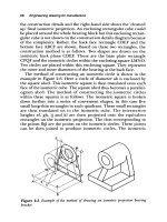
Figure 1: Format for B, C, D, E, F, and J Size Drawings
1.4.
Title Block and Revision Block
T i t l e b lo c k s a n d r e v is i o n b lo c k s s h a l l b e p r e p a r e d a n d c o mp l e t e d a s f o l l o w s :
T h e T i t l e b lo c k o f s i n g le - s h e e t d r a w i n g s , f i r s t s h e e t s o f mu l t i s h e e t d r a w i n g s , a n d
r e v is io n b lo c k s s h a ll a p p e a r a s s h o w n in e ith e r F ig u r e 2 a o n p a g e 5 ( d ime n s io n a l
s y s t e m/ i n c h e s ) o r F i g u r e 2 b o n p a g e 6 ( d i me n s i o n a l s y s t e m/ mi l l i me t e r s ) . T h e
i n f o r ma t i o n r e q u ir e d i n t h e T i t l e b lo c k s h a l l b e a s s p e c i f i e d o r r e f e r e n c e d b y
i t e ms 1 t h r o u g h 2 8 , b e l o w . T h e T i t l e b lo c k o f c o n t i n u a t i o n s h e e t s f o r mu l t i s h e e t
d r a w in g s s h a ll c o n ta in in f o r ma tio n lis te d in ite ms 1 , 2 , a n d 4 th r o u g h 1 1 .
X-673-64-1F REV 001 DEC. ‘94
G O D D AR D S P AC E F L I G H T C E N T E R , G r e e n b e l t , M a r y l a n d
5
ENGINEERING DRAWING STANDARDS MANUAL
REVISION
ZONE
25
DATE
26
APPROVAL
27
28
FOLD
24
DESCRIPTION
LINE
SYM
REV
24
1
13
15
19
18
10
9
8
20
7
6
21
5
3
4
2
23
22
GD
14
11
12
REQD
ITEM
REQD
PART NO.
MATERIAL
DESCRIPTION
NO
MATERIAL SPEC & NO.
LIST OF MATERIAL
UNLESS OTHERWISE SPECIFIED - DIMENSIONS ARE IN INCHES
NATIONAL AERONAUTICS AND
TOLERANCES:
.XX
±.02
±.005
Goddard Space Flight Center
SPACE ADMINISTRATION
.XXX
FRACTIONS
±1°
125
NAME
±1/16
INIT
GREENBELT, MARYLAND
DATE
DRAWING INTERPRETED PER GSFC-X673-64-1
DESIGNER
REMOVE ALL BURRS AND SHARP EDGES R .010 OR CHAMFER MAX.
FLIGHT HARDWARE/POST FAB HARDNESS TEST REQ'D
HARDNESS TEST NOT REQUIRED
16
DRAWN
TITLE
NON FLIGHT
TEST HARDNESS PER ASTM E-18, LOCATION OPTIONAL
CHECKED
TEST HARDNESS PER ASTM E-18 WHERE INDICATED
APPROVED
ON FIELD OF DRAWING THUS
NO NON-DESTRUCTIVE EXAMINATION (NDE) REQ'D
APPROVED
NDE REQUIRED PER S-313-009 CODE
APPROVED-STRESS
THIS DRAWING WAS PRODUCED USING
SOFTWARE:
VERSION:
REV
GD
APPROVED-ENGINEER
NEXT ASSY
FILE NAME:
USED ON
CODE
SCALE
WT.
SH
FOLD
LINE
Figure 2a: Sample “Title and Revision Block” (Enlarged View)
for Dimensional System/Inches
X-673-64-1F REV 001 DEC. ‘94
G O D D AR D S P AC E F L I G H T C E N T E R , G r e e n b e l t , M a r y l a n d
6
ENGINEERING DRAWING STANDARDS MANUAL
REVISION
DESCRIPTION
ZONE
25
26
APPROVAL
27
28
FOLD
24
DATE
LINE
SYM
REV
24
1
13
15
19
18
16
10
9
20
8
7
6
5
21
3
4
2
24
23
22
GD
14
11
12
17
ITEM
REQD
REQD
PART NO
DESCRIPTION
NO
MATERIAL
MATERIAL SPEC & NO
LIST OF MATERIAL
FLIGHT HARDWARE/POST FAB HARDNESS TEST REQ'D
METRIC
NATIONAL AERONAUTICS AND
SPACE ADMINISTRATION
NAME
TEST HARDNESS PER ASTM E-18, LOCATION OPTIONAL
HYBRID
Goddard Space Flight Center
INIT
DATE
DRAWING INTERPRETED PER GSFC-X673-64-1
TEST HARDNESS PER ASTM E-18 WHERE INDICATED
METRIC/INCH
GREENBELT, MARYLAND
NON FLIGHT
HARDNESS TEST NOT REQUIRED
DESIGNER
ON FIELD OF DRAWING THUS
THIRD ANGLE PROJECTION
NON-DESTRUCTIVE EXAMINATION (NDE) NOT REQD
DRAWN
TITLE
NDE REQUIRED PER S-313-009 CODE
CHECKED
UNLESS OTHERWISE SPECIFIED
DIMENSION ARE IN MM
THIS DRAWING WAS PRODUCED USING
SOFTWARE:
DIMENSION TOLERANCES
3.2
2 DECIMAL
±0.25
1 DECIMAL
MECHANICAL ENGINEER
VERSION:
FILE NAME:
SYSTEMS ENGINEER
±0.5
FINISH
DECIMAL
±1
IN
ANGLE
±1°
MICRO-
RAD/CHAM
±0.5
METERS
REV
ELECTRICAL ENGINEER
GD
STRESS ENGINEER
REMOVE ALL BURRS AND SHARP
NEXT ASSY
USED ON
CODE
SCALE
WT
SH
LINE
FOLD
EDGES R 0.25 OR CHAMFER MAX
Figure 2b: Sample “Title and Revision Block” (Enlarged View)
for Dimensional System/Millimeters
X-673-64-1F REV 001 DEC. ‘94
G O D D AR D S P AC E F L I G H T C E N T E R , G r e e n b e l t , M a r y l a n d
ENGINEERING DRAWING STANDARDS MANUAL
1
DRAWING NO.: See page 60.
2
“SH
OF
on sheet 1.
3
W T : E n te r u n it w e ig h t c a lc u la te d a t time o f d e s ig n if r e q u ir e d .
4
T I T L E : S e e p a r a g r a p h 2 . 1 o n p a g e 1 1 f o r s e le c tio n a n d a r r a n g e me n t o f
drawing title. See paragraph 3.3.2 on page 32 for drawing title size.
5
S C A L E : E n te r s c a le . S e e p a r a g r a p h 3 . 4 o n p a g e 3 2 f o r s e le c tio n o f s c a le .
6
CODE: For drawings prepared by the Goddard Space Flight Center (GSFC)
w ith a n o f f ic ia l G S F C d r a w in g n u mb e r , e n te r th e th r e e - d ig it G S F C c o d e
id e n tif yin g th e g r o u p r e s p o n s ib le f o r th e d r a w in g .
7
” : E n t e r s h e e t n u mb e r a s a p p l ic a b l e . I n d i c a t e t o t a l s h e e t s o n l y
F o r d r a w in g s p r e p a r e d b y a c o n tr a c to r w ith a c o n tr a c to r d r a w in g n u mb e r a n d
f o r ma t, th e c o n tr a c to r 's c o d e n u mb e r f r o m th e Co mme r c ia l a n d G o v e r n me n t
E n t i t y ( C A G E ) P u b l i c a t i o n H 4 / H 8 ( f o r me r l y F e d e r a l S u p p ly Co d e fo r
M a n u fa c tu r e r s ( F S C M ) H 4 a n d F e d e r a l S u p p ly Co d e s fo r No n - M a n u fa c tu r e r s
( F S C N M) H 8 ) s h a l l a p p e a r .
7
DATE: Enter date of initials.
8
D E S I G N E R : E n t e r d e s i g n e r ' s p r i n t e d n a me a n d i n i t i a l s .
9
D R A W N : E n te r d r a f ts ma n 's p r in te d n a me o r if d r a w n b y th e d e s ig n e r , th e
d e s ig n e r ’ s p r in te d n a me ma y b e r e p e a te d .
1 0 C H E C K E D : E n t e r d e s i g n a n a l y s t ' s p r i n t e d n a me . T h i s n a me s h a l l b e a n
in d e p e n d e n t n a me f r o m a ll o th e r n a me s o n th e d r a w in g . I t r e p r e s e n ts th a t th e
d r a w in g h a s b e e n c h e c k e d a g a in s t th e p a r a me te r s o f th is d r a w in g ma n u a l a n d ,
w h e r e p o s s i b le , t o f o r m, f i t , f u n c t i o n , a n d f e a s i b i l i t y . T h e c h e c k e r mu s t h a v e
a th o r o u g h u n d e r s ta n d in g o f th e me th o d s a n d p r a c tic e s o f g e o me tr ic
tolerancing and be able to specify such practices in accordance with ANSI
S ta n d a r d Y 1 4 . 5 M- 1 9 8 2 , D im e n s io n in g a n d T o le r a n c in g .
1 1 A P P R O V E D : E n te r th e p r in te d n a me s o f G S F C p e r s o n n e l a s s ig n e d to a p p r o v e
th e d r a w in g . P r o j e c t r e q u ir e me n ts f o r d r a w in g n a me s s h a ll v a r y f r o m p r o g r a m
t o p r o g r a m, b u t e a c h n a me s h a l l b e i d e n t i f i e d . F o r e x a mp l e , a f t e r e a c h
a p p r o v a l n a me , n o te th e f o llo w in g : “ E N G ” f o r e n g in e e r , “ S T RE S S ” f o r s tr e s s
e n g in e e r , “ Q A ” f o r q u a l i t y a s s u r a n c e e n g in e e r , “ M A T L ” f o r ma t e r i a l s
e n g i n e e r , “ E L E C ” f o r e l e c t r ic a l e n g i n e e r , e t c . A l l n a me s i n l i n e i t e ms 8
t h r o u g h 1 1 mu s t b e l e g i b l e . T h e h a n d -w r i t t e n i n i t i a l s o n t h e p a p e r o r i g i n a l
a r e t h e o f f i c i a l a p p r o v a l o f t h a t d o c u me n t .
1 2 U S E D O N : E n te r a c r o n ym n a me o f p r o g r a m a n d a c r o n ym n a me o f s u b s ys te m
o r e x p e r ime n t w h e r e a p p lic a b le .
X-673-64-1F REV 001 DEC. ‘94
G O D D AR D S P AC E F L I G H T C E N T E R , G r e e n b e l t , M a r y l a n d