Construction projectconstruction
Bạn đang xem bản rút gọn của tài liệu. Xem và tải ngay bản đầy đủ của tài liệu tại đây (1.86 MB, 91 trang )
Final year project
LAPAZ Tower
PART 3
CONSTRUCTION
(45%)
INTRUCTOR: VUONG DO TUAN CUONG
STUDENT : NGUYEN DUC DUY
CLASS
: 56XE
ID
:5655.56
TASK:
Nguyen Duc Duy-565556-56XE
1
Final year project
LAPAZ Tower
CHAPTER I. INTRODUCTION OF CONSTRUCTION METHOD
I.1 PROJECT INFOMATION
I.1.1 Location
Project name:
Investor:
Location:
LAPAZ Tower
Danang Housing investment development joint stock company
38 Nguyen Chi Thanh, Thach Thang, Hai Chau district, Da Nang
city
Floor count:
19
Land area:
1000m2
Constructed area: 784m2
Floor area:
11232m2
North, South and East sides of the building are near residential areas.
West side is adjacent to Nguyen Chi Thanh Street.
I.1.2 Building structure
1) Foundation
Foundation system of the project includes:
Bored pile D1000: 66 piles.
Height of pile cap: h = 1.5 (m)
Tie beam: b x h = 500 x 700 (mm)
Because the elevation of pile top is not too deep from natural ground level and being
convenient for construction, bored piles will be constructed from the elevation of the
natural ground. The concrete level of bored pile is 1m beyond the pile cap bottom.
Afterwards, sand will be filled into the bored hole to natural ground level.
2) Basements
In this project, the building has 2 basements with the total depth of 6.4m from the
elevation of first floor and 4.4m from the natural ground level. Larssen sheet pile will be
used as retaining wall to protect excavation pit from landslide.
3) Superstructure
The structural system is combination of steel frame and reinforced concrete shear core.
The frame with steel column, composite beam and slab bear the vertical load. The shear
core bear the horizontal load.
The column and the beam are prefabricated in the factory. They will be transported and
installed in the construction site. The composite slab and shear core will be cast in situ.
Nguyen Duc Duy-565556-56XE
2
Final year project
LAPAZ Tower
4) Ground water
In the area of this project, the ground water level is 7m deep under the natural ground
level. Therefore, ground water may have no effects on the construction of pile cap and
basements.
5) Transportation
The building is located in the city, so the material transportation time is depend on the law
of the city.
The access to the construction site is large. The material is supplied adequately and
continuously.
6) Electricity and water
Electricity and water for construction demand can be taken from the city network.
7) Residential environment
Around the construction area are houses and shops in operation, so the air and noise
pollution must be minimize maximally.
I.2 UNDERGROUND CONSTRUCTION METHOD
II.2.1 Excavation method
Excavation method is Bottom up method.
All the pits are excavated to design depth (bottom elevation of pile cap). Manual or
mechanical method can be both applied depends on the particular requirement of the
project. After the excavation, construction sequence will be started from basement to roof.
This method is applicable for project with medium excavation depth and can be executed
with simple construction machine.
Advantages:
Simple construction sequence, high level of accuracy. The construction solution for
basements is simple due to their similarity to the superstructure part.
Anti-leakage method for basements can be carried out easier.
Dewatering from the foundation pit is simpler by using water pump.
Disadvantages:
Difficult in construction for project with large depth of excavation (especially
when the top soil is weak).
Excavate without using sheetpile will require large construction area.
Nguyen Duc Duy-565556-56XE
3
Final year project
LAPAZ Tower
Not safe for neighboring buildings.
Larssen sheet pile will be used as retaining wall to protect excavation pit from landslide.
II.2.2 Foundation construction method
For this project, using bored pile method.
Bored pile is a type of reinforced concrete pile which is used to support high building
which has heavy vertical load. Bored pile is a cast-in-place concrete pile where the bored
piles have to be cast on construction site.
Advantages:
Higher load bearing capacity.
Maintain stable shaft.
Ease to identify strata type.
Less any disturbance and subsidence to the surrounding areas.
Less noise and vibration.
Disadvantages:
Difficult to test quality.
The execution environment construction is muddy, dirty.
CHAPTER II. BORED PILE CONSTRUCTION
II.1 BORED PILE PARAMETERS
Bored pile parameters:
Diameter: D1000
Quantity: 66 piles
Elevation of pile tip: -30.0m
Pile cap height: 1.5m
Elevation of pile cap bottom: -5.9m
Tie beam: 500x700mm
Elevation of tie beam top: -5.2m
II.2 BORED PILE CONSTRUCTION TECHNIQUE
Bored pile construction sequence:
Preparation.
Nguyen Duc Duy-565556-56XE
4
Final year project
Positioning.
Casing lowering.
Drilling.
Betonite pumping.
Acceptance of bored hole depth.
Reinforcement cage lowering.
Tremie pipe installing.
Bored hole flushing.
Concrete pouring.
Quality control.
LAPAZ Tower
II.2.1 Pile boring
1. Hydraulic rig/manually operable auger should be mobilized at the required location
2. Four reference points (making two lines perpendicular to each other) should be marked
for checking centre of pile bore during boring of pile.
3. Initial boring of about 2.0 meters is to be done using cutting tool of desired diameter of
pile
4. Then boring will be carried out according to the sub-soil investigation report of that
location by using bentonite.
5. The temporary guide casing, approximately 5.0 meter length with outside diameter
equivalent to nominal diameter of the pile, may then lowered in the bore hole.
6. Position / centerline of the guide casing pipe with reference to pile reference points
already fixed around the pile location shall be checked to shift/adjust the casing pipe to
ensure proceeding of drilling at exact pile location without any deviation.
7. Boring has to be done up to the founding strata as per drawings/ pre decided depth
using intermittently bentonite slurry as per requirement. In case of requirement the bored
hole is then supplied with bentonite slurry, from bentonite installation. Bentonite
circulation channel will be made from bored hole to bentonite tank and fresh bentonite
slurry will be pumped to bore hole through hose pipes. 24 hours prior to start of pile
boring, ensure that bentonite is completely dispersed and the water and attains required
Nguyen Duc Duy-565556-56XE
5
Final year project
LAPAZ Tower
density to stabilize the sides of bore hole during drilling. Bentonite slurry of specified
quality should be circulated continuously during boring process.
8. Bentonite used to stabilize the sides of bore hole should be conforming to requirements
as listed in inspection and test plan. Density of bentonite solution should be checked
during boring operation to ensure that the density is about 1.05 g/cm3 to 1.15 g/ cm3,
marsh cone viscosity 18s to 45s and pH value 7 to 9.
9. Bentonite slurry is pumped by high pressure reciprocating pumps/ vertical pumps into
the bored hole and the same is allowed to overflow the bored hole. The overflow slurry
with bored mud/soil that comes out along with bentonite slurry is passed through channels
and is collected in sediment tanks where sediments settle and bentonite can be reused. If
necessary, the bentonite may be passed through the sand-filter tank to remove sand
particles before it is reused.
10. Depth of pile shall be checked with sounding chain and exact depth shall be recorded
in the pile report.
II.2.2 Reinforcement Cage Lowering
1. Prefabricated reinforcement cage prepared as following the drawings and approved
depths, is brought and kept near pile location while boring is in progress.
2. After getting the permission from the engineer, the reinforcement cage will be gently
lifted and lowered by crane/manually into the bored hole. Necessary concrete cover will
be obtained by using the concrete circular cover blocks (spacers) already made of the
same strength as of pile.
3. If the reinforcement cage is very long and not possible to handle in one lift, the cage
will be lifted one by one and spot welded at the joints and then lowered inside the bored
hole.
4. It is to be checked whether the reinforcement cage has reached up to bottom of the pile
by measuring from the top of the cage to the ground level.
II.2.3 Flushing
1. After cage lowering, 250 mm diameter tremie pipes in suitable lengths are to be
lowered in the hole. The operation is done by lowering one tremie pipe after another and
connecting them threading to maintain water tightness throughout its length till the gap
between the pile base and Tremie is between75 – 100 mm. the tremie pipe is
locked/supported from top to maintain the level and funnel is attached on top.
2. The tremie head to be provided to the tremie pipe for the flushing activity. The bore is
flushed by fresh bentonite slurry through the tremie head. The pumping for flushing is
Nguyen Duc Duy-565556-56XE
6
Final year project
LAPAZ Tower
done by use of mud circulation pump. Flushing will be done to remove all the loose
sediments which might have accumulated on the founding strata. Further, the flushing
operation shall be continued till the consistency of inflowing and out flowing slurry is
similar.
II.2.4 Pile Concreting
1. The concrete placing shall not proceed if desity of fluid near about the bottom of
borehole exceeds 1.15 g/ cm3
2. Determination of the density of the drilling mud from the base of the borehole shall be
carried out by taking samples of fluid by suitable slurry sample approved by the engineer
in charge, in first few piles and at suitable interval of piles thereafter and the results
recorded.
3. After flushing is completed, tremie head should be removed and funnel should be
attached to the tremie pipe.
4. The slump of the concrete will be maintained at 180 mm to 200 mm.
5. Concreting operation will be carried out using the 50 mm diameter tremie pipes.
6. Initial charge of concrete should be given in the funnel using a plug. Total concrete
quantity in the funnel should be more than the volume of the entire pipe plus free space
below the tremie. This will ensure a water tight concrete pouring through tremie.
7. Lifting and lowering is repeated keeping sufficient concrete in funnel all the time. As
the concreting proceeds the tremie pipe are to be removed one by one, taking care that the
tremie pipe has sufficient embedment in the concrete until the whole pipe is concreted.
Sufficient head of green concrete shall be maintained to prevent inflow of soil or water in
to concrete. Placing of concrete shall be a continuous process from the toe level to top of
pile.
8. The concrete is poured in the funnel. As the concrete reaches the top of the funnel, the
plug is lifted up to allow the concrete to flow corresponding to the placing of each batch
of concrete.
9. The concreting of pile is to be done up to 1000 mm above the cut off level to get good
and sound concrete at cut off level.
10. After completion of concreting tremie, funnel and other accessories are to be washed
properly and kept greased in proper stacking condition near next pile location.
Nguyen Duc Duy-565556-56XE
7
Final year project
LAPAZ Tower
II.3 CALCULATION OF CONSTRUCTION PARAMETERS
II.3.1 Excavating soil volume
The pile tip is 30m deep from the natural ground level. The volume of soil that need to be
excavated per D1000 pile:
12
V � �30 23.56(m 3 )
4
Use backhoe to move generated spoil onto dump trucks.
II.3.2 Bentonite volume
During pile boring process, bentonite slurry is circulated continuously.
Bentonite volume for a bored hole:
12
V � �30 �1.2 28.27(m3 )
4
Bentonite volume for 1 day in construction site:
28.27 �2 56.54(m3 )
Select one 50 m3-fresh-bentonite-storage-tank and one 25m3-used-bentonite-storage-tank.
II.3.3 Concrete volume
For D1000 bored pile:
12
V � �30 �1.15 27.10( m3 )
4
Coefficient 1.15 accounts for the extra concrete volume due to the increase in diameter of
bored hole.
II.3.4 Construction machine
1) Pile boring machine
Select pile boring machine: HITACHI KH-100 having the following parameters:
Boom length ( m )
19
Bored pile diameter ( mm )
6001500
Maximum drilling depth ( m )
43
Drilling speed ( rev/min )
1224
Drilling moment ( KNm )
4051
Weight ( T )
36.8
Nguyen Duc Duy-565556-56XE
8
Final year project
LAPAZ Tower
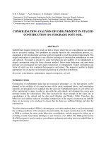
Figure III. 1 Pile boring machine HITACHI KH-100
2) Bentonite mixing machine
Due to the required volume of bentonite is 56.54m3 per day, select bentonite mixing
machine BE-15A with the following parameters:
Machine
Mixing tank volume (m3)
Productivity (m3/h)
Pressure (kN/m2)
BE-15A
1.5
15-18
1.5
3) Bentonite pumping machine
Pumping machine
Productivity (m3/h)
Duct diameter (mm)
Pumping pressure (kG/cm2)
4) Air compressor
Air compressor
Nguyen Duc Duy-565556-56XE
9
BSA 1002SV
20
150
76
HWO-5
Final year project
LAPAZ Tower
Capacity (kW)
Pressure (kG/cm2)
Air flow (l/min)
Selft-weight (kG)
5) Concrete mixer truck
Select DONGFENG12 concrete mixer truck (12m3 concrete mixer tank)
DONGFENG12 concrete mixer truck
Concrete capacity (m3)
Water tank capacity (m3)
Weight (T)
Output material speed (m3/min)
Average speed (km/h)
3.7
12
560
55
12
0.4
31
2
30
Effective concrete volume: 0.8 x 12 = 9.6m3
Time for a concrete truck to finish pouring concrete: 9.6 / 2 4.8(mins)
Use 3 concrete trucks with 5-10 minutes away from each other to pour concrete for one
bored pile.
6) Dump truck
Soil volume of one bored hole:
12
V � �30 23.56(m3 )
4
Time for boring 1 hole: 150 (minutes).
Select HUYNDAI HD270 dump truck having capacity 10m3.
Nguyen Duc Duy-565556-56XE
10
Final year project
LAPAZ Tower
Effective amount of soil: 0.8 x 10 = 8m3
Dumping location is 10km far from the construction site.
Average speed of dump truck: 30 km/h
Time for two-way-trip of a dump truck: t=tf + tt + td +tb
Where:
tf: Time for filling soil into dump bed (5 mins)
tt: Time for travelling 10k distance with average speed: 30km/h (20 mins)
td: Time for dumping and turning (5 mins)
tb: Time for getting back to construction site (20 mins)
t=tf + tt + td +tb=50 minutes
150
�8 24( m3 )
In 150 minutes, 1 dump truck can transport: 50
Select 1 dump truck for 1 bored pile.
Nguyen Duc Duy-565556-56XE
11
Final year project
LAPAZ Tower
7) Crawler Crane
Crane is used to lift up the reinforcement cages, casing pipe, tremie pipe. The weight of
casing pipe is about 0.5 Ton and the weight of the reinforcement cage is approximately
2.3T.
The follow parameters are used to select a suitable crawler crane for bored pile
construction:
Required capacity of crane: Q=2.3 T
Required height:
H = h 1 + h 2 + h 3 + h4
Where:
h1=0.5m: Safety distance
H2=11.7m: Length of reinforcement cage
H3=1.5m: Length of hanging equipment
H4=1.5: pulley length
H = h1 + h2 + h3 + h4 =15.2m
Required length of boom:
Lmin
H hc 15.2 1.5
14.18(m)
sin 750
sin 750
Required working radius:
R Lmin �cos 750 1.5 5.17( m)
Nguyen Duc Duy-565556-56XE
12
Final year project
LAPAZ Tower
Use HITACHI KH100 to lift up reinforcement cage, casing pipes, tremie pipes, etc with
the specification:
Working radius: 16m
Boom length: 19m
Load capacity: 2.75Ton
Figure III. 2 Specification of crawler crane HITACHI KH100
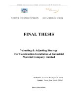
8) Excavator
Select Backhoe KOMATSU PC220LC-8 with the following parameters:
3
Bucket volume: q 1.0(m )
Weight:
25.5 T
Maximum digging reach at ground level: R 10.02( m)
Maximum dump height h 7.035(m)
Dumping radius rd 3.84( m)
Maximum digging depth H 6.92(m)
Nguyen Duc Duy-565556-56XE
13
Final year project
LAPAZ Tower
Slewing cycle: T 17(s )
Figure III. 3 Backhoe KOMATSU PC220LC-8
Productivity:
k
N q � d �ncycle �ktime
kt
Where:
q 1.0(m3 ) : Bucket volume
kd 0.95 : Factor of full-filling bucket
kt 1.15 : Swell factor
ktime 0.8
: Time factor
Nguyen Duc Duy-565556-56XE
14
Final year project
LAPAZ Tower
ncycle
3600
tcycle �kdw �kslewing
kdw 1.1
: Factor of soil dumping method
k slewing 1
tcycle 17( s )
: Slewing cycle
k
0.95 � 3600 �
N q � d �ncycle �k 1.4 �
��
�0.8 178.12(m3 / h)
�
kt
1.15 �
17 �1.1 �1 �
3
Productivity of backhoe per shift: N 178.12 �8 1424.98(m / shift)
II.3.5 Construction time
Construction time for one bored pile:
Move auger into boring position: 20 minutes.
Pile center positioning: 15 minutes.
Initial boring and casing pipe lowering: 10 minutes.
Boring to the elevation of -30.0 m from the natural ground level.
The productivity of auger is 15m3/h.
23.56
1.57(h) 94(mins)
15
Time for boring a D1000 pile:
Check the bored hole bottom elevation: 10 minutes.
Wait for deposition: 45 minutes.
Bored hole dredging (1st): 15 minutes.
Lower reinforcement cages: 60 minutes.
Lower tremie pipe: 60 minutes.
Bored hole flushing (2nd): 30 minutes.
Check bore hole bottom elevation: 15 minutes.
Pour concrete: 100 minutes
Nguyen Duc Duy-565556-56XE
15
Final year project
Remove casing pipe: 20 minutes.
Back filling: 20 minutes.
LAPAZ Tower
Total construction time of a bored pile:
T=20+15+10+94+10+45+15+60+60+30+15+100+20+20=514 minutes.
T=8hours 34 minutes.
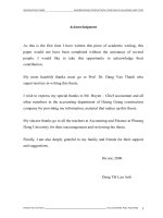
II.3.6 Machine movement
In accordance with Article 7.1 – TCVN 9395:2012 – “Bored Pile: Construction, Check
and Acceptance”, boring work of bored hole that is between two finished bored pile
should be executed at least 24 hours after the completion of concrete work.
2 working crews work simultaneously.
Nguyen Duc Duy-565556-56XE
16
Final year project
LAPAZ Tower
END
END
BEGINNING
BEGINNING
Figure III. 4 Machine movement in bored pile construction
Total movement of working crew 1: 248m.
Total movement of working crew 2: 245m.
II.3.7 Man power
Required man power for one crew:
Controlling auger: 1 worker.
Controlling crane: 1 worker.
Nguyen Duc Duy-565556-56XE
17
Final year project
LAPAZ Tower
Controlling backhoe: 1 worker.
Supporter for drilling work: 1 worker.
Labors for reinforcement work: 10 workers.
Labors for concrete work: 10 workers.
Labors for bentonite work: 2 workers.
Electrician: 1 worker.
Setting theodolite: 3 workers.
Two working crews work silmutaneously in bored pile construction. So total labor for
bored pile construction in one day is 60 labors.
CHAPTER III.
SHEET PILE CONSTRUCTION
III.1. CONSTRUCTION SOLUTION
According to the underground construction requirement and bored pile solution, the
construction method for underground work are shown as below:
Install sheet pile system around the perimeter of the construction area.
Excavate by manual 1.2m deep from the natural ground.
Nguyen Duc Duy-565556-56XE
18
Final year project
LAPAZ Tower
Install the anchorage system.
Excavate by excavator 5.9m from level the natural ground to the level -5.9m.
Excavate 0.1m from level -5.9m and fix the foundation pit manually.
Advantages of using sheet pile:
High strength.
Brace is not required or just a few.
Anchorage can be used to keep the stability.
Economic efficiency.
III.2. CALCULATION OF LARSSEN SHEET PILE
III.2.1 Geotechnical data
Table III. 1 Table of geotechnical data
No. Soil layer
Backfilling
1 soil
2 Clay mud
3 Clay sand
Brown
4 sandy clay
Grey sandy
5 clay
Grey clay
6 rock
Thic
knes
s
W
(%)
(g/
(g/
cm3) cm3)
4.0
17.52
2.66
5.8
1.6
51.23
28.49
1.70 2.64 18.69
1.86 2.68 9.24
0.063
0.091
5°54'
10°33'
6.2
18.11
2.06 2.68 8.70
0.152
13°56'
3.1
23.26
1.95 2.69 12.78
0.187
13°24'
18
110
21.23
1.97 2.71 12.08
0.244
19°20'
90
120
Ip
C
(kG/
cm2)
(degree)
E1-2
SPT (kG/
cm2)
7
1
9
11
30
60
110
At the time of this survey, the groundwater is at the elevation of - 7.0 (m) from natural
ground.
Nguyen Duc Duy-565556-56XE
19
Final year project
LAPAZ Tower
III.2.2 Larssen sheet pile calculation
1) Preliminary selection of Larssen sheet pile
Figure III. 5 Larssen sheet pile dimensions and Sectional Properties
Preliminarily select larssen sheet pile type II with the properties:
Sectional area: 61.18cm2.
Weight: 48kg/m.
Moment of inertia: 1.240cm4.
Section modulus: 152cm3.
2) Sheet pile calculation
Calculation requirement:
Calculate the sheet pile depth fixed on the soil to bear the positive pressure of soil.
The displacement of pile top is satisfied to the limit displacement.
Diagram of the sheet pile:
Nguyen Duc Duy-565556-56XE
20
Final year project
LAPAZ Tower
0.00
-4.00
-6.00
-9.80
-11.40
-17.60
Figure III. 6 Diagram of Larssen sheet pile.
Arccording to Rankine’s theory, calculate the positive and negative soil pressure. Then,
calculate the sheet pile depth fixed on the soil to be satisfied to the stable condition.
Kc, Kb are the positive and negative soil pressure ratio respectively. They are calculated as
below formulas:
K c tg 2 (45o )
K b tg 2 (45o )
2 and
2
Table III. 2 Positive and negative soil pressure ratio
g(T/m3)
Kc
Kb
Backfilling
4
soil
2.66
10.5
0.69
1.44
Clay mud
2.64
5.9
0.81
1.23
No.
Soil layer
1
2
Nguyen Duc Duy-565556-56XE
H(m)
5.8
21
Final year project
LAPAZ Tower
3
Sandy clay
and clay
1.6
sand
2.68
10.5
0.69
1.44
4
Brown
sandy clay
2.68
13.9
0.61
1.63
6.2
Positive soil pressure:
Pc ( z ) K c � �z 2 �c � K c q �K c
Negative soil pressure:
Pc ( z ) K b � �z 2 �c � K b q �K b
q = 1T/m2: Load account for the weight of the machine moving near the foundation pit.
a) Calculate the sheet pile depth fixed on the soil to bear the positive pressure of soil:
Determine the positvive soil pressure:
Soil layer 1:
z=0
Pc ( z 0) K c � �z q �K c 1�0.69 0.69(T / m 2 )
z=4
Pc ( z 4) K c � �z 2 �c � K c q �K c
0.69 �2.66 �4 2 �0.91� 0.69 1�0.69 6.5(T / m 2 )
+ Positive soil pressure on 1-m width:
1
1
Ec1 �H ��
Pc z 0 Pc z 4 �
�4 � 0.69 6.5 14.38(T / m)
�
�
2
2
+ The distance from the point that the concentrated positive force put on to the
natural ground.
H1
0.69 2 �6.5 4
� 2.54(m)
0.69 6.5
3
Soil layer 2:
z=4
Pc ( z 4) K c � �z 2 �c � K c q �K c
0.81�2.64 �4 2 �0.63 � 0.81 1�0.81 8.23(T / m 2 )
z=9.8
Nguyen Duc Duy-565556-56XE
22
Final year project
LAPAZ Tower
Pc ( z 9.8) K c � �z 2 �c � K c q �K c
0.81�2.64 �9.8 2 �0.63 � 0.81 1�0.81 20.63(T / m 2 )
+ Positive soil pressure on 1-m width:
1
1
Ec 2 �H ��
Pc z 4 Pc z 9.8 �
�5.8 � 8.23 20.63 83.69(T / m)
�
�
2
2
+ The distance from the point that the concentrated positive force put on to the
natural ground.
H2 4
8.23 2 �20.63 5.8
� 7.3(m)
8.23 20.63
3
Soil layer 3:
z=9.8
Pc ( z 9.8) K c � �z 2 �c � K c q �K c
0.69 �2.68 �9.8 2 �0.91� 0.69 1�0.69 17.3(T / m 2 )
z=11.4
Pc ( z 11.4) K c � �z 2 �c � K c q �K c
0.69 �2.68 �11.4 2 �0.91� 0.69 1�0.69 20.25(T / m 2 )
+ Positive soil pressure on 1-m width:
1
Ec 3 �1.6 ��
Pc z 9.8 Pc z 11.4 �
�
�
2
1
�1.6 � 17.3 20.25 30.04(T / m)
2
+ The distance from the point that the concentrated positive force put on to the
natural ground.
H 3 9.8
17.3 2 �20.25 1.6
� 10.62(m)
17.3 20.25
3
-Soil layer 4:
z=11.4
Pc ( z 11.4) K c � �z 2 �c � K c q �K c
0.61�2.68 �11.4 2 �1.52 � 0.61 1�0.61 16.9(T / m 2 )
z=11.7
Nguyen Duc Duy-565556-56XE
23
Final year project
LAPAZ Tower
Pc ( z 11.7) K c � �z 2 �c � K c q �K c
0.61�2.68 �11.7 2 �1.52 � 0.61 1�0.61 17.36(T / m 2 )
+ Positive soil pressure on 1-m width:
1
Ec 3 �0.3 ��
Pc z 11.4 Pc z 11.7 �
�
�
2
1
�0.3 � 16.9 17.36 5.14(T / m)
2
+ The distance from the point that the concentrated positive force put on to the
natural ground.
H 3 11.6( m)
Determine the negative soil pressure:
Soil layer 2:
z=0
Pc ( z 0) K c � �z 2 �c � K c q �K c 0(T / m 2 )
z=3.8
Pc ( z 3.8) K c � �z 2 �c � K c q �K c
0.81�2.64 �3.8 2 �0.63 � 0.81 1�0.81 10.07(T / m 2 )
+ Positive soil pressure on 1-m width:
1
1
Ec1 �H ��
Pc z 0 Pc z 3.8 �
�3.8 � 0 10.07 19.13(T / m)
�
�
2
2
+ The distance from the point that the concentrated positive force put on to the
natural ground.
H1 0
0 2 �19.13 3.8
� 2.53( m)
0 19.13
3
Soil layer 3:
z=3.8
Pc ( z 3.8) K c � �z 2 �c � K c q �K c
0.69 �2.68 �3.8 2 �0.91� 0.69 1�0.69 9.23(T / m2 )
z=5.4
Nguyen Duc Duy-565556-56XE
24
Final year project
LAPAZ Tower
Pc ( z 5.4) K c � �z 2 �c � K c q �K c
0.69 �2.68 �5.4 2 �0.91� 0.69 1�0.69 12.18(T / m 2 )
+ Positive soil pressure on 1-m width:
1
Ec 2 �1.6 ��
Pc z 3.8 Pc z 4 �
�
�
2
1
�1.6 � 9.23 12.18 17.13(T / m)
2
+ The distance from the point that the concentrated positive force put on to the
natural ground.
H 2 3.8
9.23 2 �12.18 1.6
� 4.64( m)
9.23 12.18
3
Soil layer 4:
z=5.4
Pc ( z 5.4) K c � �z 2 �c � K c q �K c
0.61�2.68 �5.4 2 �1.52 � 0.61 1�0.61 11.8(T / m2 )
z=5.7
Pc ( z 5.7) K c � �z 2 �c � K c q �K c
0.61�2.68 �5.7 2 �1.52 � 0.61 1�0.61 12.29(T / m2 )
+ Positive soil pressure on 1-m width:
1
Ec 2 �0.3 ��
Pc z 5.4 Pc z 5.7 �
�
�
2
1
�0.3 � 11.8 12.29 3.61(T / m)
2
+ The distance from the point that the concentrated positive force put on to the
natural ground.
H 2 5.4
Nguyen Duc Duy-565556-56XE
11.8 2 �12.29 0.3
� 5.55( m)
11.8 12.29
3
25