Final year project FULL
Bạn đang xem bản rút gọn của tài liệu. Xem và tải ngay bản đầy đủ của tài liệu tại đây (24 MB, 395 trang )
Final year project
LAPAZ Tower
Contents
ARCHITECTURE
Nguyen Duc Duy-565556-56XE
1
Final year project
LAPAZ Tower
PART I
ARCHITECTURE
(10%)
CHAPTER I. GENERAL INTRODUCTION
I.1 BUILDING LOCATION
Lapaz Tower locates at 38 Nguyen Chi Thanh, Thach Thang, Hai Chau district, Da Nang
city. It is very near from the building to the school, hospital, Danang administrative
center, Han river bridge…The building is expected to promote the economy and tourism
development of the city.
Nguyen Duc Duy-565556-56XE
2
Final year project
LAPAZ Tower
Figure I. 1 Location of LaPaz tower
The building is a complex of apartments, services.. and owned by Danang Housing
investment development joint stock company.
I.2 INVESTMENT NECESSARY
In the recent years, Vietnam’s economy has changed dramatically along with the rapid
growth of the other countries in Asia. The reconstruction and construction of
infrastructure is really needed. On the other hand, the replacement of low-rise buildings
by high-rise buildings is very necessary to resolve land issues as well as changing the
urban landscape to deserve with the stature of a large city.
Danang is one of the most important cities in Vietnam. With many beautiful landscapes,
Danang attracts million tourists each year. Nowadays, more and more people want to live
and work in Danang. Therefore, the construction of a high-rise building like La Paz Tower
is essential and appropriate to deal with the issue. After constructed, the building also will
be one of the landmarks or the city.
I.3 SCALE AND GENERAL FEATURES
The project consists of 17 upper stories and 2 basements. The total high of the building is
64.8m from ±0.000 level and the basement is at -4.400m deep.
The functions:
− Basement 1 and 2 is used as a parking area for residents and customers. The
technical rooms like power room, pumping room…is put in the basement 2.
Nguyen Duc Duy-565556-56XE
3
Final year project
−
−
−
−
LAPAZ Tower
The first floor: mini supermarket, mini shop and office rooms for hire.
The second floor: office rooms for hire.
Floor 3- 17: residential apartments.
The eighteenth floor: lift technical room and water tank.
The technical parameters:
−
−
−
−
−
Each basement area: 596 m2.
The first floor area: 594 m2.
The second floor area: 616 m2.
The third to seventeenth floor area: 625 m2.
The eighteenth floor area: 80 m2.
CHAPTER II. ARCHITECTURE SOLUTION
II.1 DESIGN OF MASTER PLAN
There are 2 basements that is used for parking and putting some technical system like
water tank, power room…The area of each basement is 596m2. There is a staircase from
the basement 2 for people moving conveniently.
The first and second floor are used for market, shop, office for release. 2 elevators and 1
staircase are installed to move vertically.
Apartments are located from the third to the seventeenth floor. Each apartment is designed
independently and connected together by lobbies.
There are 7 apartment types:
− S1 and S4 apartment: 2 bedrooms – S=92.6m2.
− S2 and S3 apartment: 2 bedrooms – S=74m2.
− S5 apartment: 2 bedrooms – S=96.5m2.
Nguyen Duc Duy-565556-56XE
4
Final year project
LAPAZ Tower
− S6 apartment: 1 bedroom – S=44.8m2.
− S7 apartment: 2 bedrooms – S=78.1m2.
In each floor, the lobbies are designed to move conveniently. The elevators are the center
of the floor. There is a emergency staircase that is used for dangerous situation.
-4.400
-4.400
TP
TP* c h
l bt
TP*
TP
s11
1000 kg
800 kg
d 13*
-4.400
-4.400
-4.400
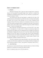
Figure I. 2 Plan layout of the second basement
Nguyen Duc Duy-565556-56XE
5
Final year project
LAPAZ Tower
-1.200
-1.200
TP
TP* c h
l bt
TP*
TP
s11
1000 kg
800 kg
d 13*
-1.200
-1.200
-1.200
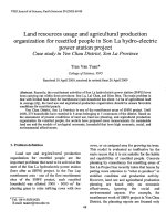
Figure I. 3 Plan layout of the first basement
Nguyen Duc Duy-565556-56XE
6
Final year project
LAPAZ Tower
s7d c
s10
s7d c
WC FOR MEN
THU
RÁC
d 14
TP
s7
d 11a
+2.000
dw1
s8d c
TP
s7d c
+2.000
WC FOR WOMEN
EXIT
s7d c
d 13a
dw1
s6d c
d 11
TP* c h
s11
1000 kg
MINI-MART
140 M2
OFFICE FOR RELEASE
s5d c
s5d c
800 kg
REC EPTION DESK
+2.000
329 1342 329
d 13*
S1
200
S2
2965
200
200
300
s15a
MINI SHOP
+2.000
1342
S1
1342
MAIN ENTRANCE
S1
s1
s1
dc 1
WAY TO PARKING AREA
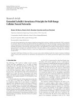
Figure I. 4 Plan layout of the first floor
Nguyen Duc Duy-565556-56XE
7
+0.000
Final year project
LAPAZ Tower
s10
s13d c
s10
s13dc
WC
FOR MEN
s10
s13dc
s17
s13dc
TP
WC
FOR WOMEN
s14dc
s21d c
s22
d 13a
dw1
dw1
d 11
TP
TP*
d 16
s21d c
d 11
ch
s11
1000 kg
s15dc
800 kg
s15d c
1342
OFFICE FOR RELEASE
329 1342 329
d 13
OFFICE FOR RELEASE
a r ea f o r c o mmunity ac tivities
BAR
s18
s20
s19
s18
s19
Figure I. 5 Plan layout of the second floor
Nguyen Duc Duy-565556-56XE
8
Final year project
LAPAZ Tower
A
C
s24a
s24a
s26
l n2
k
s25
WC 8
BEDROOM 1
ph¬i
LIVI NG ROOM
BEDROOM 1
dw
d 21
tk12
s26
l n2
ph¬i
KITCHEN
d 21
k
DINI NG-ROOM
dw
r¸ c
d 20
s23
BEDROOM 1
LIVI NG ROOM
s24a
WC 7
KITCHEN
s24
s24a
d 19
d 19
d 13a
d 18
d 19
ph¬i
l n2
LIVING ROOM
d 20
d 20
TP
TP* c h
TP
dw
KITCHEN
dw
d 21
d 19
d 19
s11
WC 5a
s23
WC 5
1000 kg
900
BEDROOM 2
d 19
BEDROOM 2
900
BEDROOM 2
BAR
d 21
d 19
dw
s25*
d 13
WC 4
LIVI NG ROOM
WC 4
dw
DINING-ROOM
TP*
900
900
d 20
kt
s26
s26
k
s26
BEDROOM 1
d 19
d 20
s25
d 20
d 19
WC 2
dw
dw
BEDROOM 1
TP
d 19
WC 2
WC 3
d 21
ch
900
d 19
KITCHEN
s26
WC 3
dw
KI TCHEN
dw
d 19
900
BEDROOM 1
WC1
WC1
d s1
d s2
d s1
LIVING ROOM
d 21
k
BEDROOM 1
dw
dw
d 19
BAR
LIVING ROOM
dw
TP
TP
d 20
s25
BALCONY
l n2
800 kg
KI TCHEN
900
B
s25*
BEDROOM 2
WC 6
ph¬i
l n2
s23
LIVI NG ROOM
s23*
BALCONY
d 21
BEDROOM 2
BEDROOM 2
BALCONY
s24*
s24*
l n1
BALCONY
s23*
A
C
Figure I. 6 Plan layout of typical floor (from the third to the seventeenth floor)
Nguyen Duc Duy-565556-56XE
9
B
Final year project
LAPAZ Tower
i =1 %
900
600
500
2000
PLASTIC PIPE O 100 FOR DRAINAG E
200
2300
2150
PLASTIC PIPE o 80 FOR DRAINAGE
s26
600 1250
s26
s11
s26
700
400
6000
TEC HNIC AL ROOM
d 13
d 23
200500 1350 500200
200TP
c h200
i =1 %
2050
2100
2100
s26
600
600
100
2300
d23
600
1250
d 24
5050
i =1 %
850
i =1 %
1450
100
2150
450
1300
3200
8600
i =1 %
850
600
i =1 %
1600
1200
200
i =1 %
i =1 %
i =1 %
300
200 1700
i =1 %
700
200
i =1
i =1
%
%
PLASTIC PIPE O 100 FOR DRAINAG E
PLASTIC PIPE O 100 FOR DRAINAG E
Figure I. 7 Plan layout of top and technical floor
II.2 DESIGN OF FACADE
The building has a modern shape and is designed as a landmark of Danang city.
Nguyen Duc Duy-565556-56XE
10
800
550
2000
650
900
900
2100
4500
4*
Nguyen Duc Duy-565556-56XE
2100
1500
1500
900
1500
500
2350
400 1300
3400
3400
4800
1200 500
8
6
9
9
9
8
8
100
1350
2800
22300
11
3000
8
1*
400
2200
1900
2500
400 1300
1700
1700
1200 500
400 1300
1700
1700
1200 500
400 1300
1700
1700
1200 500
400 1300
1700
1700
1200 500
48400
1700
3400
8
8
1700
10*
8
1700
1700
3400
9
8
4
1700
1200 500
3400
11
8
8
2700
400 1300
3400
3400
3400
3400
1200
900
400 1300 500
1700
1700
1200 500
400 1300
1700
1700
1200 500
400 1300
1700
1700
1200 500
400 1300
1700
1700
1200 500
400 1300
1700
1700
1200 500
3400
1700
1400
3400
900
1200 500
1100
14400
3400
1700
1300
1200
1200
8
9
6
9
8
4
4
3
3
3
1400
1300
200
1000
200
1000
1200
8
400 1300
1700
3400
8
2100
1500
3400
8
900
2100
4500
4200
2000
Final year project
LAPAZ Tower
The building is exposed the sunshine extremely from all 4 directions. The doors and
windows are made of color glass, that make the building more beautifully.
12
8
650
4*
1500
1500
900
1050
500
2850
8800
Nguyen Duc Duy-565556-56XE
900
2850
3000
8a
1800
7200
16000
12
1200 500
500
1700
9
1200 500
500
3*
500
2801
500
1200 500
1200
150
1*
500
1000
3200
1000
1550
2850
8800
12000
Figure I. 9 Elevation layout 5-1
900
2850
500
1200 500
1200
500
1200 500
1200
1700
4
4
4
400
3
1050
4*
3400
1700
6
3400
1700
1700
1200
500
1700
3400
64800
1200 500
8
3400
1700
1700
8
3400
1700
1700
3400
8
3400
1700
1200
3400
8a
3400
1700
1200
3400
8
1500
500
1700
3400
3400
1700
11
4500
2100
1500
3400
8
900
2100
3400
500
1200 500
1200
3400
3400
1700
1700
500
1200 500
1200
3400
3400
1700
1700
500
1200 500
1200
3400
3400
1700
1700
500
1200 500
1200
3400
3400
1700
1700
500
1200 500
1200
3400
3400
1700
1700
500
1200 500
1200
3400
3400
1700
1700
1200
1200
8a
4500
2100
2100
4500
900
500
3400
1700
3400
1300
9
900
1000
1000
900
4500
8
2000
800
550
2000
1200
1200
4200
2000
Final year project
LAPAZ Tower
Figure I. 8 Elevation layout F-
5
12
8
2000
2
5
3
1500
8
2000
2000
900
Nguyen Duc Duy-565556-56XE
4000
5800
1100
8
1700
600 1100
1800
600 1100
1800
900
2200
600 1100
1800
4
1
3000
8000
4000
13
2800
1200
600 1100
1800
3
400
2070
1800
8
4
5200
930 800
22300
Figure I. 10 Elevation layout A-F
8
8
4*
500
1000
3300
1800
100
600 1100
9
4
4
3*
2
4*
3400
1700
400 1200
3400
8
3400
1700
400 1200
3400
9
3400
1700
400 1200
3400
8
3400
1700
400 1200
3400
9
3400
1700
400 1200
3400
400 1200
3400
3400
1700
8
3400
1800
600 1100
400 1200
3400
9
1500
1800
8
10*
4500
2100
1500
8
900
4500
2100
8
4500
2100
900
1800
600 1100
6
900
1000
8
1000
4500
2100
11
2000
900
3400
1700
1800
600 1100
400 1200
3400
3400
1700
1800
600 1100
400 1200
3400
3400
1700
1800
600 1100
400 1200
3400
3400
1700
1800
600 1100
400 1200
3400
3400
1700
500
500
600
400 1200
3400
3400
3400
1700
1700
900
1200 500
1200
3400
3400
1700
1300
500
700
200
1200 1000
4200
2000
Final year project
LAPAZ Tower
05
12
Final year project
LAPAZ Tower
II.3 DECORATED MATERIAL SOLUTION
High quality inland materials are used for the building like granite and ceramic tiles
VIGRACERA, sanitary wares INAX. Using industrial timber for doors, glass material for
windows.
CHAPTER III. TECHNICAL AND INFASTRUCTURE SOLUTION
III.1 LIGHTING SYSTEM
Natural light is fully utilized. The window systems in all facades are glazed. In addition,
artificial light is also arranged so that it can cover all points that need lighting.
Nguyen Duc Duy-565556-56XE
14
Final year project
LAPAZ Tower
III.2 VENTILATION SYSTEM
Through the window system, natural ventilation is fully utilized. Besides, there is air
conditioning system. The pipe system is laid in the vertical and horizontal technical box,
distributes evenly to the places of consumption.
III.3 POWER SYSTEM
The medium voltage line 15KV goes to the substation through the underground pipe
system. There is also backup power, two generators, located in the basement of the
building. When main power is lost, the generators will serve the following cases:
- The fire protection system
- Lighting system and protection
- Working offices
- Vertical transport system
- Computer system and other critical services.
III.4 WATER SUPPLY AND DRAINAGE SYSTEM
III.4.1 Water supply
Water from the water supply system of the city goes into the underground tank situated in
the basement of the building. Water is pumped to the roof tank automatically, and then
follows the technical pipeline to the consumptions.
III.4.2 Drainage
Rainwater on the roof, logia, balcony, and domestic wastewater is collected to se-no
leading to the treatment tank. Handled water will be given to the drainage system of the
city.
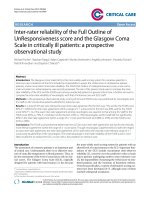
III.5 FIRE PROTECTION SYSTEM
III.5.1 Warning system.
Fire alarms are installed in all rooms of building. This net is equipped sprinklers for fire
fight and information network to give warns when detecting any problem.
Nguyen Duc Duy-565556-56XE
15
Final year project
LAPAZ Tower
Figure I. 11 Sprinkler
III.5.2 Fire fight solution.
Along lobby, we put CO2 bottles for firefight in case of happening fire.
On each floor, the building has emergency stair, so it is necessary to make sure that people
can escape in the dangerous situation.
A fire hydrant is designed outside the building to sever fire trucks.
III.5.3 Fire resistance.
The major disadvantage of the steel structure is that the bearing capacity is affected by
temperature. When the temperature reaches 550o C, the steel structure begin instability
and this leads to vandalism. Mandatory requirements for steel structures is to be covered
against fire, "dressed" steel structure 1 "armor layer " to against high temperatures in one
certain time, a chance to extinguish the fire escape from the fire safely. Fire protection
requirements for the time resisting fire is 120 minutes, so the structural steel columns and
beams need to be protected in the corresponding period.
In terms of this project, the solution was chosen is using gypsum to cover steel
structure.
We will set up a supporting frame to carry gypsum and cover the steel columns and beams
Nguyen Duc Duy-565556-56XE
16
Final year project
LAPAZ Tower
Figure I. 12 Gypsum covers steel columns.
Figure I. 13 Gypsum covers steel beams.
Nguyen Duc Duy-565556-56XE
17
Final year project
LAPAZ Tower
This solution is cheapest; compare to 2 other solutions, non-toxic, guarantee fire resistant
standards (resist fire in 3 hours). And this method can also satisfy many requirements of
architecture.
III.6. WASTE DISPOSAL SYSTEM
Waste of each floor will be collected and taken downstairs technical storey, basement by
waste collection tube. The waste is processed every day.
Nguyen Duc Duy-565556-56XE
18
Final year project
LAPAZ Tower
PART II
STRUCTURE
(45%)
Nguyen Duc Duy-565556-56XE
19
Final year project
LAPAZ Tower
CHAPTER I. STRUCTURAL SOLUTION
I.1 SUPERSTRUCTURE SOLUTION
I.1.1 Basic structural system
1) Frame Structure
Frame structures are the structures having the combination of beam, column and slab the
large moments developing due to the applied loading.
2) Rigid diaphragm.
Figure II. 1 Concrete diaphragm.
Nguyen Duc Duy-565556-56XE
20
Final year project
LAPAZ Tower
In structural engineering, a diaphragm is a structural element that transmits lateral load to
the vertical resisting elements of a structure (such as shear walls or frames). Diaphragms
are typically horizontal, but can be sloped such as in a gable roof on a wood structure or
concrete ramp in a parking garage. The diaphragm forces tend to be transferred to the
vertical resisting elements primarily through in-plane shear stress.
The most common lateral loads to be resisted are those resulting from wind and
earthquake actions, but other lateral loads such as lateral earth pressure or hydrostatic
pressure can also be resisted by diaphragm action.
The diaphragm of a structure often does double duty as the floor system or roof system in
a building, or the deck of a bridge, which simultaneously supports gravity loads.
3) Braced Structural Frames.
Figure II. 2 Braced structural frame
In this frame system, bracing are usually used to connect beams and columns to increase
their resistance against the lateral forces and side-ways forces due to applied load.
Bracing is usually done by placing the diagonal members between the beams and
columns.
This frame system provides more efficient resistance against the earthquake and wind
forces. This frame system is more effective than rigid frame system.
Nguyen Duc Duy-565556-56XE
21
Final year project
LAPAZ Tower
I.1.2 Combination structural system
1) Braced frame
A Braced Frame is a structural system which is designed primarily to resist wind and
earthquake forces. Members in a braced frame are design to work in tension and
compression, similar to a truss. Braced frame are almost always composed of steel
members.
2) Core – tube
Tube structure system works more effective if arranging core wall at the center. Core wall
is subjected to both vertical and horizontal load. Core wall can be combined of shear
walls of smaller tube.
I.2 MATERIAL SOLUTION FOR SUPERSTRUCTURE
There are many types of frame structure can apply for this project:
− Concrete structure (including concrete columns, concrete beams) with concrete
slab.
− Steel structure (including steel columns, steel beams) with composite slab.
− Composite structure (including composite columns, composite beams) with
composite slab.
Each structure has its own advantages:
− Concrete structure:
+ Reinforced concrete has a high compressive strength compared to other building
materials.
+ Due to the provided reinforcement, reinforced concrete can also withstand a good
amount tensile stress.
+ Fire and weather resistance of reinforced concrete is fair.
+ The reinforced concrete building system is more durable than any other building
system. Reinforced concrete, as a fluid material in the beginning, can be
economically molded into a nearly limitless range of shapes.
+ The maintenance cost of reinforced concrete is very low.
+ In structure like footings, dams, piers etc. reinforced concrete is the most
economical construction material.
+ It acts like a rigid member with minimum deflection.
+ As reinforced concrete can be molded to any shape required, it is widely used in
precast structural components. It yields rigid members with minimum apparent
deflection.
Nguyen Duc Duy-565556-56XE
22
Final year project
LAPAZ Tower
+ Compared to the use of steel in structure, reinforced concrete requires less skilled
labor for the erection of structure.
− Steel structure:
+ Health and safety for employees working in construction site.
+ Sustainability while using process (because of the balance between the three
factors: exceptional environmental, social and economic benefits).
+ High quality (steel offers consistently high quality standards, precision products
and guaranteed strength and durability in the most challenging environments).
+ High speed construction (especially compare to concrete structures).
+ Economic (Independent studies consistently show that steel is the most costeffective framing solution for multi-storey construction).
− Composite structure:
Advantageous properties of both steel and concrete are effectively utilized in composite
structure. High load capacity with small cross-section and economic material use (this
leads is more usable space).Composite section have higher stiffness than corresponding
steel section (in a steel structure) thus deflection is lesser. Encased steel sections have
improved fire resistance and corrosion. Reduction in overall weight of structure thereby
reduction in foundation cost. However, addition cost for shear connectors and theirs
installation (with composite beam). The lightly load short beams, this extra cost may
exceed the cost-reduction on all accounts.
I.3 BEARING COMPONENTS SOLUTIONS
I.3.1 Horizontal load bearing component
For the building with the height greater than 40m, there are some suitable structural
system to bear the horizontal load:
− Frame structure.
− Bracing-core combination structure.
− Core-frame combination structure.
Nguyen Duc Duy-565556-56XE
23
Final year project
LAPAZ Tower
Figure II. 3 Top displacement of some structural system
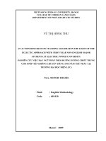
I.3.2 Bearing vertical loading.
1) Columns.
Columns are the main components carrying loading of building before transferring it to
the foundation. In most of case, columns are compressive; however, sometimes, column
will be bent along 1 axis or 2 axes. To choose the cross section of columns for a structure,
we need to consider many factors: bearing capacity, manufacture condition, connectors,
etc. to enhance the effectiveness and get the best case.
The following figure will show some popular column cross- sections:
Nguyen Duc Duy-565556-56XE
24
Final year project
LAPAZ Tower
Figure II. 4 Column cross-sections.
In terms of this building, cross- section b is chosen because it is totally suitable for
manufacture conditions and the bearing capacity condition.
2) Slab.
Slab is the main component which bears the dead loads and live loads while using
process. Thereby, slab has big influence on the behavior of structure. Choosing the
solution for the slab is a very important task. In order to choose suitable solution, we need
to analyze pros and cons of many different solutions. If the thickness of slab is not
enough, this will lead to cracks while using and make the deflection higher than demands.
There are many options for designing the slab in this project: concrete slab, flat composite
slab, composite slab, etc.
Regard to concrete slab, this is the most common slab in construction. Concrete flooring
is a common type of flooring adopted by many building owners. Concrete flooring can be
used in residential, commercial, institutional & public buildings of all types. With a long
durability, meets demands of bearing capacity and deflection, calculate and construct
easily, concrete slab is a good solution.
Nguyen Duc Duy-565556-56XE
25