ROAD CONSTRUCTION PROJECT THROUGH TWO POINTS A B
Bạn đang xem bản rút gọn của tài liệu. Xem và tải ngay bản đầy đủ của tài liệu tại đây (666.15 KB, 98 trang )
CONTENTS:
LIST OF FIGURES AND TABLES:
FIGURES:
TABLES:
PREFACE
In the career of building and protecting country, communication and transport are
essential contributing important roles. Along with country's continuous development in
the past years, field of capital construction generally and civil engineering construction
in particular have invested by government and party and having deservedly proud
achievements. In the next years, in order to implement the career of modernization and
industrialization, communication and transport must precede a step, serve purposes of
socio-economic development.
In the recent years, the government is investing much in transportation and
communication; advanced constructing technologies are applied in Vietnam. To apply
in fact, civil engineers’ level must be better and better.
Aware of that, and want to contribute to the overall development of the country, I have
chosen myself and go deep specialist research Highway and Traffic Department of
Bridge and Road Faculty, National University of Civil Engineering.
Graduation project is the result of the accumulation of knowledge during learning and
research in the university. After learning and gathering knowledge in National
University of Civil Engineering, now i am designing a graduation thesis:
“ROAD CONSTRUCTION PROJECT THROUGH TWO POINTS A-B"
This is important works with a large volume of work includes all steps from the
preliminary design, engineering design, and construction design. Therefore, despite
my best efforts, but certainly I can not avoid mistakes. I look forward to the comments
of the teacher let me get more rewarding things.
I sincerely thank the teachers in the Department of Highways and Traffic Engineering,
the teachers of the National University of Civil Engineering has taught me during
study time and research at school. Especially Do Duy Dinh, who has dedicated guide
and help me fulfill this graduation project.
Thank to you sincerely!
Hanoi, Dec-2017
Student: Ngo Trung Phuong
NATIONAL UNIVERSITY OF CIVIL ENGINEERING
HIGHWAY AND TRAFFIC ENGINEERING DEPARTMENT
GRADUATION PROJECT - REPORT
LECTURER: ASSOC. PROF. DR. VU HOAI NAM
PART 1:
PROJECT DEVELOPMENT AND PRELIMILARY
DESIGN FOR ROAD CONSTRUCTION CONNECTING
2 POINTS A-B
Project
:
Project development for road construction connecting A-B
Investor
:
Pepeple's Commite of Vinh Phuc
Adress
:
No.38-40 Nguyen Trai St, Dong Da precinct, Vinh Yen city, Vinh
Phuc province
NGÔ TRUNG PHƯƠNG – 58CDE - 3293458
5
NATIONAL UNIVERSITY OF CIVIL ENGINEERING
HIGHWAY AND TRAFFIC ENGINEERING DEPARTMENT
GRADUATION PROJECT - REPORT
LECTURER: ASSOC. PROF. DR. VU HOAI NAM
CHAPTER 1:
GENERRAL INTRODUCTION
1.1. Overview:
Designated route project through two points A-B is an important project to from
Phuc Yen commune to Vinh Yen city as well as a route of provincial sustem planned of
Vinh Phuc. This route is a connection between two important economic zones, politic
and traditinal zone of the province. The project will be served a good transportation
system for transporting the good and easy for driving between Phuc Yen commune and
Vinh Yen city to facilitate economic, tourist of developing area. To facilitation for the
province, ministry of transportation try hard to find out animportant route A-B and call
upon the investors to study more detail about this project.
1.2. The object scope of the project research and implement projects:
- The route through two point A-B of provincial highway connected from Phuc Yen
commune to Vinh Yen city.
- Route length is about 5000m.
- Points A belongs to Phuc Yen commune – Vinh Phuc province with the elevation of
390m compared to the sea level.
- Points B belongs to Vinh Yen city – Vinh Phuc province with the elevation of 350m
compared to the sea level.
1.3. Relatet resources documents:
- The overall planning of economic development and social of Phuc Yen commune in
2015-2025.
- Specialized planning, land use planing, social work place system.
- The results of investigation, surveying and data, document on hydrometeorology,
oceanographic, geological, scio-econ status and other metrics related documents.
1.4. Natural features of the zone along the route and regional trafiic conditions:
∗ General information:
− Geographic location: Vinh Phuc is bounded by Thai Nguyen and Tuyen Quang to
the north, by the Phu Tho to the west, Ha Tay to the south and Ha Noi to the east.
− Area: 1.2318km2.
− Topographic features: Vinh Phuc is situated in the top of “Pink river” Delta and is
the meeting point between plain and mountain. Therefore, it is divided into 3
regions: plain in the south of the province, midland in the north and mountains in
Tam Dao district.
− Administractive units: the province is divided into a city (Phuc Yen) and 6
districts: Binh Xuyen, Lap Thach, Tam Duong, Tam Dao, Vinh Tuong, Yen Lac.
− Population: 1,008,300 people.
∗ Resouroes:
NGÔ TRUNG PHƯƠNG – 58CDE - 3293458
6
NATIONAL UNIVERSITY OF CIVIL ENGINEERING
HIGHWAY AND TRAFFIC ENGINEERING DEPARTMENT
GRADUATION PROJECT - REPORT
LECTURER: ASSOC. PROF. DR. VU HOAI NAM
− Natural resources: Vinh Phuc has a large forest area especially Tam Dao forest
with various and diversified resources: 260 types of timbers and plants including
precious wood such as Fokienra and precious mineral found in the province such
as tin, gold and others with large reserves used for construction material
production such as sand, stone, limestone, construction rock, granite stone (50
million m2), they are mainly found in torism spot and Tam Dao National park.
− Tourism resources: it is lucky gor Vinh Phuc to arn beautiful sceneries as Tam
Dao, Tay Thien, Thien Vien, Dai Lai, Dam Vac,… Tam Dao tourism spot is
considered one of the best place of interest in the Northern Viet Nam. And Thac
Bac Xa Huong cake, Lang Ha dam and primeval forests,… will be unforgotten
memory of any visitors.
− Human resources: the province’s labour force is abundant, accounting for 61.6%
of the total population. There are many universities, professional, vocation
schools at central level located near the province. The province has 20,000 pupils
and 10,000 school graduates each year. Therefore, the local labour force can meet
the demand for economic development in term of quantity and quality.
∗ Infrastructure:
− Transportation system: the system is convenient with roadway and railway.
Beside, the province is situated near Noi Bai International Airport. There are 4
national highways No.2, 2B, 2C, 23 running through the province. There are
several large rivers (Ca Lo, Pho Day and Pink river) running through the
province, which earates favourable conditions for constructing Chu Phan, Vinh
Thinh and Nhu Thuy Ports for transportation of materials, goods, equipment,
facilities from Hai Phong, Quang Ninh seaports to the province.
− Water and power supply system: the system is quite complete meeting the
demand of households and production. There are two 110KV transformer
stations, one in Vinh Yen with the capacity of 65,000KVA, the other in Phuc Yen
with the capacity of 40,000KVA.
− Industrial zones: Vinh Phuc has 9 industrial zones and clusters: Kim Hoa I2 (117
hectares), Binh Xuyen I2 (271 hectares), Binh Xuyen II I2 (485 hectares), Khai
Quang (262 hectares), Ba Thien I2 (327 hectares), Ba Thien II I2 (308 hectares),
Chan Hung (150 hectares). Vinh Phuc continious to get govermental permission
to open 14 new industrial zones with the total area of 5576 hectares.
1.5. Summary the economic conditions:
* Economic situations:
- Grow rate: Vinh Phuc has enjoyed high growth rate (even much highter than that of
the country) thanks to its priorities given to investiment, exploitation of all potential
and of all resources for average growth rate was 1736%, espeeially in 2006 the rate
reached 19.8% ranking at the 7th nationwide.
Year
GDP (%)
2006
19.8
2007
22.9
2008
17.77
2009
8.5
2010
19.11
* Economic structure: shifted in the positive way that is to increase the proportion of
industry and services while decrease that of agriculture, forestry and auaculture:
NGÔ TRUNG PHƯƠNG – 58CDE - 3293458
7
NATIONAL UNIVERSITY OF CIVIL ENGINEERING
HIGHWAY AND TRAFFIC ENGINEERING DEPARTMENT
Year
Agriculture
- Forestry
- Aquaculture(%)
Industry – contruction (%)
Services (%)
NGÔ TRUNG PHƯƠNG – 58CDE - 3293458
GRADUATION PROJECT - REPORT
LECTURER: ASSOC. PROF. DR. VU HOAI NAM
2006
2007
2008
2009
2010
16.9
14.3
14.7
12.7
14.0
57.1
26.0
61.1
24.6
60.0
25.2
-
56.0
30.0
8
NATIONAL UNIVERSITY OF CIVIL ENGINEERING
HIGHWAY AND TRAFFIC ENGINEERING DEPARTMENT
GRADUATION PROJECT - REPORT
LECTURER: ASSOC. PROF. DR. VU HOAI NAM
CHAPTER 2:
CRITERIA FOR DESIGN
2.1. General:
According to assessment experts, the section will be the key to economic development
of the region. According to the survey data on the actual demand for traffic shows that
the tank is relatively stable. Therefore, in the calculation of grade scale and technical
standards of road should do well, this is the first problem to solve the traffic problem.
2.2. Design bases:
- Function of road: This is part of the Provincial Highway, connecting two socioeconomic, political center of Vinh Phuc Province.
- Terrian: Mountainous terrian.
- Traffic data:
According to traffic forecast and traffic data, traffic volume on the route through
two points A - B in the 15th year is 3200 vehicles per day, inculde:
Car (Volga)
: 25%
Light truck (Gaz-51)
: 25% (Front axle 18kN, rear axle 56kN, double wheels)
Medium truck(Zil150) : 25%(Front axle 25.8kN, rear axle 69.6kN, double wheels)
Heavy truck (Maz200) : 15% (Front axle 48.2kN, rear axle 100kN, double wheels)
Heavy truck (Maz504) : 10% (Front axle 45.4kN, rear axle 95kN, double wheels)
Traffic growth rate
: q = 6%
Formular for calculating traffic volume each year:
Nt = N0.(1+q)t
- 1st year traffic volume (N0)
N15 = N0 (1+q)15 ⇔
N0 =
3200
(1 + 0.06)15
= 1335 veh/day
2.3. Determine highway classification and technical:
2.3.1. Classification determination:
Table 1.2.3.1.1.a.i.1. Passenger car unit
Type
Propotion
Convert coefficient
Car
25 %
1
Light truck
25 %
2.0
Medium truck
25 %
2.0
NGÔ TRUNG PHƯƠNG – 58CDE - 3293458
9
NATIONAL UNIVERSITY OF CIVIL ENGINEERING
HIGHWAY AND TRAFFIC ENGINEERING DEPARTMENT
GRADUATION PROJECT - REPORT
LECTURER: ASSOC. PROF. DR. VU HOAI NAM
Type
Propotion
Convert coefficient
Heavy truck (1 rear axle)
15 %
2.5
Heavy truck (2 rear axles)
10 %
4.0
15th year convert volume:
Npcu/day = (25%×1 + 25%×2.0 + 25%×2.0 + 15%×2.5 + 10%×4.0) ×3200 = 6480
(pcu/day)
Follow table 3 and table 4 [1]
Propose:
+ Grade
: Grade III – mountainous terrain
+ Design speed
: Vtk= 60Km/h
2.3.2. Determine cross-section elements:
2.3.2.1. Carriage way:
a) Number of lane:
On Grade III road, the minimum number of lane is 2(lanes)
Calculation base on volume-to-capacity ratio Z :
N cdg
Z=
n lx × N lth
Where:
Z - volume-to-capacity ratio. For mountainous road, Vtk = 60km/h
=> choose Z = 0.77
Ncdg - rush-hour design traffic capacity converted to PCU
÷
For general: Ncdg = (0.10 0.12)×Ntbnđ , hence:
Ncdg = 0.11×6480 ≈ 713 (xcqđ/h)
nlx - is the number of lanes required, nlx= 2 (lane)
Nlth - actual capacity of through traffic flow, which is determined, if there is no
study and calculation, as follows: When there is no separator between the vehicles in
the opposite directions and motor vehicles use the same lane with non-motorized ones,
choose Nth = 1000 PCU/h/lane.
Therefore:
Z=
713
2 × 1000
= 0.356 < 0.77
Propose: choose number of lane: nlx = 2 (lanes).
NGÔ TRUNG PHƯƠNG – 58CDE - 3293458
10
NATIONAL UNIVERSITY OF CIVIL ENGINEERING
HIGHWAY AND TRAFFIC ENGINEERING DEPARTMENT
GRADUATION PROJECT - REPORT
LECTURER: ASSOC. PROF. DR. VU HOAI NAM
b) Width of traffic lane:
Calculation for 3 diagrams with 2 type of vehicle:
+ Car with small size and high speed, V= 80Km/h
+ Truck with big size and slow speed, V= 60Km/h
Width of traffic lane is calculated as below:
B1làn=
Where:
b+c
+x+y
2
(m)
b - width of tank
c - distance between 2 wheels
x - distance from edge of tank to the next-to lane
y - distance from wheel line to the edge of carriage way
According to Zamakhaev: x = y = 0.5 + 0.005×V
As these diagrams:
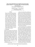
Diagram 1:
s ¬ ®å t Ýn h bÒ r é n g ph Çn xe c h ¹ y ( s ¬ ®å I )
b2
c2
x2
y2
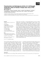
Figure 1.2.3.2.1.b.i.1.1. Two trucks go in opposite directions on two lanes and meet
each other
Two contrariwise truck:
b = 2.65m , c = 1.95m , V = 60 Km/h
Thus:
x = y = 0.5 + 0.005×60 = 0.8 m
Normaly, we have:
B1= B2=
(1.95 + 2.65)
+ 0.8 + 0.8
2
= 3.90 m
Width of carriageway: B= B1+B2 = 3.90 + 3.90 = 7.80 m.
Diagram 2:
NGÔ TRUNG PHƯƠNG – 58CDE - 3293458
11
NATIONAL UNIVERSITY OF CIVIL ENGINEERING
HIGHWAY AND TRAFFIC ENGINEERING DEPARTMENT
GRADUATION PROJECT - REPORT
LECTURER: ASSOC. PROF. DR. VU HOAI NAM
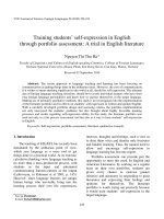
s ¬ ®å t Ýn h bÒ r é n g phÇn x e c h ¹ y ( s ¬ ®å II )
Figure 1.2.3.2.1.b.i.1.2. Two cars go in the opposite direction and meet each other
Assume: b = 1.54m , c = 1.22m , V= 80Km/h
Thus:
x = y = 0.5+ 0.005V = 0.5+0.005.80 = 0.9m
Normaly, we have:
B1= B2 =
1.54 + 1.22
+ 0.9 + 0.9
2
= 3.18 m
Width of carriageway: B= B1+B2 = 3.18 + 3.18= 6.36m.
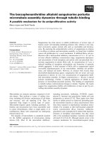
Diagram 3:
b2
b1
Y1
C1
X1
X2
C2
Y2
Figure 1.2.3.2.1.b.i.1.3. Trucks and cars go in opposite directions and meet each other
According to TCVN 4054-05 [1]: for this road, choose Blane = 3.0 m
The design route is the mountainous road, so it is necessary to overcome certain
sloping readings, when the speed of the car in the direction of the slope will
significantly reduce compared to running on the road, in contrast to the car downhill.
tend to brake to ensure safety. When two vehicles meet, the driver usually tends to
reduce speed, in addition to the driver can choose the solution to the safety margin is
arranged on the reinforcement margin to avoid each other.
In addition, the above calculation is true but not enough because many
important factors have not been considered, the first is the traffic safety, then the
construction investment price (obviously the smaller the price Smaller construction
investment). To choose the breadth of accuracy must have thorough thoroughfare in
terms of traffic safety and construction investment price. Thus, the lane width can be
selected in accordance with TCVN4054-05 [1].
Propose: B1làn = 3m.
NGÔ TRUNG PHƯƠNG – 58CDE - 3293458
12
NATIONAL UNIVERSITY OF CIVIL ENGINEERING
HIGHWAY AND TRAFFIC ENGINEERING DEPARTMENT
GRADUATION PROJECT - REPORT
LECTURER: ASSOC. PROF. DR. VU HOAI NAM
2.3.2.2. Shoulders:
Follow table 6 [1] with Grade III, mountainous terrain:
Total width of shoulder is 1.5 m, include 1.0 m of paved shoulder.
2.3.2.3. Transverse slope:
Transverse slope each part in cross section at straight road is taken from table 9
[1], depend on wearing course material and rain zone (assume that wearing course is
made of asphalt concrete).
Thus: With grade III road III, Vtk= 60 km/h we have cross section:
Table 1.2.3.2.3.a.i.1. Elements of cross section
Grade
Vtk
(Km/h)
nlx
(làn)
B1lane
(m)
Bcarriageway
(m)
Bshoulder
(m)
Braodbed
(m)
III
60
2
3
6.0
1.5
9.0
2.3.3. Route's technical specifics:
2.3.3.1. Maximum longitudianl grade (idmax):
Maximum longitudinal idmax is determined from 2 requirements:
+ Power of the vehicle.
+ Friction between wheel and pavement.
a) According to power of vehicle:
- Power of vehicle have to be greater than total of drags
- When the vehicle moves, there are 4 drags:
+ Rolling drag Pf
+ Air drag Pw
+ Inertia drag Pj
+ Drag of ineline Pi
Pa ≥ Pf + Pw + Pj + Pi
Pa − Pw
G
Set: D =
, D motive power factor, taken from the diagrams (D –
driving force per weight unit, D = f(V, type of vehicle))
In constant speed:
D = f ± i ⇒ id = D - f
Where: f - Rolling drag factor. When V > 50km/h:
fv = f0×[1+0.01× (V-50)]
V (Km/h) - calculated speed
f0 - Rollin drag factor when V < 50km/h
NGÔ TRUNG PHƯƠNG – 58CDE - 3293458
13
NATIONAL UNIVERSITY OF CIVIL ENGINEERING
HIGHWAY AND TRAFFIC ENGINEERING DEPARTMENT
GRADUATION PROJECT - REPORT
LECTURER: ASSOC. PROF. DR. VU HOAI NAM
Assume dry and clean asphalt pavement: f0 = 0.02
Thus idmax = D - fv
Table 1.2.3.3.1.a.i.1. Determine idmax from driving force condition
Type
Car
(Volga)
Light truck
(ΓAZ 51)
Medium
truck
(ZIL 150)
Heavy
truck
(MAZ 200)
Heavy
truck
(MAZ 504)
V(km/h)
60
60
60
60
60
D
0.111
0.042
0.036
0.032
0.035
f= fv
0.022
0.022
0.022
0.022
0.022
imax= D-fv
8.9%
2.0%
1.4%
0.8%
1.3%
b) According to skkiding resistance:
To ensure that the wheel does not rotate when sloping in the most unfavorable
conditions, the drive force must be less than the grip of the wheel with the road
surface.
idmax = D' - f
Where:
D’ =
ϕ × G k − Pw
G
ϕ - is the coefficient of adhesion of the tire to the road surface,
depending on the state of the road surface. In calculations taken when
unfavorable wet surface conditions, dirty: choose ϕ= 0.3
G - Weight of the vehicle (include goods), kg
Gk - Weight of active axle, kg
f - Rolling drag factor
Choose f0 = 0.02
k × F × (V 2 ± Vg2 )
Pw - air prevent, Pw =
13
(kg)
F area of the air prevent
F = 0.8×B×H with car
F = 0.9×B×H with truck
k air prevent factor.
+ Car: k= 0.015 ÷ 0.034 (F= 1.5 ÷ 2.6 m2)
+ Bus: k= 0.042 ÷ 0.05 (F= 4.5 ÷ 6.5 m2)
NGÔ TRUNG PHƯƠNG – 58CDE - 3293458
14
NATIONAL UNIVERSITY OF CIVIL ENGINEERING
HIGHWAY AND TRAFFIC ENGINEERING DEPARTMENT
GRADUATION PROJECT - REPORT
LECTURER: ASSOC. PROF. DR. VU HOAI NAM
+ Truck : k= 0.055 ÷ 0.06 (F= 3.0 ÷ 5.5 m2)
B, H width and height of vehicles.
Choose calculated wind speed Vg = 0 km/h. Khi đó :
Air drag for each vehicle:
Pw =
k × F × V2
13
(Kg)
Result of Pw, idmax :
Table 1.2.3.3.1.b.i.1. Determine idmax from skidding resistance requirement
Type
Car
(Volga)
Light truck
(ΓAZ 51)
Medium truck
(ZIL 150)
V (Km/h)
60
60
60
60
60
B
1.8
2.29
2.385
2.65
2.65
H
1.61
2.13
2.18
2.43
2.64
2.32
4.39
4.68
5.80
6.30
K
0.026
0.058
0.061
0.069
0.07
Pw (Kg)
16.692
70.510
79.045
110.740
122.123
ϕ
0.3
0.3
0.3
0.3
0.3
G (Kg)
1280
7400
9525
14225
18000
Gk (Kg)
640
5600
6950
10000
13925
D’
0.137
0.217
0.211
0.203
0.225
F
0.022
0.022
0.022
0.022
0.022
ibmax(%)
11.50%
19.50%
18.86%
18.11%
20.30%
F(m2)
Heavy truck Heavy truck
(MAZ 200) (MAZ 504)
From maximum grade idmax determinated from two requirements above, choose the
smaller value.
Table 1.2.3.3.1.b.i.2. Summary of calculating idmax
Type
Volga
ΓAZ 51
ZIL 150
MAZ 200
MAZ 504
idmax (%)
8.9%
2.0%
1.4%
1.0%
1.3%
The longest vertical slope in the calculation is very small, in fact the current
design of the road in the plains and hills is difficult to apply. The cause may be due to
the vehicles used to calculate the above does not match the current practice.
According to [1] for mountainous road i dmax= 7%. However, this is for the most
difficult condition.
NGÔ TRUNG PHƯƠNG – 58CDE - 3293458
15
NATIONAL UNIVERSITY OF CIVIL ENGINEERING
HIGHWAY AND TRAFFIC ENGINEERING DEPARTMENT
GRADUATION PROJECT - REPORT
LECTURER: ASSOC. PROF. DR. VU HOAI NAM
So, when idmax= 7% calculte speed:
Table 1.2.3.3.1.b.i.3. Speed at idmax= 7%
Type
Volga
ΓAZ 51
ZIL 150
MAZ 200
MAZ 504
D
0.092
0.092
0.092
0.092
0.092
V (km/h)
85
30
25
20
20
2.3.3.2. Determine of sight distance:
It is imperative to ensure sight distance to raise the safety and psyschological
reliability with design speed.
Sight distance is determined from eye of driver at 1.20m height, the opposite
car is 1.2m height and impediments are 0.15m.
Calculate for 2 diagrams:
- Stopping before the impediments (Diagram I – Stopping sight distance S1)
- Passing another car (Diagram IV – Passing sight distance S4)
a) Stopping sight distance (S1):
The driver sees the impediments, break and stop before it with a safe space.
lP
Sh
lo
S1
Figure 1.2.3.3.2.a.i.1.1. Calculating S1
S1 = lpư + Sh + lo (m)
Where:
l1(m) - length relative to mental-reaction time t = 1s
V
3,6
lpư = V×t =
Sh =
(m) - length of the psychological response
K × V2
254 × (ϕ ± i)
(m) - breaking length
l0 = 5 ÷ 10 m - safe space. In calculation l0 = 10m
V - Speed, Km/h
K - Break-using factor K = 1.2 with car, K= 1.3 with truck
NGÔ TRUNG PHƯƠNG – 58CDE - 3293458
16
NATIONAL UNIVERSITY OF CIVIL ENGINEERING
HIGHWAY AND TRAFFIC ENGINEERING DEPARTMENT
GRADUATION PROJECT - REPORT
LECTURER: ASSOC. PROF. DR. VU HOAI NAM
In this case, choose K= 1.2
ϕ = 0.5 - skidding resistance factor
i (%) - Longitudinal grade. In sight distance calculation i = 0.00 %
S1 =
60
1,2 × 60 2
+
+ 10
3,6 254 × (0,5 − 0,00)
= 60.68 (m). Round S1 = 61 m
According to table 10 [1]: S1= 75 (m)
Thus, propose S1 =75 (m).
b) Passing sight distance (S4):
l1
S1-S2
l
l
l
S
Figure 1.2.3.3.2.b.i.1.1. Calculating S2
Vehicle 1 running fast after vehicle running slow at a safe distance, noticing that
the oposite lane is free, vehicle pass through the opposite lane
Diagram for passing sight distance calculation.
Assume that: Car with speed V1= 60Km/h pass truck with V2 = 45Km/h.
At the straight line, the opposite car is running at speed V 3 = V1 = 60Km/h (the
most dangerous case).
÷
ϕ = 0.5 friction factor; l0 = 5 10m safe distance. Choose l0 = 10 m
Passing sight distance::
S4 =
V1 × (V1 + V2 )
+ l0
63,5 × (ϕ ± i)
=
60 × (60 + 45)
+ 10
63,5 × 0,5
Round S4 = 210 m
For simple, as the statistic:
NGÔ TRUNG PHƯƠNG – 58CDE - 3293458
17
= 208.43 m
NATIONAL UNIVERSITY OF CIVIL ENGINEERING
HIGHWAY AND TRAFFIC ENGINEERING DEPARTMENT
GRADUATION PROJECT - REPORT
LECTURER: ASSOC. PROF. DR. VU HOAI NAM
Lúc bình thường S4 = 6×V= 360m
Lúc cưỡng bức
S4 = 4×V = 240m
According to [1], S4 = 350 m
Propose: S4 = 360m.
2.3.3.3. Determine the minimum radius of horizontal curve:
a) In super elevation:
When designing a lying curve, it may be necessary to use a small radius of
curvature, whereby the maximum and superlateral transverse force coefficients are
maximized..
R min
n»m=
With:
R min
n»m =
=>
max
i sc
V2
127( μ + i scmax )
(m)
= 0.07 ; V = 60Km/h, µ transver force factor: µ = 0.15
60 2
127 × (0.15 + 0.07)
As table 11 [1] we have
= 128.85 (m)
R min
n»m
=125m
Reality, when running in small-radius curve, it must be slow down (smaller than V =
60 Km/h)
R min
n»m
Propose:
= 125m.
b) Non-super elevation:
R
min
osc
V2
=
127 × (μ − i n )
(m)
Where:
µ = 0.08 - Transverse foce factor without super elevation (passenger have no
feel of curve)
in = 0.02 - là độ dốc ngang mặt đường
R
min
osc
60 2
=
127 × (0.08 − 0.02)
min
R osc
Theo bảng 11 [1] ta có:
= 1500 m
NGÔ TRUNG PHƯƠNG – 58CDE - 3293458
18
= 473 m
NATIONAL UNIVERSITY OF CIVIL ENGINEERING
HIGHWAY AND TRAFFIC ENGINEERING DEPARTMENT
GRADUATION PROJECT - REPORT
LECTURER: ASSOC. PROF. DR. VU HOAI NAM
min
R osc
Kiến nghị chọn
= 1500 (m).
c) Xác định bán kính đường cong nằm đảm bảo tầm nhìn ban đêm:
Rminbđ =
30 × S1
α
= 15×S1 = 1125m
S1 - là chiều dài tầm nhìn 1 chiều
α= 2º- là góc mở đèn pha
Khi Rminbđ < 1125m thì phải khắc phục bằng các biện pháp chiếu sáng, cắm biển hạn
chế tốc độ về ban đêm, hoặc bố trí gương cầu.
2.3.3.4. Xác định chiều dài đường cong chuyển tiếp và đoạn nối siêu cao :
a) Đường cong chuyển tiếp :
Khi V ≥ 60 Km/h phải bố trí đường cong chuyển tiếp để nối từ đường thẳng vào đường
cong tròn và ngược lại. Tuy nhiên trong phần thiết kế cơ sở, các đường cong được bố
trí là các đường cong tròn. Nên không tính chiều dài đường cong chuyển tiếp.
b) Đoạn nối siêu cao:
Đoạn nối siêu cao, đoạn nối mở rộng đều được bố trí trùng với đường cong
chuyển tiếp. Trong phần thiết kế cơ sở các đường cong được bố trí là các đường cong
tròn, nên các đoạn nối này bố trí một nửa trên đường cong và một nửa trên đường
thẳng.
Độ dốc siêu cao (isc) và chiều dài đoạn nối siêu cao (L) phụ thuộc vào bán kính đường
cong nằm (R) và tốc độ thiết kế (Vtk).
Table 1.2.3.3.4.b.i.1. Độ dốc siêu cao (isc) và chiều dài đoạn nối siêu cao (Lnsc)
÷
÷
÷
÷
÷
÷
R (m)
1500 300
300 250
250 200
200 175
175 150
150 125
Isc
0.02
0.03
0.04
0.05
0.06
0.07
Lnsc(m)
50
50
50
55
60
70
2.3.3.5. Độ mở rộng phần xe chạy trong đường cong:
Xe chạy trong đường cong yêu cầu phải mở rộng phần xe chạy. Độ mở rộng bố
trí cả ở hai bên, phía lưng và phía bụng đường cong, khi gặp khó khăn có thể bố trí
một bên, phía bụng hay phía lưng đường cong.
Tính toán cho hai loại xe là:
+ Xe có khổ xe dài nhất là xe tải nặng có 2 trục sau Maz504: khoảng
cách từ trống va đến trục sau: LA= 7.50m
+ Xe con Volga : khoảng cách từ trống va đến trục sau là LA = 3.337m
Đường có 2 làn xe, độ mở rộng E được tính theo công thức
NGÔ TRUNG PHƯƠNG – 58CDE - 3293458
19
NATIONAL UNIVERSITY OF CIVIL ENGINEERING
HIGHWAY AND TRAFFIC ENGINEERING DEPARTMENT
E=
GRADUATION PROJECT - REPORT
LECTURER: ASSOC. PROF. DR. VU HOAI NAM
L2A 0.1 × V
+
R
R
(m)
Kết quả tính toán :
Table 1.2.3.3.5.a.i.1. Độ mở rộng phần xe chạy tính toán
R(m)
250
200
175
150
125
Exe tải(m)
0.54
0.62
0.68
0.75
0.85
Exe con (m)
0.42
0.48
0.52
0.56
0.63
Theo [1], độ mở rộng phần xe chạy trong đường cong nằm đối với đường 2 làn xe và
xe tải chiếm ưu thế lấy theo bảng sau:
Table 1.2.3.3.5.a.i.2. Độ mở rộng phần xe chạy hai làn xe trong đường cong nằm
÷
R
250 200
Emr (m)
0.6
÷
÷
÷
0.7
0.9
1.2
<200 150 <150 100 <100 70
÷
÷
<70 50
<50 30
1.5
2.0
So sánh hai bảng tính toán ở trên ta có bảng 2.10 để tính toán mở rộng phần xe chạy
trong đường cong nằm như sau:
Table 1.2.3.3.5.a.i.3. Độ mở rộng phần xe chạy hai làn xe trong đường cong nằm
R
250
200
175
150
125
Emr (m)
0.6
0.8
0.8
1.0
1.0
Độ mở rộng chọn trong bảng 2.10 được bố trí trên bụng và lưng đường cong.
Trị số độ mở rộng bố trí ở bụng và lưng đường cong lấy bằng 1/2 giá trị trong bảng
2.10
Bảng 2.10 được lấy sao cho đảm bảo giá trị độ mở rộng trên mỗi nửa là bội số
của 0.1m, nhằm tiện cho thi công.
Độ mở rộng được đặt trên diện tích phần lề gia cố. Dải dẫn hướng (và các cấu
tạo khác như làn phụ cho xe thô sơ…), phải bố trí phía tay phải của độ mở rộng. Nền
đường khi cần mở rộng, đảm bảo phần lề đất còn ít nhất là 0.5m
Đoạn nối mở rộng làm trùng với đoạn nối siêu cao và bố trí một nửa nằm trên
đường thẳng và một nửa nằm trên đường cong.
Trên đoạn nối, mở rộng đều (tuyến tính). Mở rộng 1m trên chiều dài tối thiểu 10m.
2.3.3.6. Chiều dài đoạn chêm giữa hai đường cong nằm:
Đoạn thẳng tối thiểu cần chêm giữa hai đường cong có siêu cao là :
m
NGÔ TRUNG PHƯƠNG – 58CDE - 3293458
L1 L 2
+
2
≥ 2
20
(m)
NATIONAL UNIVERSITY OF CIVIL ENGINEERING
HIGHWAY AND TRAFFIC ENGINEERING DEPARTMENT
GRADUATION PROJECT - REPORT
LECTURER: ASSOC. PROF. DR. VU HOAI NAM
Trong đó: L1. L2 (m) lần lượt là chiều dài chọn bố trí đoạn nối siêu cao ứng với
bán kính R1 , R2 (m)
Vì chưa cắm được tuyến cụ thể trên bình đồ nên chưa thể biết giá trị cụ thể của bán
kính R1 và R2 là bao nhiêu, do vậy để tiện dụng về sau, ở đây cho một nhóm bán kính
này (R1) ghép với bất kỳ một nhóm bán kính khác (R2) từ đó tính ra trị số m tương
ứng. Sau này trong giai đoạn thiết kế bình đồ tuyến, tuỳ từng trường hợp cụ thể ta sẽ
vận dụng bảng 2.11 để kiểm tra chiều dài các đoạn chêm m xem có đủ không.
Table 1.2.3.3.6.a.i.1. Trị số chiều dài tối thiểu đoạn chêm
÷
÷
÷
÷
÷
÷
1500 3
00
300 25
0
250 2
00
L(m)
50
50
50
55
60
70
÷
1500 300
50
50
50
50
52.5
55
60
300 250
÷
50
50
50
50
52.5
55
60
250 200
÷
50
50
50
50
52.5
55
60
200 175
÷
55
52.5
52.5
52.5
55
57.5
62.5
175 150
÷
60
55
55
55
57.5
60
65
÷
70
60
60
60
62.5
65
70
R (m)
150 125
200 17 175 15 150 12
5
0
5
2.3.3.7. Xác định bán kính tối thiểu đường cong đứng:
Đường cong đứng được thiết kế tại những nơi đường đỏ đổi dốc có hiệu đại số 2 độ
dốc dọc > 10‰ (do đường thiết kế là đường cấp III, tốc độ thiết kế 60km/h).
a) Xác định Rlồimin:
Theo điều kiện đảm bảo tầm nhìn 1 chiều: Rlồimin =
S12
2d
d là khoảng cách từ mắt người lái tới mặt đường, d = 1.2(m)
Thay số ta được Rlồimin = 2343.75. Làm tròn Rlồimin = 2345.0m
Theo bảng 19 [1] giá trị Rlồimin = 2500 (m)
Kiến nghị: Chọn: Rlồimin = 2500 m.
b) Xác định bán kính đường cong lõm Rlõmmin:
Theo điều kiện hạn chế về lực ly tâm nhằm đảm bảo sức khỏe cho hành khách
và nhíp xe không bị quá tải (gia tốc ly tâm lấy a= 0.5m/s2)
Rlõm=
NGÔ TRUNG PHƯƠNG – 58CDE - 3293458
V2
60 2
=
= 533.8 (m)
13 × a 6,5
21
NATIONAL UNIVERSITY OF CIVIL ENGINEERING
HIGHWAY AND TRAFFIC ENGINEERING DEPARTMENT
GRADUATION PROJECT - REPORT
LECTURER: ASSOC. PROF. DR. VU HOAI NAM
Trên cơ sở bảo đảm tầm nhìn ban đêm :
2
S1
752
=
= 1366(m)
2 × (h p + S1 × sinα ) 2 × (0.75 + 75 × sin10 )
Rlõm=
Trong đó:
hp - là chiều cao đèn pha xe con kể từ mặt đường lên, hp= 0.75m
S1 - là tầm nhìn một chiều, S1= 75m
α - là góc tỏa của chùm ánh sáng đèn pha (theo chiều đứng) α = 1º
Đối chiếu với bảng 19 [1] giá trị Rlõmmin = 1000 m
Kiến nghị chọn: Rlõmmin = 1500 (m)
Table 1.2.3.3.7.b.i.1. Bảng tổng hợp các chỉ tiêu kỹ thuật
Theo
TCVN
4054-05
Kiến nghị
chọn TK
III
III
60
60
STT
Các chỉ tiêu kỹ thuật
1
Cấp thiết kế
2
Vận tốc thiết kế
Km/h
3
Lưu lượng xe năm thứ 15
xcqđ/n
đ
3200
>3000
3200
4
Bề rộng 1 làn xe
m
3.9
3
3
5
Bề rộng phần xe chạy
m
7.8
6.0
6.0
6
Bề rộng nền đường
m
9
9
7
Bề rộng lề gia cố
m
2×1
2×1
8
Bề rộng lề đất
m
2×0.5
2×0.5
9
Số làn xe
Làn
2
2
10
Bán kính đường cong nằm min
m
134.98
125
125
11
Bán kính không siêu cao
m
473
1500
1500
12
Dốc ngang lề đất
‰
60
60
13 Dốc ngang mặt đường và lề gia cố
‰
20
20
14 Độ mở rộng trên đường cong nằm
m
Chỉ tiêu
bảng
2-10
15
Chiều dài đoạn nối siêu cao
m
Chỉ tiêu
bảng
2-7
16
Chiều dài đoạn thẳng chêm
m
Chỉ tiêu
bảng
2-11
17
Tầm nhìn 1 chiều
m
61
75
75
18
Tầm nhìn vượt xe
m
360
350
360
19
Bán kính đường cong đứng lồi
m
2345
2500
2500
NGÔ TRUNG PHƯƠNG – 58CDE - 3293458
Đơn vị
Theo
tính
toán
22
NATIONAL UNIVERSITY OF CIVIL ENGINEERING
HIGHWAY AND TRAFFIC ENGINEERING DEPARTMENT
STT
Các chỉ tiêu kỹ thuật
GRADUATION PROJECT - REPORT
LECTURER: ASSOC. PROF. DR. VU HOAI NAM
Đơn vị
Theo
tính
toán
Theo
TCVN
4054-05
Kiến nghị
chọn TK
1366
1500
1500
min
20
Bán kính đường cong lõm min
m
21
Độ dốc dọc lớn nhất
‰
60
60
22
Độ dốc siêu cao lớn nhất
‰
60
60
23
Tần suất lũ thiết kế cống, rãnh
%
4
4
2.4. Tài liệu tham khảo:
[1] TCVN 4054-2005: Đường ô tô – yêu cầu thiết kế
[2] Thiết kế đường ô tô – Tập 1 – GS.TS. Đỗ Bá Chương
NGÔ TRUNG PHƯƠNG – 58CDE - 3293458
23
NATIONAL UNIVERSITY OF CIVIL ENGINEERING
HIGHWAY AND TRAFFIC ENGINEERING DEPARTMENT
GRADUATION PROJECT - REPORT
LECTURER: ASSOC. PROF. DR. VU HOAI NAM
CHAPTER 3:
DESIGN HORIZONTAL ALIGNMENT
3.1. Design principle
- Based on the technical specifications defined in Chapter 2
- Avoid residential areas, historical sites
- Ensure economic indicators, minimizing the use of land for cultivation and
relocation, avoidance of compensation for clearance, reduction of construction costs.
- Coefficient of route development- Through the points where the control is:
+ The first and the last point.
+ Convenient location across river
+ The elevation of a residential area, town or city
+ The intersection with other traffic
- At difficult area, the horizontal alignment should ensure compas step:
λ=
Where:
ΔH 1
×
id M
∆H - height difference between 2 contouir lines, ∆H = 5m
1
M
- plan scale (
1
1
=
M 10000
)
id - longitudinal grade , id = imax - 0.02= 0.05
5
1
×
0.05 10000
Thus:
λ=
= 1.0 cm (in the plan)
3.2. Design method
There are two ways to go online: free methods and methods of restraint.
Depending on the terrain characteristics, mountainous areas leading to free methods
will not be feasible due to the large volume of works. Therefore, we must use the
method to determine the direction of the most reasonable route to bring the highest
economic efficiency. There are the following routes:
3.2.1. Vị trí 2 điểm khống chế nằm dọc một bên theo hướng đường phần thủy
(hoặc tụ thủy):
- Lối đi theo thung lũng:
Dựa vào dòng sông suối đi gần các điểm khống chế để vạch dường dẫn tuyến.
Ưu điểm là đảm bảo đặt tuyến trên mức nước ngập, tránh đầm lầy, phá hoại do xói lở
NGÔ TRUNG PHƯƠNG – 58CDE - 3293458
24
NATIONAL UNIVERSITY OF CIVIL ENGINEERING
HIGHWAY AND TRAFFIC ENGINEERING DEPARTMENT
GRADUATION PROJECT - REPORT
LECTURER: ASSOC. PROF. DR. VU HOAI NAM
của dòng nước, tránh uốn lượn quá nhiều theo dòng sông. Nhược điểm của phương
pháp này là phải làm nhiều cầu cống và khối lượng công trình thoát nước lớn, và cần
phải lựa chọn đặt công trình trên thềm sông có địa chất ổn định.
- Lối đi theo phân thủy:
Bám theo đường phân thủy. Ưu điểm của phương pháp này là ít phải làm công
trình cầu cống và lợi thế về điều kiện thoát nước. Nhưng đường dẫn tuyến phải tránh
được các vị trí có địa chất phong hóa, kém ổn định và lồi lõm. Tránh xuống dưới sườn
ở các đoạn đỉnh núi lên xuống răng cưa quá nhiều.
- Lối đi men sườn:
Hướng tuyến đi trên lừng chừng sườn núi trong phạm vi đường phân thủy và tụ
thủy. Áp dụng ở những vị trí có sườn thoải địa chất ổn định và thế núi ít quanh co vì
nếu sườn gắt và thế núi chân chim sẽ dẫn tới khối lượng công trình lớn.
3.2.2. Vị trí 2 điểm khống chế nằm ở 2 bên đường phân thủy (hoặc tụ thủy):
- Sử dụng bước compa để vượt đèo:
Hướng đi cắt qua đường phân thủy hoặc tụ thủy do đó phải lên dốc và xuống dốc.
vì thế phải sử dụng độ dốc dọc lớn để thiết kế tuyến ngắn nhất có thế.
- Sử dụng đường cong con rắn:
Trường hợp sườn tương đối dốc, việc sử dụng đường cong bán kính lớn là không
khả thi và không đủ chiều dài đoạn chêm. Khi đó việc sử dụng đường cong con rắn
trong thiết kế tuyến là hợp lý nhất.
3.3. Propose alternatives
Observe that point A at the main line in the foot of the main mountain is quite
cluttered, quite winding so the first section of the route is consistent with the way to
follow the valley (must always note the compass step in this area). The last section of
the route in the middle of the mountain with sloping should be consistent with the
flank.
By comparing options, two options are proposed for analysis and evaluation:
Alternative 1: select the valley path and the ribs passage:
Starting from the beginning of line A (km0 + 000) to km1 + 300, the route will
follow the valley. Then use the ribs around the lake to km2 + 800, this section has the
advantage of the small excavation and beautiful scenery for the driver but the route is
stretched far away birds. The remainder is the passage along the mountain slope to
lower the altitude back to the landmark B.
Alternative 2: select the valley path and the ribs passage:
Similar to option 1, the first section follows the valleys combined with the lime
slopes at the slopes with small slope to km1 + 300. Then notice that the direction of
birds flying through the steep area is difficult to go so the section from km1 + 300 to
km2 + 900 to go away from the bird flight. The rest of the route follows the flight of
birds to B to the point of slope of the back area quite comfortable.
3.4. Setting horizontal curves
Choose high values of Rhoz to ensure running performance:
NGÔ TRUNG PHƯƠNG – 58CDE - 3293458
25