- Trang chủ >>
- Khoa Học Tự Nhiên >>
- Vật lý
Fabrication and Characteristics of Fullysprayed ZnOCdSCuInS2 Solar Cells
Bạn đang xem bản rút gọn của tài liệu. Xem và tải ngay bản đầy đủ của tài liệu tại đây (367.01 KB, 7 trang )
See discussions, stats, and author profiles for this publication at: />
Fabrication and characteristics of fully-sprayed ZnO/CdS/CuInS2 solar cells
Article in Journal- Korean Physical Society · November 2012
DOI: 10.3938/jkps.61.1494
CITATION
READS
1
50
6 authors, including:
Thai Tran Thanh
Luu Lan Anh
Quy Nhon University
VNU University of Science
5 PUBLICATIONS 4 CITATIONS
7 PUBLICATIONS 1 CITATION
SEE PROFILE
SEE PROFILE
Pham Phi Hung
Vo Thach Son
VNU University of Science
VNU University of Science
8 PUBLICATIONS 6 CITATIONS
6 PUBLICATIONS 4 CITATIONS
SEE PROFILE
SEE PROFILE
Some of the authors of this publication are also working on these related projects:
Influence of surface treatment and annealing temperature on the recombination processes of the Quantum dots Solar cells View project
Investigration of GaN/AlGaN/high-k entilities in high electron mobility transistors (HEMT) for high frequency, high power electronic applications View project
All content following this page was uploaded by Thai Tran Thanh on 11 May 2018.
The user has requested enhancement of the downloaded file.
Journal of the Korean Physical Society, Vol. 61, No. 9, November 2012, pp. 1494∼1499
Fabrication and Characteristics of Fully-sprayed ZnO/CdS/CuInS2 Solar Cells
Tran Thanh Thai,∗ Nguyen Duc Hieu, Luu Thi Lan Anh, Pham Phi Hung and Vo Thach Son
School of Engineering Physics, Hanoi University of Science and Technology, Hanoi 84-04, Vietnam
Vu Thi Bich
Center for Quantum Electronics, Institute of Physics,
Vietnam Academy of Science and Technology (VAST), Hanoi 84-04, Vietnam
(Received 2 December 2011, in final form 23 June 2012)
This paper reports the successful fabrication of glass/ZnO/CdS/CuInS2 solar cells with a superstrate structure deposited using full spray pyrolysis deposition (FSPD). The structure, and the
optical and electrical properties of the constituent layers are investigated. The CuInS2 (CIS) film
deposited from a starting solution with [Cu]/[In] = 1.1 and the Al-doped CuInS2 (CIAS) film deposited from a solution with [Cu]/[In] = 1.0 and [Al]/[In] = 0.12, and using a sulfurization process,
is observed to exhibit the best crystallites with tetragonal structures. The optical band-gap of the
CIAS film is obtained as 1.49 eV. Moreover, physical properties of both the ZnO and the CdS thin
films are also studied. The obtained parameters of the cells are an open-circuit voltage of VOC =
425 mV, a short circuit current density of JSC = 14.02 mA/cm2 , a fill factor of FF = 28.75%, and
a conversion efficiency of η = 1.71%. The results in our experiment show that FSPD is a potential
technique for preparing solar cells based on CIS absorbers in a superstrate structure with low cost
and high performance.
PACS numbers: 81.15.Rs, 79.60.Dp, 85.60.Bt
Keywords: Solar cells, CuInS2 , Ultrasonic spray pyrolysis
DOI: 10.3938/jkps.61.1494
I. INTRODUCTION
Cu-chalcopyrite semiconductor materials have emerged for decades as promising candidates for absorber layers in heterojunction solar cells [1–5]. Recently, a high
conversion efficiency of 20.3% has been achieved with
CuInSe2 (CISe) solar cells [3]. However, these CISe technologies still have some problems. They include the adjustment of stoichiometry, and the use of other elements
(Ga, Na, S) at increased production costs in order to
achieve high efficiencies [1]. Moreover, the presence of
selenium and the steps of selenization are also problematic from an environmental view due to the potential
toxicity [1,4]. For these reasons, today, solar cells based
on a CuInS2 (CIS) absorption layer have attracted much
attention from research groups [1,2,4,5]. CIS has several advantages with respect to other chalcopyrite-based
materials. First of all, the bandgap of 1.53 eV is ideal
for optimal absorption of solar radiation. Second, unlike
CISe or CIGSe, it does not contain the poisonous element Se. Third, CIS as an absorber layer material for
thin-film solar cells has the highest theoretical conversion efficiency of 30.5% among Cu-chalcopyrite absorber
∗ E-mail:
; Fax: +84-4-3869-3498
materials [1,2,4,5].
In the case of CIS absorber-layer-based substratestructure solar cells, the most successful techniques
for absorber preparation have been the multi-sourceevaporation and the two-step (sulfurization of metal precursor films) processes [1,4,5]. Cells deposited by using
vacuum-based techniques have reached a confirmed total
area efficiency of 11.4% [4]. However, they were vacuum
techniques that had some disadvantages including the
high-cost and low-speed [2,5]. Meanwhile, non-vacuum
techniques such as ion layer gas reaction spray pyrolysis and electro-deposition can generate low-cost, highspeed photovoltaic production [2,4,5]. Therefore, nonvacuum techniques have received extensive consideration
from research groups concerned with the aim to reduce
the production costs. Among these methods, spray pyrolysis supports a superstrate structure design, which is
used for full-layer-sprayed solar cells (full spray pyrolysis
depostion-FSPD) [2,5]. However, the efficiency of CIS
cells deposited by using FSPD is quite low compared
with that of CIS cells prepared by using a vacuum-based
method. Thus, this deposition method must be developed more in order to enhance the conversion efficiency.
In this study, we develop ultrasonic spray pyrolysis
(USP) deposition of semiconductor thin films to produce
solar cell structures. The USP technique is chosen be-
-1494-
Fabrication and Characteristics of Fully-sprayed ZnO/CdS/CuInS2 Solar Cells – Tran Thanh Thai et al.
cause it is known as a simple, low-cost, unlimited-area
method [6]. Our experience with these layers shows that
with USP, the physical properties of the ZnO, CdS, and
CIS films can be controlled in order to achieve high efficiency while making solar cells based on these materials. We successfully fabricate glass/ZnO:In/CdS/CuInS2 /metal solar cells with efficiencies of 1.71% by using
FSPD as a preliminary step. Even though the efficiency
is low, we consider this to be the beginning of a challenging work. The structure, and the optical and electrical
properties of the CIS, ZnO:In and CdS films are also
investigated in our work.
-1495-
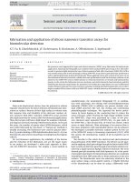
Fig. 1. (Color online) SEM cross-sectional image and photograph of a glass/IZO/CdS/CIS solar cells fabricated by using the FSPD technique.
2. Measurement Details
II. EXPERIMENTS AND DISCUSSION
1. Experimental Details
Substrates: We used glass slides (Germany) (20 mm ×
10 mm of 1 mm (thickness)) to deposit the constituent
films for study their characteristics and deposit the cell
structures. The substrates were cleaned in a neutral detergent solution, rinsed in de-ionized water and dried
prior to depositing the constituent films and cell structures.
Window layer: In-doped ZnO (IZO) films of 200 – 250
nm in thickness were deposited onto the glass substrates.
The deposition was performed by using the USP method
with Zn(CH3 COO)2 dissolved in deionizer water. The
concentration of Zn(CH3 COO)2 in the spray solution
was 0.2 mol/l. Indium was added from InCl3 in a molar
ratio [In]/[Zn] = 0.012, and the deposition temperature
was 420 ± 0.2 ◦ C. The starting solution was atomized at
a frequency of 130 KHz by using an ultrasonic nebulizer.
The solution flow rate was kept at 1.0 ml/min, and nitrogen was used as a carrier gas. The no-zzle-substrate
distance was maintained at about 12 cm.
Buffer layer: CdS thin film of 120 – 130 nm in thickness was directly grown on top of the IZO layer and glass
substrate by using the USP method at a substrate temperature of 380 ± 0.2 ◦ C. The spray solution contained
0.05 M CdCl2 and 0.1 M (NH2 )2 CS solutions. The solution flow rate was kept at 0.8 ml/min, and the other
deposition parameters were kept constant as the window
layer was deposited.
Absorber layer: CIS and CIAS films were created on
the buffer layer and glass substrate. CIS films with thicknesses of 0.5 and 1.5 µm and CIAS films with a thickness
of 1.5 µm were prepared by using the ultrasonic repeated
spray pyrolysis (URSP) technique from an aqueous solution of CuCl2 , InCl3 , (NH2 )2 CS and Al(NO3 )3 , as described in detail in Refs. 7 and 8.
Figure 1 shows a SEM cross-sectional image and photograph of a glass/IZO/CdS/CIS solar cells fabricated
by using the FSPD technique.
The optical transmission of the films was measured
by using a Carry 100, Spectrophotometer in the wavelength range 300 to 800 nm. The thicknesses of the
films were measured using an alpha-step IQ profilometer. The structures of the films were recorded using a
Siemens D5005 diffractometer with Cu-Kα radiation (λ
= 1.54056A◦ ). The conductivity type and the resistivity
of the IZO, CdS, CIS and CIAS films were determined by
using Hall measurement system (7600 Series, Lakeshore,
USA). The photovoltaic performance of the solar cells
was determined by examining the current versus voltage characteristics obtained under simulated AM 1.5 illumination (100 mW/cm2 ) (Keithley 4200-SCS, Saigon
Hi-tech Park R&D Center, Vietnam).
3. Discussion
Figure 2 shows the XRD patterns of the layers in the
cell structures. The results correspond to IZO films having a hexagonal wurtzite structure, and the diffraction
picks were there for ZnO (JCPDS no. 36-1451) as reported in Ref. 9 (see in Fig. 2(a)). The average crystallite
diameter for IZO was about 12 nm, as estimated from
the (002) peak. In Fig. 2(b), the XRD pattern of the CdS
layer is presented. The CdS films can be seen to exhibit a
preferential orientation along the (101) plane, which correspond to the hexagonal phase (JCPDS no. 06-0314)
[6]. The hexagonal CdS film is preferred for solar-cell applications thanks to its excellent stability. The average
diameters of CdS crystallites were about 15 nm when the
CdS thin films were deposited with 120 to 130 nm thicknesses. According to the patterns diffraction (Figs. 2(c)
and 2(d)), the crystalline CIS and CIAS films were characterized by peaks corresponding to (112), (200, 004),
(220, 204), and (312, 116) orientations. Previously reported in Refs. 7 and 8, those main peaks were related
to the tetragonal phase (JCPDS no. 27-0159). With a
CIS film of 2.2 µm thickness, the average diameter of a
CIS crystallite was about 95 nm.
Figure 3 shows plots of transmissions T of the window
layer, of the buffer layer and of the absorber layers. Figure 3(a) presents transmission spectrum of the IZO thin
-1496-
Journal of the Korean Physical Society, Vol. 61, No. 9, November 2012
Fig. 2. XRD patterns of (a) IZO, (b) CdS, (c) CIS, and
(d) CIAS.
Fig. 4. Plots of (αhν)2 versus hν for calculating the optical
band gaps the of the layers.
(Fig. 3) by using the following equation [8,9,11]:
α=−
ln T
,
d
(1)
where d is the film thickness and T is the transmittance.
It is now clear that the IZO, CdS, CIS, and CIAS films
are direct band-gap semiconductors. The absorption coefficient is related to the optical band gap (Eg ) according
to the equation [8,9,11].
(αhν)2 = A(hν − Eg ),
Fig. 3. Optical transmittance spectra of (a) IZO, (b) CdS,
(c) CIS, and (d) CIAS.
film and shows an average transmission of about 80% in
the visible region. The result displays that the IZO film
had a sharp absorption at about 350 nm. For the CdS
buffer layer shown in Fig. 3(b), the spectrum showed an
average transmission of about 78% in the visible region.
The CdS films clearly strong absorption in the region
around 500 nm, which might have a serious effect on the
cells performance. The optical transmissions of the CIS
and the CIAS films are shown in Figs. 3(c) and 3(d).
The transmissions clearly decrease sharply the near IR
region due to the band-gap absorption.
In order to indicate the band gap, we calculated the
absorption coefficient (α) from the transmission data
(2)
where A is a constant and h is the Planck constant. The
band-gap of the films is estimated from plots of (αhν)2
vs. hν by extrapolating the straight line portion of the
plot and finding it intersection with the abscissa. Figure 4 exhibits the optical band-gap of layers in cell structures. We can see that the IZO thin film had an optical
band-gap of about 3.3 eV, the CdS thin film had one of
about 2.42 eV, the CIS film had one of about 1.45 eV,
and the CIAS film had one of about 1.49 eV.
The resistivity, carrier concentrations and mobility of
the IZO, CdS, CIS, and CIAS films were determined using Hall measurements, and the results are presented in
Table 1. The IZO thin film was found to have n-type
conductivity and a low resistivity (10−3 Ωcm). The CdS
thin film exhibited n-type conductivity. Both the CIS
and the CIAS films were found to have p-type conductivity and carrier densities of about 6.04 × 10¹⁶ – 3.34
× 1017 cm−3 .
Fabrication and Characteristics of Fully-sprayed ZnO/CdS/CuInS2 Solar Cells – Tran Thanh Thai et al.
-1497-
Table 1. Hall measurement results.
Sample
IZO
CdS
CIS
CIAS
Resistivity Mobility
(Ω·cm)
(cm2 /V·s)
1.2 × 10⁻³
423.7
19.3
63.8
15.7
41.8
11.3
23.8
Carrier
Type
Density
Conductivity
(cm−3 )
1.92 × 10¹⁹
n
n
8.23 × 10¹³
P
3.34 × 10¹⁷
p
6.04 × 10¹⁶
Table 2. Summary of J-V parameters for the solar cells
depicted in Fig. 5.
Cell
S-1
S-2
S-3
VOC
(mV)
385
395
257
JSC
(mA/cm2 )
6.24
7.01
1.61
FF
(%)
22.12
26.27
20.46
η
(%)
0.53
0.74
0.09
RS
(Ω)
24.1
20.3
32.2
Rsh
(Ω)
72.8
115.3
40.2
Fig. 5. (Color online) Characteristic J-V curves of three
cells: S-1, S-2, and S-3.
Solar cell parameters depend on many variables, each
of which needs control to optimize its value. The properties of the sprayed CIS absorber layer, the most important part of the solar cell, are mainly adjusted by
using the molar ratio [Cu]/[In] in the starting solution.
Thus, a set of full-sprayed glass/IZO/CdS/CIS/metal solar cells was deposited using various starting solution
compositions [Cu]/[In] to grow the absorber layer, keeping other deposition parameters and underlayers invariable. In this study, CuInS2 films with [Cu]/[In] ratios
at 1.0, 1.1, and 1.2 and with constant [S]/[Cu] ratio (=
5) were deposited on glass/IZO/CdS substrates by using
the URSP method. The cells were named S-1, S-2, and
S-3, respectively.
Characteristic J-V curves of the three cells are given
in Fig. 5, and the cell dependences of the outputs on the
[Cu]/[In] ratio in solution are presented in Table 2. In
addition, RS and Rsh were calculated from the illuminated J-V characteristics in Fig. 5.
Fig. 6. Plot of ln (J) versus V for determining the diode
quality factor of solar cell S-2.
A comparison of the data in Table 2 shown that an
rise in the [Cu]/[In] ratio in the starting solution from
1.0 to 1.1 increased the cells output characteristics. Cell
S-2 was observed to exhibit the best parameters. However, cell S-3 based on the CIS absorber prepared with
a [Cu]/[In] ratio of 1.2 exhibited decreased open-circuit
voltage (VOC = 257 mV), short-circuit current density
(JSC = 1.61 mA/cm2 ) and efficiency (η = 0.09%). As
in our previous report in Ref. 12, the Cux S phase was
present in the CIS film deposited at a [Cu]/[In] ratio of
1.2. Therefore, the presence of a high-conductivity Cux S
phase at the CuInS2 /CdS heterojunction is thought to
generate shunt paths, leading to reduced open-circuit
voltages and short-circuit current densities.
The diode quality factor calculated from the dark characteristics of the best cell (S-2) by plotting ln (J) versus
V was 3.4, as shown in Fig. 6. Cell S-1 or S-2 had higher
diode quality factors. This indicates that as reported in
Ref. 1, the dominating generation-recombination process
might be caused by the interface states. In this case, the
series resistance was high (RS = 20.3 Ω), and the shunt
resistance was low, as indicated by the low fill factor.
In order to reduce the series resistance, to increase the
shunt resistance, and to improve the diode quality factor, we made attempts to fabricate solar cells with bilayer
CIS absorber layers. CdS/CIS heterojunctions were prepared using a bilayer structure for the CIS. The preparation process for the junction was as follows: the IZO and
CdS films were deposited on glass substrates by using
the USP method. Next the CIS layer was deposited in
two stages by using the URSP technique. First, a layer of
high-resistance CIS (0.5 µm) was deposited while maintaining the Cu/In ratio in the starting solution at 1.0.
Second, a layer of low-resistance CIS (1.5 µm) was deposited from a solution with a [Cu]/[In] ratio of 1.1 or a
CIAS layer (1.5 µm) was prepared from a solution with
a [Cu]/[In] ratio of 1.0 and an [Al]/[In] ratio of 0.12 by
using the sulfurization process. The CIAS layer was deposited over the high-resistance CIS layer. The cells were
name D-1 (glass/IZO/CdS/CIS (high-resistance)/CIS
-1498-
Journal of the Korean Physical Society, Vol. 61, No. 9, November 2012
Table 3. Summary of J-V parameters for the solar cells
depicted in Fig. 7.
Cell
D-1
D-2
VOC
(mV)
340
425
JSC
(mA/cm2 )
6.65
14.02
FF
(%)
27.39
28.75
η
(%)
0.85
1.71
RS
(Ω)
18.7
10.4
Rsh
(Ω)
95.5
180.1
Fig. 7. Characteristic J-V curves of two cells: D-1, and
D-2.
(low-resistance)/metal) and D-2 (glass/IZO/CdS/CIS
(high-resistance)/CIAS (low-resistance)/metal).
From the J-V characteristics (Fig. 7), the cell parameters were obtained, and the values are given in Table 3.
Among these two types of cells, a better result was obtained for cell D-2.
From the comparison in Fig. 7, the solar cell with bilayer CIS absorber layers clearly showed a significant improvement in the efficiency conversion, and cell D-2 using a bilayer CIS/CIAS absorber layer exhibited the best
solar-cell performance. Its efficiency was 1.71%, which is
higher than that of cell S-2 using a single-layer CIS absorber layer (0.74%) or that of cell D-1 using a bilayer
CIS/CIS absorber layer. Here, the open-circuit voltages
and the short-circuit current density can also be seen to
have improved strongly (Table 3). On the other hand,
the diode quality factor for cell D-2 was 2.5, which was
lower than that of cell S-2. We consider that VOC improvement happened because the optical band gap of
CIAS (1.49 eV) was higher than that of CIS (1.45 eV),
thus enabling a higher Vbi and VOC .
In order to understand the influence of the bilayer
structure of the solar cells based on the CIS absorber
layer, we numerically calculated the band diagrams for
cell S-2 and cell D-2 by using the SCAPS-1D software
[13]. The structure of the modeled solar cell was depicted
schematically in Fig. 1. The band bending in the absorber determined the indicated effective barrier (Φpb ) for
interface recombination. In the case of the dominating
interface recombination, the activation energy (EA ) was
equal to the interface barrier for holes (see in Fig. 8),
which normally is lower than the band gap [1,14]. It fol-
Fig. 8. Band diagrams for (a) single-layer CIS and (b)
bilayer CIS/CIAS based solar cells.
lows from Fig. 8 that Φpb of CIAS (∼500 meV) was higher
than that of CIS (∼380 meV). This is remarkable here,
as the change in the single-layer CIS absorber layer one
to the bilayer CIS/CIAS absorber layer increased the activation energy of the dominant interface recombination
(cell D-02). This is also one of the reasons for the increase in the p-n junction barrier height and led to the
improved cell parameters.
III. CONCLUSION
The important conclusion of this study is that
glass/ZnO/CdS/CIS/CIAS/metal solar cells with a superstrate structure can be deposited by using full spray
pyrolysis deposition (FSPD). We consider that the bilayer CIS/CIAS absorber layers might increase the activation energy of the dominant interface recombination.
This is one of the reasons for the increase in the p-n junction barrier and leads to increases in the solar-cell parameters. The parameters of the solar cell obtained are VOC
= 425 mV, JSC = 14.02 mA/cm2 , FF = 28.75%, and η
= 1.71%. These results show that the FSPD method is a
very promising technique for fabricating solar cells based
on CIS absorbers in a superstrate structure at low cost
and with high efficiency.
Fabrication and Characteristics of Fully-sprayed ZnO/CdS/CuInS2 Solar Cells – Tran Thanh Thai et al.
ACKNOWLEDGMENTS
The authors gratefully acknowledge the financial support of the project KC.05.06/11-15.
REFERENCES
[1] E. Rudigier, Ph.D. Dissertation, Philipps-Universit¨
at
Marburg, Gemany, 2004.
[2] A. Mere, A. Katerski, O. Kijatkina and M. Krunks, in
Proceeding of 19th PVSEC (Paris, France, June 7-11,
2004), p. 1973
[3] M. A. Green, K. Emery, Y. Hishikawa and W. Warta,
Prog. Photovoltaics Res. Appl. 19, 84 (2011).
[4] C. Camus, Ph.D. Dissertation, Freien Universit¨
at Berlin,
Gemany, 2008.
[5] T. Ryo, D-C. Nguyen, M. Nakagiri, N. Toyoda, H. Matsuyoshi and S. Ito, Thin Solid Films 519, 7184 (2011).
[6] V. Bilgin, S. Kose, F. Atay and I. Akyuz, Mater. Chem.
Phys. 94, 103 (2005).
View publication stats
-1499-
[7] T. T. Thai, P. P. Hung, L. T. L. Anh, V. T. Son, V. T.
Bich and D. P. Hai, in Proceeding of 6th SPMS (Danang,
Vietnam, November 8-10, 2009), p. 1235.
[8] T. T. Thai, P. P. Hung, L. T. L. Anh, N. D. Hieu, V. T.
T. Tuyen, N. N. Trung, N. T. T. Nga, V. T. Bich and V.
T. Son, in Proceeding of 6th International Conference on
Photonics and Applications (Hanoi, Vietnam, November
8-12, 2010), p. 365.
[9] M. Krunks and E. Mellikov, Thin Solid Films 270, 33
(1995).
[10] Q. Jijun, J. Zhengguo, Q. Jinwen, S. Yong and W. Weibing, J. Cryst. Growth 282, 421 (2005).
[11] M. H. Badawi. S. Aboul-Enein, M. Ghali and G. Hassan,
Renewable Energy 14, 107 (1998).
[12] T. T. Thai, P. P. Hung, L. T. L. Anh, V. T. Son, V. T.
Bich, C. X. Quan, V. T. T. Tuyen and N. T. Nga, in
Proceeding of 2nd IWNA (Vungtau, Vietnam, November
8-10, 2009), p. 397.
[13] M. Burgelman, P. Nollet and S. Degrave, Thin Solid
Films 361, 527 (2000).
[14] R. Klenk, S. Bakehe, R. Kaigawa, A. Neisser, J. Reiß and
M. Ch. Lux-Steiner, Thin Solid Films 451, 424 (2004).