C3 well performance
Bạn đang xem bản rút gọn của tài liệu. Xem và tải ngay bản đầy đủ của tài liệu tại đây (1.34 MB, 36 trang )
Designed & Presented by
Mr. ĐỖ QUANG KHÁNH, HCMUT
12/2010
Đỗ Quang Khánh – HoChiMinh City University of Technology
Email: or
1
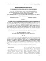
Production & Completion System
System analysis allows PE to both analyze production and design well completion.
(After Mach et al. 1979)
Production & Completion System
Production performance involves matching up the following three aspects:
(1)Inflow performance of formation fluid flow from formation to the wellbore.
(2)Vertical lift performance as the fluids flow up the tubing to surface.
(3)Choke or bean performance as the fluids flow through the restriction at
surface.
Pressure loss distribution.
Production & Completion System
Effect of skin on bottomhole pressure Pwf
Linear flow of liquid through rock
(2.1)
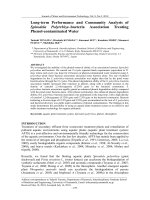
Flow Regimes
Flow Regimes - Comparison
Pressure profile at location r = ri
Pressure
Steady-state Flow
Semisteady-state Flow
Unsteady-state Flow
Time
Time to feel boundary
Assumed well is completed in a circular reservoir with
drainage radius of re, then the time it takes for pressure
transient to reach the boundary is:
(2.2)
ct is the total system compressibility
IPR curves
Single-phase liquid flow
(2.3)
(2.4)
Single-phase gas flow
(2.5)
(2.6)
Single-phase gas flow
(2.7)
(2.8)
Gas PVT data
Gas Well Performance
Rawlins and Schellhardt
(2.9)
(2.10)
Rawlins and Schellhardt analysis
LOG-LOG Plot
or
Slope = 1/n
AOF
Gas flow rate qg
Gas Well Performance
Houpeurt (non-Darcy flow effects)
(2.11)
(2.12)
Gas Well Performance
Houpeurt (non-Darcy flow effects)
(2.13)
Jones, Blount, and Glaze
(2.14)
Graph to determine a and b
or
Slope = b
Intercept = a
Gas flow rate qg
Oil Well Performance
Vogel IPR
(2.15)
Fetkovich
(2.16)
(2.17)
Oil Well Performance
Jones, Blount, and Glaze (non-Darcy effects)
(2.18)
(2.19)
Oil Well Performance
Vogel’s IPR for two-phase flow
(2.20)
(2.21)
(2.22)
Determination of J
J is determination depends on the flowing bottom-hole
pressure of the test point
(2.23)
(2.24)
Wellbore Flow Performance
Pressure drop in the wellbore
(2.25)
Kinetic energy correction factor
For most practical applications, assume W = 0, a = 1
Work done
Irreversible energy losses
(2.26)
Pressure drop in pipe
Pressure drop for any fluid at any pipe inclination:
(2.27)
Flow Through Chokes
Wellhead choke controls the surface pressure and production rate
from a well
Chokes usually are selected so the fluctuations in the line pressure
downstream of the choke have no effect on the production rate
Flow through the choke at critical flow conditions.
The flow rate is a function of upstream or tubing pressure only
(downstream pressure must be approx. 0.55 or less of the tubing
pressure)