POLARIS 10 400 hw inst oper manual MAN 1104 rev 2 6 en GB
Bạn đang xem bản rút gọn của tài liệu. Xem và tải ngay bản đầy đủ của tài liệu tại đây (1.23 MB, 59 trang )
10 20 30 40 50 60 70 80 90 100 110 120 130 140 150 160 170 180 190 200 210 220 230 2 40 250
260 270 280 290 300 310 320 330 340 350 360 370 380 390 400 410 420 430 4 40 450 460 470 480
490 500 510 520 530 540 550 560 570 580 590 600 610 620 630 640 650 660 670 680 690 700 710
720 730 740 750 760 770 780 790 800 810 820 830 8 8 40 850 860 870 880 890 900 910 920 930
940 950 960 970 980 990 1000 1010 1020 1 030 1040 1050 1060 1070 1X080 1090 1100 1110
1120 1130 1140 1150 1160 1170 1180 1190 1200 1210 1220 1230 1240 1250 1260 1270 1280 1290
1300 1310 1 1320 1330 1340 1350 1360 1370 1380 1390 1400 1410 1420 2430 1440 1450 1460
Installation and
Operation Manual
POLARIS
D I G I TA L L A S E R S E N S O R S
Please read and observe!
Keep this manual for future reference.
© LAP GmbH, MAN-1104 Rev. 2.6-en-GB, 2015-01
Translation of the original
POLARIS Laser sensor 10 ... 400
All brand names and product names are trademarks or registered
trademarks of the respective title holder.
© LAP GmbH Laser Applikationen,1999
The reproduction, distribution and utilisation of this document as well
as the communication of its contents to others without express
authorisation are prohibited. Offenders will be held liable for the
payment of damages. All rights reserved in the event of the grant of a
patent, utility model or design.
This document is intended to be used by the owner of the LAP
product, its users and contractual partners of LAP. It must not be
handed to other persons or made available to third parties.
This document is subject to a document content service and subject to
change without prior notice.
LAP GmbH can assume no liability for the correctness, completeness
or up-to-dateness of any laws, regulations or guidelines (e.g. DIN,
VDE, ...) referenced directly or indirectly or quotes taken from such
sources in this publication. We recommend that the complete
regulation or guideline in the latest valid version be consulted for work
to be carried out, where applicable.
Subject to technical changes.
This product complies with European statutory regulations and the
requirements of the European directives. These directives are listed in
the accompanying EC declaration of conformity.
2
© LAP GmbH, MAN-1104 Rev. 2.6-en-GB, 2015-01
POLARIS Laser sensor 10 ... 400
Table of contents
1
General information .........................................................................................................5
1.1
About this document ..............................................................................................5
1.2
Validity ...................................................................................................................6
1.3
Styles and conventions ..........................................................................................7
1.4
2
3
4
1.3.1
Safety instructions ..................................................................................7
1.3.2
Warning and information symbols ..........................................................8
1.3.3
Markups ..................................................................................................8
Intended use ..........................................................................................................9
Safety instructions .........................................................................................................10
2.1
General safety instructions ..................................................................................10
2.2
Safety instructions on the mechanical system ....................................................11
2.3
Safety instructions on electrical equipment .........................................................11
2.4
Safety instructions on lasers................................................................................11
2.4.1
Safety instructions on Laser Class 2 ....................................................12
2.4.2
Safety instructions for Laser Class 3R .................................................12
2.4.3
Safety instructions for Laser Class 3B .................................................13
2.5
Notes on the EMC Directive ................................................................................14
2.6
Employer's liability insurance association regulations .........................................15
2.7
Underlying regulations .........................................................................................15
Goods receipt, transport, storage ................................................................................16
3.1
Goods receipt ......................................................................................................16
3.2
Transport .............................................................................................................16
3.3
Storage ................................................................................................................17
3.3.1
Devices .................................................................................................17
3.3.2
Data medium ........................................................................................18
Technical description ....................................................................................................19
4.1
4.2
4.3
The laser system in use .......................................................................................19
4.1.1
Operating principle ...............................................................................19
4.1.2
Thickness measurement using two laser sensors ...............................21
4.1.3
Converting the sensor value to a measured value...............................22
4.1.4
Dimensions ...........................................................................................23
4.1.5
Technical data ......................................................................................24
4.1.6
Model overview ....................................................................................25
Outputs ................................................................................................................25
4.2.1
Description of the outputs ....................................................................25
4.2.2
Data output format................................................................................26
4.2.3
Cable/Connector pin assignment .........................................................27
4.2.4
Function of LEDs ..................................................................................28
Operating modes .................................................................................................29
© LAP GmbH, MAN-1104 Rev.2.6-en-GB, 2015-01
3
POLARIS Laser sensor 10 ... 400
5
6
4.3.1
Single mode .........................................................................................29
4.3.2
Master-slave mode ...............................................................................29
4.3.3
Multiplex mode .....................................................................................30
Installation ......................................................................................................................31
5.1
General information .............................................................................................31
5.2
Cabling .................................................................................................................31
Initial start-up .................................................................................................................33
6.1
Use of the diagnostic and parametrisation tool ...................................................33
6.1.1
7
Scaling the measured values ...............................................................33
Adjustment and calibration...........................................................................................35
7.1
Laser sensor holder of the laser system .............................................................35
7.1.1
View and structure................................................................................35
7.1.2
Operating principle ...............................................................................36
8
Operation ........................................................................................................................37
9
Care and maintenance...................................................................................................38
10
9.1
Care and maintenance of the system ..................................................................38
9.2
Care and maintenance of the windows ...............................................................38
9.3
Maintenance by LAP ...........................................................................................38
Troubleshooting.............................................................................................................40
10.1
Remedying of faults .............................................................................................41
11
Repair ..............................................................................................................................42
12
Packaging/intermediate storage ..................................................................................43
13
Dismounting/disposal ...................................................................................................44
14
Optional accessories .....................................................................................................45
14.1
14.2
Parametrisation set of the laser system ..............................................................45
14.1.1
DP-SOFT ..............................................................................................45
14.1.2
Power supply unit for the laser sensor .................................................45
14.1.3
RS485-USB converter ..........................................................................45
Interface modules ................................................................................................45
Annex A:
Labelling of the POLARIS laser sensors .....................................................................46
Annex B:
Declaration of conformity .............................................................................................47
Annex C:
Return sheet ..................................................................................................................49
Annex D:
Addresses .......................................................................................................................51
Annex E:
Glossary ..........................................................................................................................52
List of figures ........................................................................................................................................57
Index
4
. ........................................................................................................................................58
© LAP GmbH, MAN-1104 Rev. 2.6-en-GB, 2015-01
POLARIS Laser sensor 10 ... 400
1
General information
1.1
About this document
Dear customer,
This document is designed to help you put your new LAP
product to the best possible use. By observing the information in this document you can avoid potential dangers
and extend your product's service life.
The product has been designed and constructed according to the state of the art, and prior to delivery it has been
checked thoroughly for proper functionality. It may be used
only as intended. Improper use of the system will terminate all warranty claims. The owner alone is responsible
for the risk and any damage or injury.
This document is a component of the product. Keep the
document in a designated location close to the product for
easy reference. If the equipment is moved to a different
operating location make sure the document is transferred
as well.
Read this document carefully prior to installing and
using this product!
Keep this document in a designated location close to the
product for easy reference.
All persons working on or with this product must have
read and understood the relevant sections of the
manual, and in particular the chapter "Safety instructions". The instructions must be observed. The owner
must also inform his/her staff about potential dangers.
The owner must ensure that the document has been
understood. This is the best way to ensure that the
user is as safe as possible.
This document is intended for use by persons with the following knowledge:
•
Qualified technician, mechatronics engineer or similar
qualification.
•
Instruction in laser technology.
If you do not have the requisite knowledge, you should ask
qualified persons or persons who have received appropriate instruction for assistance.
The most important terms used in this document are explained in the glossary.
To effectively use the device, refer to the accompanying
software and the functional description of the DP-SOFT
© LAP GmbH, MAN-1104 Rev.2.6-en-GB, 2015-01
5
POLARIS Laser sensor 10 ... 400
diagnostic and parametrisation tool, hereinafter "diagnostic and parametrisation tool".
Ensure that the version of the parametrisation tool is
at least equal to or higher than the firmware version of
the laser sensor used.
The version number is defined as follows:
Example:
2.3.1.26
Firmware version (see laser sensor documentation)
2 = mechanics revision, 3 = electronics revision
If you have advanced questions about the content of this
operation manual or handling of the device, please contact
your dealer or the regional partner of LAP. The addresses
and contact data of the regional LAP partners are listed in
the annex.
Possible modifications to this product made by users are
not subject to the manufacturer's control. Therefore, always check whether the information in this documentation
matches the actual product technology before operating or
using the device. In case of deviations or unclear issues,
please contact us immediately. This is in your own interest
as well.
The instructions given to you by LAP service staff take
precedence over this document.
We aim to continuously improve the quality of our documentation. If you have any questions or requirements with
regard to this document, please contact us at
1.2
Validity
This document is valid for:
•
6
POLARIS Laser sensor 10 ... 400
© LAP GmbH, MAN-1104 Rev. 2.6-en-GB, 2015-01
POLARIS Laser sensor 10 ... 400
1.3
Styles and conventions
This chapter describes conventions as used in this operation manual. Read this chapter to make it easier for you to
use this operation manual.
1.3.1
Safety instructions
This operation manual uses a multi-level system to notify
the reader of different degrees of hazards.
DANGER
Cause of the danger
Signals that death or severe physical harm will result if the
specified precautions are not observed.
WARNING
Cause of the danger
Signals that death or severe physical harm may result if
the specified precautions are not observed.
CAUTION
Cause of the danger
Signals, that minor physical injury may result if the
specified precautions are not observed.
Notice
Signals that property damage can occur or indicates important information on handling the product or important
sections of the document.
© LAP GmbH, MAN-1104 Rev.2.6-en-GB, 2015-01
7
POLARIS Laser sensor 10 ... 400
1.3.2
Warning and information symbols
In addition to the general danger symbols, we also use the
following pictograms in this operation manual in order to
point out specific hazards.
DANGER
Electric voltage
Signals danger to life or limb with permanent physical
damage due to electric voltage.
WARNING
Laser beams
Signals physical harm with permanent physical damage
due to laser beams.
Please also note the following information symbols:
Manufacturer
Fragile, handle with care!
Serial number of the devices
Keep dry!
Do not dispose of the device with regular domestic waste.
We offer a return service.
Please refer to the return sheet in the annex.
1.3.3
Markups
We use the following markups in this operation manual:
Markup
●
Bulleted list.
General list or instruction in no particular order.
1.
Numbered list.
Operating steps which need to be
performed in the order listed.
Tab. 1-1:
8
Usage
Markups
© LAP GmbH, MAN-1104 Rev. 2.6-en-GB, 2015-01
POLARIS Laser sensor 10 ... 400
1.4
Intended use
POLARIS laser sensors are used to measure the distance
or the thickness of standing or moving objects. They can
be installed permanently in or on a machine or building
structures directly using the bracket provided.
Any other use is not permitted. The owner bears sole responsibility for the consequences of improper use.
Intended use also includes adhering to our instructions regarding installation, removal, commissioning, operation,
maintenance and disposal of the system.
The operating staff must immediately notify the owner or
his/her representative of any safety-relevant changes to
the system.
As a basic rule, any intended changes to the device must
be approved in writing by LAP.
© LAP GmbH, MAN-1104 Rev.2.6-en-GB, 2015-01
9
POLARIS Laser sensor 10 ... 400
2
Safety instructions
2.1
General safety instructions
Safety instructions are intended to ensure occupational
health and safety and the prevention of accidents. They
must be heeded.
In order to protect you and your colleagues against injury,
we need your co-operation, too. Therefore be careful at
work all the times. Always be aware that dangers are usually "not obvious".
In order to ensure safe operation, the owner must make
sure that the persons working on or with the device are informed about the possible dangers of laser radiation.
Only qualified authorised personnel who have received
appropriate instruction may work with/on the laser system
described in this manual.
The person who operates this laser system must have
read and understood the relevant sections of the operation
manual.
A copy of this operation manual must always be kept in a
designated location close to where the laser system is
used.
Safety-relevant changes to the laser system must be reported immediately to the persons responsible.
The user must make sure that unauthorised persons remain outside the work area of the laser system.
Users, fitters and maintenance technicians must be given
instruction on all safety-relevant aspects of the laser system by the owner on a regular basis. The same applies to
safety regulations that are to be observed at the user's
premises and are not included in this operation manual.
The applicable national and local safety regulations as
well as the safety regulations of the user must be strictly
observed when operating or making interventions in the
system.
If a malfunction occurs, the laser beam may stray outside
the designated zone.
Use only accessories approved by LAP.
Steps have been taken at the development stage to ensure maximum protection of the user through the design of
the laser and integrated safety devices. However, this
does not relieve the user of the obligation to observe
his/her general duty of care.
10
© LAP GmbH, MAN-1104 Rev. 2.6-en-GB, 2015-01
POLARIS Laser sensor 10 ... 400
Notice
In the event of malfunctions, the equipment is to be
switched off immediately and the owner or his/her representative are to be informed.
The device contains highly sensitive components. Therefore, under no circumstances should you attempt to repair
it yourself.
2.2
Safety instructions on the mechanical system
Only use the mounting bracket provided. Do not drill into
the components. If the installation is carried out incorrectly
this could impair the measurement accuracy and damage
the device. In the worst case the device could come loose
and cause injury.
2.3
Safety instructions on electrical equipment
In the event of malfunctions in the electrical supply, the
device is to be switched off immediately.
Works on the device's electric system may be carried out
only by a skilled electrician.
Notice
The laser contains highly sensitive parts. Therefore, under
no circumstances should you attempt to repair the laser
yourself.
2.4
Safety instructions on lasers
WARNING
Potential danger of exposure to radiation
Use of operating or adjusting equipment or performance of
procedures other than those specified in this document
may result in hazardous radiation exposure.
•
Never use a different procedure than the ones described in this document.
If you cannot guarantee compliance with the above, you
must not carry out the work described in this document.
Get in touch with LAP to make corresponding arrangements contact information on p. 51.
According to DIN EN 60825-1, lasers are classified into
classes 1, 1M, 2, 2M, 3R, 3B and 4.
© LAP GmbH, MAN-1104 Rev.2.6-en-GB, 2015-01
11
POLARIS Laser sensor 10 ... 400
Laser class of product (depending on version):
•
2
•
3R
•
3B
The laser class is shown on the laser warning label of the
device.
2.4.1
Safety instructions on Laser Class 2
Fig. 2-1:
Laser warning sign class 2 (example)
CAUTION!
Risk of injury due to exposure to the laser beam of
class 2 lasers
Up to a radiation time of 0.25 s these lasers can be considered harmless. The accessible laser radiation is limited
to the visible spectral range.
2.4.2
•
Never look directly into the laser beam.
•
Close your eyes immediately and turn away if the
beam strikes your eye.
•
Prevent specular reflections.
•
Never point the laser beam at people's faces.
Safety instructions for Laser Class 3R
These are lasers that deliver a medium power output.
Fig. 2-2: Laser warning sign class 3R (example)
12
© LAP GmbH, MAN-1104 Rev. 2.6-en-GB, 2015-01
POLARIS Laser sensor 10 ... 400
WARNING!
Risk of injury due to exposure to the laser beam of
class 3R lasers
Class 3R laser devices are potentially dangerous to the
eyes. The risk of eye damage is reduced because the
maximum accessible radiation in the visible wave length
range is restricted to five times the limit value of the accessible radiation for class 2, and, in the remaining wave
length range, to five times the limit value of the accessible
radiation for class 1.
2.4.3
•
Never look directly into the laser beam.
•
Close your eyes immediately and turn away if the
beam strikes your eye.
•
Prevent specular reflections.
•
Never point the laser beam at people's faces.
•
Never look into the laser beam with optical instruments (e.g. magnifying glasses).
•
Limit the laser beam to the necessary work area.
•
Train operating and maintenance staff in the handling
of lasers.
Safety instructions for Laser Class 3B
These are lasers that deliver a medium power output.
Fig. 2-3: Laser warning sign class 3B (example)
© LAP GmbH, MAN-1104 Rev.2.6-en-GB, 2015-01
13
POLARIS Laser sensor 10 ... 400
WARNING!
Risk of injury due to exposure to the laser beam of
class 3B lasers
The eyes will be injured due to exposure to the laser beam
of class 3B lasers. Diffuse scattered radiation can be considered harmless providing the observation distance is not
less than 13 cm and the observation time is not more than
10 s.
•
Wear laser safety glasses while working at the laser
and in the laser area.
•
Never look directly into the laser beam.
•
Close your eyes immediately and turn away if the
beam strikes your eye.
•
Prevent specular reflections.
•
Never point the laser beam at people's faces.
•
Never look into the laser beam with optical instruments (e.g. magnifying glasses).
•
Limit the laser beam to the necessary work area.
•
Train operating and maintenance staff in the handling
of lasers.
•
Mark the laser work area using the laser warning sign.
•
Prevent unauthorised persons from entering rooms
where the open-beam laser is operated. Identify the
rooms with “No Access” signs.
•
Ensure that operation of the laser is displayed via a
visual warning that can be seen from a distance.
•
Secure lasers against unauthorised access using a
lockable master switch, for example, using a keyoperated switch.
National requirements
In addition to the requirements of EN 60825-1:2007, the
respective national occupational safety and health requirements for lasers must be reviewed and implemented.
2.5
Notes on the EMC Directive
The product has been developed and tested on the basis
of Directive 2004/108/EC. Make sure that the product is
installed in accordance with the installation manual and in
compliance with EMC guidelines. Our product complies
14
© LAP GmbH, MAN-1104 Rev. 2.6-en-GB, 2015-01
POLARIS Laser sensor 10 ... 400
with the limits specified in this standard for electromagnetic disturbance and immunity. Disturbances of other devices are thus not to be expected. However, other devices in
the vicinity may not comply with these limits and might
therefore interfere with our product. This particularly applies to mobile radio communication devices. This could
lead to malfunctions. Therefore ensure that all devices located in the operating area comply with the legal limits.
Make sure that the devices are marked with the CE label
and that they have a valid declaration of conformity.
If our product does not behave as described in the operation manual, switch it off immediately and inform the owner
or the person acting on his behalf. Under no circumstances should you try to remedy the malfunction yourself. Do
not modify the product.
2.6
Employer's liability insurance association regulations
If you are using the device within the jurisdiction of the
Federal Republic of Germany, you must observe the following "Berufsgenossenschaftlichen Vorschriften" (regulations issued by the Employer's Liability Insurance Association):
2.7
•
BGV A3 "Elektrische Anlagen und Betriebsmittel"
•
BGV A8 "Sicherheits- und Gesundheitsschutzkennzeichnung am Arbeitsplatz"
•
BGV B2 "Laserstrahlung"
Underlying regulations
•
Production processes: DIN EN ISO 9001.
•
Laser safety: DIN EN 60825-1.
•
Electrical safety: DIN EN 61010-1.
•
EMC: DIN EN 61326-1.
© LAP GmbH, MAN-1104 Rev.2.6-en-GB, 2015-01
15
POLARIS Laser sensor 10 ... 400
3
Goods receipt, transport, storage
3.1
Goods receipt
Make sure that:
•
The type and serial numbers on the type plates of the
products match the information on the order and delivery papers, (see Annex A: on page 46).
•
The delivery is complete (compare with the delivery
note).
•
All parts are in a proper condition and undamaged.
Notice
Notify LAP immediately in writing about any transport
damage and/or missing parts and include your address
and the order number.
Following the incoming goods inspection, store the components in their transport packaging until they are installed. Observe the storage conditions specified in chapter 3.3 on page 17.
During transportation, the products are protected against
moisture by a plastic film. Do not remove the film until the
temperature of the products has adjusted to room temperature. This prevents the condensation of water on or in the
product. When in doubt, wait for 24 hours before unpacking.
Retain the packaging in case it is necessary to transport
the equipment at a later date. Dispose of the packaging if
necessary in accordance with the local regulations.
3.2
Transport
CAUTION
The components contain highly sensitive parts which must
be particularly protected against shock during
transport/shipping.
If you need to ship components, use the original LAP
packaging if possible.
Transport the laser sensors carefully to avoid damage due
to collisions. The laser devices contain sensitive glass
components.
16
© LAP GmbH, MAN-1104 Rev. 2.6-en-GB, 2015-01
POLARIS Laser sensor 10 ... 400
3.3
Storage
3.3.1
Devices
CAUTION
Ensure that the parts are not exposed to water or condensing moisture.
Notice
Please note that in case of non-adherence to the ambient
conditions the warranty will become void.
The storage rooms must be dry, dust-free, and free of aggressive gases (e. g. acid vapours, ammoniac or hydrogen
sulphide). They must be protected against low temperatures (frost-free).
Please note:
•
Humidity and aggressive gases can cause corrosion.
•
Electronic components, motors, bearings and seals
may be damaged if subjected to excessive temperature fluctuations.
When putting the equipment into storage, protect open
plug connections from dust and moisture.
The following climatic conditions must be satisfied when
putting the equipment into storage:
Storage conditions
Ambient temperature
0 °C to +80 °C
Humidity
35% to 85% rel. humidity, noncondensing
Tab. 3-1:
Hardware storage conditions
© LAP GmbH, MAN-1104 Rev.2.6-en-GB, 2015-01
17
POLARIS Laser sensor 10 ... 400
3.3.2
Data medium
When storing the data medium, these climatic storage
conditions must be met:
Storage conditions
Ambient temperature
0 °C to +40 °C
Humidity
35% to 85% rel. humidity, noncondensing
Light irradiation
No direct sunlight
Tab. 3-2:
18
Storage conditions data medium
© LAP GmbH, MAN-1104 Rev. 2.6-en-GB, 2015-01
POLARIS Laser sensor 10 ... 400
4
Technical description
4.1
The laser system in use
POLARIS laser sensors are used to measure the distance
or the thickness of standing or moving objects. By using
this measurement system, you can monitor your production completely and document the quality of the product for
the customer with production logs.
The laser sensors are suitable for industrial applications.
They can be used in any production situation to test individual parts in the laboratory and for online production
control. Impacts to the devices and scratches on the protective glass panels could impair the functionality of the
devices and must be avoided.
The laser sensors operate with a max. sampling rate of 4
kHz. Both digital and analog measurements are output.
For diagnostic purposes, a video signal can be evaluated
using the diagnostic and parametrisation tool.
Several lasers can be operated at one RS485 interface.
The laser sensor parameters can also be checked and
modified via this RS485 interface. For this operating
mode, however, each sensor must first be assigned a dedicated address. The diagnostic and parametrisation tool is
used for this purpose.
Some of the accessories offered by LAP:
4.1.1
•
Laser sensor holder (see chapter 7.1) for installing
and removing the POLARIS laser sensors easily
•
RS485 / USB converter for connecting the POLARIS
laser sensors to a USB interface
•
Interface modules (see chapter 14.2) for processing
binary and analog signals as well as for connecting
encoders to the RS485 network.
•
User software for processing measurements and visualizing several laser sensors.
•
Complete, customer-specific solutions.
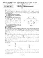
Operating principle
The measuring principle of the POLARIS laser sensors is
based on the laser triangulation principle. A laser beam
generates a point of light on the measured object which is
imaged by a lens on a CCD line mounted to one side of
the laser.
© LAP GmbH, MAN-1104 Rev.2.6-en-GB, 2015-01
19
POLARIS Laser sensor 10 ... 400
Depending on the distance between laser and measured
object, the position of the exposed pixels on the CCD line
changes.
The exposed pixels are evaluated and the dimension of
the relevant object status is determined by processing signals via a digital signal processor (DSP).
The calculated distances are output or queried via the
RS485 bus and the analog output.
In addition, the limit values of the measured values can be
monitored. To this end, two limit value outputs are implemented whose respective limit values can be set in the diagnostic and parametrisation tool under "Filters / Limit
Values".
All objects which are neither very reflective nor transparent
can be measured.
1
Laser
2
CCD line
3
Receiver lens
4
Measuring range
5
Measuring distance
Fig. 4-1:
Measuring principle (diagram)
The computer used for the diagnostic and parametrisation
tool software must have an RS485 interface, e.g. the USBto-RS485 adapter from LAP. For further information
please refer to chapter 14.1 of this operation manual.
Information on the wiring of the laser sensors and the
functions of the display LEDs is presented in chapter
4.2.4.
The POLARIS laser sensors can also be operated via the
digital intermediate transfer module POLARIS CONNECT
or POLARIS HUB module. For notes and information on
this, refer to the corresponding description of functions
and operation.
20
© LAP GmbH, MAN-1104 Rev. 2.6-en-GB, 2015-01
POLARIS Laser sensor 10 ... 400
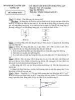
4.1.2
Thickness measurement using two laser sensors
Thickness measurements are possible using two
POLARIS laser sensors. In this case the user must ensure
that the surface of the measured object never leaves the
measuring range of the corresponding laser sensor on either side of the measured object (see Fig. 4-1: Representation of the measuring ranges).
Each laser sensor must therefore be mounted so that the
end of its measuring range covers the surface of the
measured object at the farthest possible distance.
The measured value 0 corresponds to the point farthest
away. The measured values increase towards the POLARIS.
In the marginal case of an absolutely flat, extremely thin
measured object, the clear width is the sum of the distances of both ends of the measuring range.
The middle of the measuring range and the clear width are
shown in the following diagram for the sake of clarification.
1
Reference surface
2
Measuring distance
3
Start (upper sensor) and end (lower sensor) of measuring range
4
Middle of the measuring range
5
End (upper sensor) and start (lower sensor) of measuring range
6
Clear width for thickness measurement
7
Measured object
Fig. 4-1:
Representation of the measuring ranges
The installation dimensions for the respective model sizes
are listed in the following table.
© LAP GmbH, MAN-1104 Rev.2.6-en-GB, 2015-01
21
POLARIS Laser sensor 10 ... 400
Measuring
Type
range
(mm)
Measuring distance = start of
measuring
range (mm)
Middle of
measuring
range
(mm)
Clear width beEnd of
tween the laser
measuring
sensors for thickrange
ness measurement
(mm)
(mm)
10
10
51
56
61
112
30
30
100
115
130
230
70
70
190
225
260
450
130
130
220
285
350
570
250
250
380
505
630
1010
400
400
440
640
840
1280
Tab. 4-1:
POLARIS installation dimensions
Note regarding thickness measurement: Add the minimum
product thickness to the clear width.
4.1.3
Converting the sensor value to a measured value
The value range of the sensors is 2768 to 62768 and is
independent of the sensor's measuring range. The value
2768 corresponds to the end of the measuring range that
is farthest away from the sensor and the value 62768 corresponds to the end that is closest to the sensor.
The actual measured value in mm is obtained by subtracting 2768 from the sensor value and then multiplying the
difference by the sensor's measuring range and dividing
by the resolution (60000). The following equation can be
used:
Fig. 4-2:
Measured value formula
This yields the settings for the Wetec display converter:
•
Scale factor = measuring range / 60000
•
Offset = 2768 x measuring range / 60000
This results in the following for the inverse representation
of the measured value:
Fig. 4-3:
22
Measured value formula (inverse)
© LAP GmbH, MAN-1104 Rev. 2.6-en-GB, 2015-01
POLARIS Laser sensor 10 ... 400
This yields the settings for the Wetec display converter:
•
Scale factor = -measuring range / 60000
•
Offset = 62768 x measuring range / 60000
Factors for the standard measuring ranges:
Descending
Measuring
range
4.1.4
Scale
factor
Offset
Ascending
Scale
factor
Offset
2
0.0000333
-0.0923
-0.0000333
2.092
10
0.0001667
-0.4613
-0.0001667
10.461
30
0.0005000
-1.3840
-0.0005000
31.384
70
0.0011667
-3.2293
-0.0011667
73.229
130
0.0021667
-5.9973
-0.0021667
135.997
250
0.0041667
-11.5333
-0.0041667
261.533
400
0.0066667
-18.4533
-0.0066667
418.453
Tab. 4-2:
Scale factors for standard measuring ranges
Fig. 4-4:
Dimensions of the POLARIS laser sensor
Dimensions
© LAP GmbH, MAN-1104 Rev.2.6-en-GB, 2015-01
23
POLARIS Laser sensor 10 ... 400
4.1.5
Technical data
Property
Value
Operating voltage
18 … 30 VDC
Current consumption
Max. 250 mA
Laser power
1 mW (optional 3 … 7 mW)
Laser class
2, 3R or 3B; observe laser warning label
Laser source
Laser diode 670 nm (red)
Life expectancy
more than 30,000 hours of operation
(at T=25 °C)
Measuring frequency
300 Hz ≤ 4 kHz
Data formats
SynchroNet, FastBin, ASCII decimal
Interface
RS485, opto-isolated, up to 960 kBaud
Contacting
Coninvers connector, 9-pin
4 … 20 mA
Analog output
Max. burden 470 Ω
Limit value outputs
≤ 50 mA, common feed Vcc
International Protection
IP65
Rating
Dimensions L x W x H
168 x 109 x 39 mm
Weight
1100 g
Ambient light
(operation)
≤ 3000 Lux
Ambient temperature
(operation)
0 °C to +40 °C
Humidity
(operation)
35% to 85% rel. humidity, non-condensing
Tab. 4-3:
General POLARIS data
Comments regarding measuring frequency: With the default factory settings, the POLARIS DSP controls both the
laser power and, if that is insufficient, the exposure time of
the CCD line in real time to obtain the optimum measurement results. If the application requires, a fixed exposure
time of 250 µs is possible.
24
© LAP GmbH, MAN-1104 Rev. 2.6-en-GB, 2015-01
POLARIS Laser sensor 10 ... 400
4.1.6
Model overview
Repeat
accuracy
(over
time)*
[μm]
Model/type
MeasurMeasuring dising range
tance
[mm]
[mm]
POLARIS 10
10
51
0.2
± 0.4
± 1 / 0.01
100 / 280
POLARIS 30
30
100
0.5
± 1.0
± 3 / 0.01
120 / 350
POLARIS 70
70
190
1.0
± 1.5
± 7 / 0.01
140 / 380
POLARIS 130
130
220
2.0
± 3.0
± 13 / 0.01
170 / 420
POLARIS 250
250
380
4.0
± 7.0
± 25 / 0.01
200 / 700
POLARIS 400
400
440
6.0
± 10.0
± 40 / 0.01
250 / 840
Resolution
[μm]
Measuring uncertainty
[μm]*/%**
Min. /Max.
measuring
point width
[μm]
* Derived from DIN 32877, averaging of 64 individual values **In % of
the measuring range
Tab. 4-4:
POLARIS measuring ranges and basic clearances
Comments:
•
Special measuring ranges are possible on request in
addition to the indicated measuring ranges.
•
The resolution, repeat accuracy and measuring uncertainty refer to transmission via the RS485 interface.
•
The repeat accuracy and measuring uncertainty refer
to an ambient temperature of 20°C, measured on a
matt white surface and an integration time of 100ms,
2σ.
•
Repeat accuracy derived from DIN 32877, averaging
of 64 individual values
•
The percentage value for the measuring uncertainty
refers to the entire measuring range.
•
Measuring point width: Dimension of the spot parallel
to the laser sensor cover.
4.2
Outputs
4.2.1
Description of the outputs
An RS485 bus, a limit value output and an analog output
are provided as outputs.
© LAP GmbH, MAN-1104 Rev.2.6-en-GB, 2015-01
25