quá trình khí hóa ở nhiệt độ cao của gỗ và than bùn
Bạn đang xem bản rút gọn của tài liệu. Xem và tải ngay bản đầy đủ của tài liệu tại đây (2.79 MB, 11 trang )
Journal of the European Ceramic Society xxx (xxxx) xxx–xxx
Contents lists available at ScienceDirect
Journal of the European Ceramic Society
journal homepage: www.elsevier.com/locate/jeurceramsoc
Original Article
Exposure of refractory materials during high-temperature gasification of a
woody biomass and peat mixture
⁎
Markus Carlborgb, Fredrik Weilanda, , Charlie Mac, Rainer Backmanb, Ingvar Landälvc,
Henrik Wiinikkaa,c
a
b
c
RISE Energy Technology Center, S-941 28 Piteå, Sweden
Umeå University, S-901 87 Umeå, Sweden
Luleå University of Technology, S-971 87 Luleå, Sweden
A R T I C L E I N F O
A B S T R A C T
Keywords:
Gasification
Oxygen blown
Biomass
Entrained flow
Slag
Refractory
Finding resilient refractory materials for slagging gasification systems have the potential to reduce costs and
improve the overall plant availability by extending the service life. In this study, different refractory materials
were evaluated under slagging gasification conditions. Refractory probes were continuously exposed for up to
27 h in an atmospheric, oxygen blown, entrained flow gasifier fired with a mixture of bark and peat powder. Slag
infiltration depth and microstructure were studied using SEM EDS. Crystalline phases were identified with
powder XRD. Increased levels of Al, originating from refractory materials, were seen in all slags. The fused cast
materials were least affected, even though dissolution and slag penetration could still be observed.
Thermodynamic equilibrium calculations were done for mixtures of refractory and slag, from which phase assemblages were predicted and viscosities for the liquid parts were estimated.
1. Introduction
Biomass gasification can become a part of future energy systems for
the production of sustainable transportation fuels, chemicals and
power. Among gasification technologies, the entrained flow technology
currently under development for biomass produces the highest quality
syngas, i.e. tar free syngas mainly composed of CO and H2, [1–3].
Furthermore, most industrial coal gasification plants developed after
1950 are of the entrained flow type [1]. Entrained flow gasifiers are
generally operated in slagging mode, meaning that the operating temperature is above the ash melting point of the feedstock. At this temperature, tars are destructed and fuel conversion is almost complete.
The high operating temperature comes however with the penalty of
relatively high oxygen consumption. Nevertheless, different types of
reactor walls have been developed for coal gasifiers to protect the reactor shell from the harsh conditions of the reaction zone. The refractory wall is the simplest, most efficient and lowest-cost design [1].
Here, a hot face refractory material, which can withstand the temperature and chemical conditions inside the gasifier, is installed together with one or more insulating layers (back-up layers) inside the
reactor. High quality chromium oxide and/or zirconium oxide based
refractories are employed in coal gasifiers because of their chemical
resistance to the coal ash. Another type of wall is the water-cooled
⁎
membrane wall, which during operation is covered by a layer of solid
slag over which the liquid slag will flow. This type of wall has the
advantage that it is extremely durable. Almost no corrosion will occur
because the membrane wall only comes in contact with solidified slag.
Drawbacks are, however, high investment cost and higher heat loss
(2–4%) compared to refractory walls (1%) [1] which significant reduces the gasification efficiency.
Despite this, slagging gasification systems employing refractory
walls report refractory life-times of only 6–18 months [1] and extensive
research has been performed to address material issues in slagging coal
gasifiers. The mechanisms for refractory degradation are related to slagrefractory interactions and include chemical dissolution, mechanical
erosion, chemical and structural spalling [4–9]. The development of
refractories for coal gasifiers continues to be active, and indicates that
the development of refractories for entrained flow gasification of woody
biomass must be considered as part of the overall development process.
This is heightened by the fact that woody biomass is generally enriched
in elements such as Ca, K and Mg whereas coal typically has higher
contents of Al-, Fe-, Si- and Ti-bearing minerals [10]. Since the ashforming matter in biomass and coal differ considerably, which thereby
also changes the melting and wetting characteristics of the slags [11],
refractory materials developed for coal slags are not necessarily resistant to the likely more alkaline woody biomass slags (e.g. [12] and
Corresponding author.
E-mail address: (F. Weiland).
/>Received 28 June 2017; Received in revised form 4 September 2017; Accepted 11 September 2017
0955-2219/ © 2017 Elsevier Ltd. All rights reserved.
Please cite this article as: Carlborg, M., Journal of the European Ceramic Society (2017),
/>
Journal of the European Ceramic Society xxx (xxxx) xxx–xxx
M. Carlborg et al.
shown in Table 1 together with the calculated composition of the fuel
mixture. The pulverized fuel mixture was collected in big-bags, where it
was stored awaiting the gasification experiments. Fuel powder was
pneumatically transported from the big-bags to the receiving fuel
hopper. This experimental campaign included 42 h of gasifier operation. Refueling of the hopper was repeated every 12 h. During these
time periods, the gasification process was paused by introducing a small
purge flow of N2 through the gasifier while fuel and O2 feeding was
stopped.
Prior to campaign startup, the gasifier was preheated over night
with a ∼100 kW oil burner firing conventional diesel fuel. Additional
heating was accomplished by combusting the pulverized fuel mixture
until the refractory temperature in the gasifier reached close to 1200 °C.
Once this temperature was reached, the probes holding the ceramic
samples were installed in the gasifier directly followed by reducing the
O2 feeding rate in order to switch the operation to gasification. Fuel
powder was fed to the gasifier using constant mass flow of transportation air corresponding to 220 ± 10 NL/min (average ± standard
deviation). Fuel feeding rate was 25 ± 3 kg/h, whereas the O2 feeding
rate (174 ± 8 NL/min) was used to control the process temperature
and maintain a temperature of approximately 1100–1140 °C on the
refractory thermocouples that were positioned closest to the sample
probes, i.e. T13 in Fig. 1. Pilot gasifiers generally have higher proportional heat losses compared to industrial full-scale gasifiers. In order to
achieve a certain gasification temperature, pilot gasifiers must therefore
be operated with relatively higher oxygen feed. Thus, the gasifier used
in this work was operated at an oxygen stoichiometric ratio, λ, of
0.47 ± 0.02 during the gasification experiment. The resulting process
temperatures and syngas composition are found in Tables 2 and 3, respectively.
references therein). There is a lack of studies concerning the degradation of refractories caused by interaction from ash derived from biomass, while previous experiences from a pilot-scale reactor lined with
mullite-based refractory indicated detrimental interactions with woody
biomass ash that led to fluxing of the refractory and blockage of the
reactor outlet [13].
Additional knowledge is therefore needed towards understanding
biomass slag-refractory interactions and to develop resilient refractory
materials for slags with origins from biomass. The present study focused
on evaluating the degradation of eight different refractory materials
after they were exposed to gasification of a woody biomass and peat
mixture in a pilot gasifier. The purpose of these exposures was to
identify critical refractory properties (e.g., compositions and microstructures) that should be pursued in the development of a refractory
for woody biomass gasifiers. The refractories were chosen from commercially available materials, ranging from cheap castables to expensive fused cast materials, and selected based on the project group’s
previous experiences from gasification of black liquor [14] and stem
wood biomass [13]. In this work, we present the results from the evaluation including some conclusions and suggestions on refractory materials for slagging woody biomass gasifiers.
2. Experimental
2.1. The gasifier
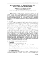
An atmospheric entrained flow pilot gasifier was used for the experiments, see Fig. 1. The gasifier has an inner diameter of 50 cm and a
height of approximately 3.9 m. It was previously described in [15], and
therefore only a brief overview is given herein. Pulverized fuel was
pneumatically transported from a fuel hopper to the burner mounted on
top of the gasifier. The fuel feeding rate was controlled by the rotational
speed of fuel dosing screws. Fuel entered the gasifier together with
transport air through an Ø 50 mm central exit of the burner. Oxygen
(O2) was controlled by a mass flow controller and injected through four
Ø 3.5 mm inlets concentrically positioned and evenly distributed 90°
apart outside of the fuel exit. The four O2-inlets are directed so that the
attack angle was 45° towards the central axis. This created a jet flame in
the central part of the gasifier. Insulating refractory lining protect the
outer steel shell from the hot gasification environment. The refractory
hot-face being exposed to the gasification environment was Gouda Vibron 160H (90 mm thick). Temperature monitoring was performed by
thermocouples at eight different levels along the reactor, separated
approximately 40 cm in height according to Fig. 1. Eight thermocouples
were positioned in the gas phase (T1–T8) and eight in the refractory
(T9–T16), with the tip approximately 20 mm from the hot face wall.
Gas phase thermocouples were protected by ceramic encapsulation (Ø
8 mm) and were of type-S (T1–T4) and type-K (T5–T8). Refractory
thermocouples were all of type-K.
Syngas was continuously sampled from the bottom part of the gasifier as indicated in Fig. 1. The resulting syngas composition was
monitored by a Micro-GC (Varian 490 GC) with molecular sieve 5A and
PoraPlot U columns followed by TCD (thermal conductivity detector)
detectors for detection of H2, N2, O2, CO, CO2, CH4, C2H2, C2H4 and
C2H6.
2.3. Exposure of ceramics
Eight different materials, that are commercially available and used
in different refractory applications, were chosen for this study. Material
specifications can be found in Table 4.
Refractory samples were cut as cuboids with dimensions
13 × 13 × 110 mm. Each sample was fitted with boiler cement into a
rectangular Al2O3 tube (20 × 20 mm outer dimensions and 3 mm wall
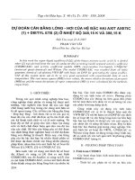
thickness) that were mounted at the probe tip, see Fig. 2. The purpose
of the rectangular tube was to reduce the conductive cooling effect from
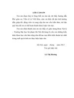
the probe itself. Eight water cooled sample probes were used simultaneously during the experiment. Fig. 3 is a photo taken from the top of
the gasifier showing the probes installed inside the reactor during gasification. The locations of the probes were chosen as approximately
representative of the average conditions inside the gasification zone.
Two of the probes were equipped with type-S thermocouples for temperature measurement at the rear end of the cuboid sample (Fig. 2).
Average temperatures measured by these thermocouples are also shown
in Table 2. Probe temperatures were generally lower, and showed
greater variation than surrounding refractory thermocouples. This was
most probably an effect of the water cooling of the probes.
This investigation included two sample pieces of each refractory
material. The first sample piece of each refractory material was exposed
to slagging gasification during 6 h, whereas the second round of samples, except graphite and top piece of HB-sample, were installed in the
gasifier for 26 h. This included approximately 2.5 h of paused operation
during hopper refueling and approximately 1 h in combustion mode
during heat-up after refueling. The second graphite sample was heavily
affected and therefore removed in conjunction with refueling already
after 7 h of exposure. Once a graphite sample was removed from the hot
reactor, it was allowed to cool down in a nitrogen purged sample holder
in order to avoid further combustion in the surrounding air. The top
piece of the second HB-sample broke and fell down into the boiler part
of the plant after being exposed under gasification conditions for 11 h
and 45 min. All other samples were just removed from the gasifier and
2.2. Fuel and experimental conditions
The feedstock was prepared by mixing a bark fuel from
Glommersträsk, Sweden, with peat from Norrheden, Sweden. This fuel
mixture was chosen based on a previous study that showed that bark
fuel alone would not form a flowing slag at typical wall temperatures of
1200–1250 °C [16]. Estimations indicated a flowing slag could be
formed under the mixing proportion of 70 wt% bark and 30 wt% peat.
The fuel mixture was milled in a hammer mill with sieve size of
1.25 mm directly after blending. The individual fuel compositions are
2
Journal of the European Ceramic Society xxx (xxxx) xxx–xxx
M. Carlborg et al.
Fig. 1. Schematic overview and picture of the gasifier with probes positions clearly marked.
thermochemical equilibrium and viscosity calculation in order to aid
interpretation of the experimental results. The pure phase and solution
databases selected were FactPS and FToxid (SLAGA, MeO_A, cPyrA,
oPyr, pPyrA, LcPy, WOLLA, aC2SA, Mel_A, OlivA, Cord, CAFS, CAF6,
CAF3, CAF2, CAF1, C2AF, C3AF, CORU, Carn, Neph, NASh, NCA2,
C3A1, ZrOc, ZrOt, AlSp, KASH, KA_H, C3 Pa, C3Pb, M3 Pa, CMPc,
M2 Pa). The bulk and identifiable crystalline compositions of each refractory were studied with calculated phase assemblages with the slag
composition, while the matrix composition of each refractory was studied with a step-wise calculation method introduced by Reinmöller
et al. [19] with estimations of the slag melt viscosity.
allowed to cool down to room temperature in the surrounding atmosphere.
2.4. Analyses of exposed ceramics
A cross section taken 1 cm from the outer edge, perpendicular to the
probes length was prepared for all probes except one that had bent
which was prepared parallel to its length instead. The cuts were made
with a diamond blade lubricated with mineral oil. The samples were
polished with SiC paper without lubricants to avoid the risk of dissolution or hydration. For the fused cast material it was necessary to
study some finer details so the SiC paper polishing was complemented
by ion milling. It was done with ionized argon accelerated at 8 kV for
8 h and then at 2 kV for 6 h at a beam angle of 4°. Morphology and
elemental composition of the refractory cross sections was investigated
in a Zeiss EVO LS15 scanning electron microscope (SEM) with LaB6
electron source and equipped with an Oxford Instruments xmax-80
detector for energy dispersive x-ray spectroscopy (EDS). Imaging was
done with back scattered electrons (BSE) for atomic number contrast.
Samples from the affected area and slag on the probes was pulverized
and investigated with powder X-ray diffraction (XRD) to identify crystalline compounds. The XRD analyses was done in 2θ mode on a Bruker
AXS d8-advance equipped with a våntec detector, using Cu K-α radiation and a Ni-filter on the detector side.
3. Results and discussions
3.1. Elemental composition and morphology SEM EDS
Slag on top of the probes was analyzed with SEM-EDS. Compared to
the ash composition the average slag had increased Al and Si concentrations while Ca, and Fe was lower. The slag composition on all
probes except graphite had only small variations in composition between them. The slag on the graphite probe had higher Si concentration
and lower Al concentration than slag on the other probes. Since the only
possible contamination in considerable amounts from the graphite
probe is carbon, this composition is viewed as closest to what is formed
solely from the fuel ash in the reactor. The enrichment of Al in the slag
on other probes, and Mg in the case of spinel probes indicates refractory
dissolution.
Anorthite was the most common new phase and was found in all
2.5. Thermochemical equilibrium and viscosity calculations
FactSage 7.1 [17] and Chemsheet [18] were used to perform
3
Journal of the European Ceramic Society xxx (xxxx) xxx–xxx
M. Carlborg et al.
Table 1
Major elemental composition of the fuel mixture used in the gasification experiments.
Element
Unit
Bark
Peat
Mixtureg
Ca
Ha
Na
Ob
Moisture
Ashc
Lower heating valuee
wt% d.s.h
wt% d.s.
wt% d.s.
wt% d.s.
wt%
wt% d.s.
MJ/kg d.s.
51.2 ± 2.6
5.7 ± 0.6
0.3 ± 0.03
40.9 ± 3.2
10.5 ± 6.3
1.8 ± 0.2
19.11
53.2 ± 2.6
5.4 ± 0.5
2.6 ± 0.26
32.3 ± 3.5
11.2 ± 9.5
6.3 ± 0.7
20.16
51.8 ± 2.0
5.6 ± 0.4
1.0 ± 0.1
38.3 ± 2.5
10.7 ± 5.2
3.2 ± 0.3
19.42
Nai
Mgd
Ald
Sif
Pd
Sd
Cld
Kd
Cad
Tid
Mnd
Fed
Znd
mg/kg
mg/kg
mg/kg
mg/kg
mg/kg
mg/kg
mg/kg
mg/kg
mg/kg
mg/kg
mg/kg
mg/kg
mg/kg
66 ± 20
685 ± 103
630 ± 126
750 ± 150
590 ± 89
245 ± 13
109 ± 17
2100 ± 630
4500 ± 675
6.2 ± 1.9i
295 ± 45
215 ± 43
54.5 ± 9
383 ± 117
830 ± 125
3350 ± 670
13000 ± 2600
590 ± 89
2500 ± 125
180 ± 27
585 ± 88
5150 ± 773
95 ± 19
105 ± 16
11000 ± 2200
37 ± 11
161 ± 38
729 ± 81
1446 ± 219
4425 ± 787
590 ± 68
922 ± 39
130 ± 14
1646 ± 442
4695 ± 526
33 ± 6
238 ± 32
3451 ± 661
49 ± 7
d.s.
d.s.
d.s.
d.s.
d.s.
d.s.
d.s.
d.s.
d.s.
d.s.
d.s.
d.s.
d.s.
Bark and peat were analyzed by Eurofins Environment Sweden AB according to:
a
EN 15104:2001/EN 15407:2011.
b
EN 14918:2010 annex E/EN 15400:2011 annex E/ASTM-D (by balance).
c
EN 14775:2009/EN15403:2011/SS 187171:1984 mod.
d
NMKL 161 1998 mod./ICP-AES.
e
SS-EN 14918/15400 ISO 1928.
f
EN 14385/ICP-AES.
g
Calculated based on the proportions of separate fuels. Uncertainty estimated by Taylor series method.
h
d.s. = dried sample.
i
Analysed by ALS Scandinavian AB: Ashing at 550 °C followed by fusion with LiBO2 and dissolution in HNO3 and analyzed according to SS EN ISO 17294-1, 2 (mod.) with EPA-method
200.8 (mod.) and SS EN ISO 11885 (mod.) with EPA-method 200.7 (mod.).
between Al, Si and K for being leucite, but also a large concentration of
Ca. It is possible that these formed upon cooling of the probes and not
during operation.
materials containing corundum, mullite or andalusite in considerable
concentrations. In the HA + CA brick, mainly composed of corundum
but also some calcium aluminates, formation of gehlenite was also
observed. Gehlenite is an endmember of the solid soultions in the melilite group, where åkermanite (Ca2Mg[Si2O7]) is another endmember.
See Table 5 for identified phases in exposed materials and reference
materials. The XRD patterns produced from these phases are very similar and many possible constituent elements are available in the melt,
so it is likely that the formed phase identified as gehlenite does not have
a strict stoichiometry. Formation of new phases may cause failure of the
refractory lining in several ways. Two types of failure caused by volume
expansion are spalling and expansion of the lining. The latter may exert
pressure on materials behind it with compressed insulation materials
and possibly also damaging the containment vessel [20–23]. Leucite
was only found in the spinel samples but does not seem to have formed
inside the refractories. Long, needle-like crystals can be seen in the slag
on these samples, 10–20 μm wide and up to 1000 μm long. EDS-analyses on these crystals show approximately the correct proportions
3.1.1. High alumina with Ca aluminates (HA ± CA)
After 6 h of exposure the sample showed infiltration almost all the
way through. The affected matrix contains about 2 at.-% K and is recognizable from its brighter shade in BSE images and on its lost porosity. A small area of unaffected matrix was left at about 7.5 mm depth.
Gehlenite, leucite, and spinel could be found in addition to the original
phases corundum and diaoyudaoite. After 27 h the sample had been
bent and completely infiltrated by slag. Corundum was the only original
phase left while anorthite, gehlenite and spinel had been formed. The
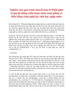
BSE image in Fig. 4 shows infiltrated slag as a bright network between
grains, covering almost the entire material. The sample exposed for
27 h was oriented with the left side in the figure towards the reactor
center, a large crack going from the upside and down into the material
is visible on the probes outer edge filled with slag, denoted by a red
arrow.
Table 2
Measured process temperatures by the thermocouples (average ± standard deviation).
Gas temperatures (°C)
T1
T2
T3
T4
1246
1276
1268
1219
±
±
±
±
27
19
20
20
T9
T10
T11
T12
Probe T1
Probe T2
T5
T6
T7
T8
Table 3
Resulting dry syngas composition during gasification (average ± standard deviation).
Refractory temperatures (°C)
643 ± 35
968 ± 20
1005 ± 16
1088 ± 29
927 ± 43
1077 ± 81
1170
1114
1087
1045
±
±
±
±
18
20
20
22
T13
T14
T15
T16
1125 ± 22
1095 ± 22
1055 ± 21
933 ± 16
4
Gas species
Concentration in dry syngas (mol-%)
H2
N2
CH4
CO
CO2
C2H2
C2H4
C2H6
13.6 ± 1.9
35.6 ± 4.0
0.2 ± 0.1
23.7 ± 4.0
23.6 ± 3.3
< 0.01
< 0.01
< 0.01
Journal of the European Ceramic Society xxx (xxxx) xxx–xxx
M. Carlborg et al.
Table 4
Material specifications for the tested samples.
Refractory material
Composition (wt-%)
Description according to material
specification
High alumina with Ca aluminates (HA + CA)
Al2O3 94%
CaO 4.5%
SiO2 0.1%
Fe2O3 0.05%
Tabular alumina based castable, resistant
against abrasion, dust erosion or impact at
high temperatures.
Andalusite (ADL)
Al2O3 62%
SiO2 33%
CaO 1.4%
TiO2 1.4%
Fe2O3 1.1%
Andalusite based, strong castable with high
shock resistance.
High alumina spinel fused casted (HASPf1)
Al2O3 64%
MgO 35%
Other 1%
Void free fused cast refractory (spinel > 90%;
periclase < 10%)
High alumina spinel fused casted (HASPf2)
Al2O3 53.6%
MgO 44.9%
Other 1%
Magnesia rich fused cast refractory.
Silicon carbide low cement (SCLC)
SiC 60%
Al2O3 30%
SiO2 5%
Fe2O3 0.2%
Low cement castable base on silicon carbide
with good thermal conductivity and high
abrasion, oxidation and thermal shock
resistance.
Hibonite (HB)
Al2O3 90.6%
CaO 8.5%
SiO2 0.8%
Fe2O3 0.1%
Hibonite-based castable for high-alkali
refractory applications
Isopressing zirconia with mullite (ZR + ML)
Al2O3 66%
ZrO2 20%
SiO2 12%
Acidic refractory with low thermal expansion
coefficient, resistant to slags in glass,
chemical and metallurgic industries.
Graphite Brick (C)
Graphite
–
3.1.3. High alumina spinel fused casted (HASPf1)
For 6 and 27 h, slag had penetrated the material to a depth of about
40 μm. slag was found in some larger cavities connected to the surface.
After exposure, the crystalline phase leucite could be found in addition
to the original phases (periclase and spinel). In Fig. 4 an overview
image is displayed, no slag intrusion is visible on this scale. Slag intrusion via pores was not as extensive in this material as in the other
fused cast material.
3.1.2. Andalusite (ADL)
Slag infiltration is visible as loss of porosity and up to 2 at.-% K in
the refractory matrix. After 6, and 27 h of exposure the matrix was
severely affected to depths of about 0.7 and 3 mm, respectively but
partial intrusion could be observed through the whole samples. In addition to the original phases (andalusite, corundum and mullite), the
new phases anorthite and leucite could be detected. In Fig. 5 the interface between slag and refractory is displayed where slag has infiltrated the matrix and crystals (likely anorthite) have formed on the
surface. The matrix had a similar appearance further into the material
but with more porosity preserved. An overview of the material exposed
for 27 h is displayed in Fig. 4.
3.1.4. High alumina spinel fused casted (HASPf2)
In addition to infiltration via large pores (displayed in Fig. 4 and
indicated by a red arrow), the dense parts of the fused cast spinel was
infiltrated to a depth of about 30 μm. In Fig. 6 a BSE image with
Fig. 2. Water cooled sample probe with mounted refractory sample (top probe). Thermocouple (type-S) position is shown in the picture (bottom probe).
5
Journal of the European Ceramic Society xxx (xxxx) xxx–xxx
M. Carlborg et al.
surface is displayed in Fig. 8. The slag has a darker shade than the
refractory parts in these images because the refractory has a higher
average elemental composition. Two small peaks of what seems to be
mullite could be seen in the XRD pattern for the unexposed material.
These peaks were weakened in the exposed material and no phase could
be assigned with certainty. These findings indicate that the binding
mullite phase is being dissolved by the slag with loosening of grains on
the surface as a result.
3.2. Thermodynamic equilibrium calculations
The slag composition from the graphite probe was assumed to be the
true composition of the ash slag, due to the lack of components in this
probe that could be dissolved by the slag. A temperature of 1220 °C was
used in all calculations based on the shielded thermocouple TC-4 that
was located at approximately the same level as the exposed material
probes. A gasification atmosphere corresponding to the measured gas
composition was also fixed. Under these conditions, the slag is predicted to be completely molten within a two-phase melt.
Phase assemblages were generated based on the bulk compositions
of each refractory material and the slag. The major (and minor) phases
predicted are listed in Table 7. They are mostly in agreement with the
phases identified from XRD but differences are expected given the
heterogeneous make-up of the refractories, phase formation kinetics
and transport limitations. For example, the lack of anorthite formation
in the HB-brick indicates that factors besides thermodynamics have an
influence over the slag refractory interactions. Leucite was also not
predicted for slag interactions with MgO nor spinel. Instead olivine and
sapphirine, respectively, were the main phases predicted.
Phase assemblages were also generated to evaluate the stability of
the 12 crystalline phases identified in the pristine refractories.
Anorthite was predicted to be formed as a major crystalline phase from
slag interactions with CaAl2O4, corundum, diaoyudaoite, grossite, andalusite, mullite, hibonite and, to a much lesser extent, spinel. This is in
agreement with the anorthite phase found from the HA + CA, ADL and
SCLC refractories. A solid solution of melilite was also predicted to form
from slag interactions with CaAl2O4 and grossite, which was identified
in the HA + CA-brick. The formation of these phases, in particular
melilite and anorthite may cause degradation, due to changes in density
upon their formation (Table 6). Not only is the density lowered, but
material is also added. This will cause a material expansion followed by
stress and possibly crack formation.
Given that the matrix of refractories often interact more extensively
with the slag and facilitate penetration, TECs and viscosity estimations
were carried out using the matrix compositions. These were based on
the step-wise calculation method introduced by Reinmöller et al. [19].
Initially, a TEC of 100 g of the original slag composition and 100 g
refractory matrix was carried out. The resulting molten slag composition was then normalized to 100 g, and together with 120 g of refractory, the equilibrium was then calculated again. This procedure was
repeated with the amount of refractory matrix increasing by 20 g increments until a final molten slag to refractory matrix ratio of at least
3.8 g/g (i.e. 15 calculations). The phases predicted are demonstrated
for the HA + CA and HASPf2 matrices in Fig. 9.
Estimations of the molten slag viscosities for each calculation were
carried out with the Viscosity module in FactSage 7 and are shown in
Fig. 10.
The ADL, SCLC and ZR + ML matrices produce very viscous melts
with increasing refractory matrix, suggesting that slag penetration
would be limited. On the other hand, the HB matrix interacts with the
slag to become more fluid with increasing matrix share in equilibrium
with anorthite, corundum and hibonite. The fluidity of the melt and the
formation of anorthite are possible reasons as to why this refractory
probe did not last as long as the others. The HA + CA matrix also forms
a very fluid melt, in equilibrium with mainly hibonite, in addition to
smaller amounts of anorthite and melilite.
Fig. 3. Photo taken from the top of the gasifier showing the refractory samples installed
in the reactor. Note that the graphite sample was removed before this photo was taken,
thereof the empty position in the top of the image.
Table 5
Elemental composition of fuel ash and average slag composition on all probes, slag on
graphite probe, average of slag on spinel materials presented on an carbon and oxygen
free basis in at.-%.
a
Fuel ash composition
Slag averageb
Slag on graphite probec
Slag on spinel materialb
a
b
c
Na
Mg
Al
Si
P
K
Ca
Fe
1.4
1.9
2.4
1.9
6.1
6.1
4.6
9.5
11.0
16.3
9.9
15.8
32.3
43.0
54.8
39.5
3.9
2.8
1.9
3.0
8.6
7.6
6.9
7.4
24.0
17.5
13.4
18.1
12.7
4.9
5.6
4.9
Calculated from major element composition.
Obtained from EDS-analyses.
Obtained from ICP-analyses, taken as true slag composition.
elemental maps for Mg, Al, and Si quantified on a carbon and oxygen
free basis is shown. In the BSE image, slag is the brightest, periclase the
darkest and spinel intermediate shade of gray. After 27 h it could be
observed how some spinel grains had been completely surrounded by
slag.
Slag infiltration in what seems to be MgO positions were observed to
a depth of about 40 μm after 6 h of exposure. Leucite was found after
6 h of exposure and after 27 h, the solid solution augite was detected.
3.1.5. Silicon carbide low cement (SCLC)
After 6 h of exposure the slag had penetrated about 0.9 mm into the
matrix, and 1.4 mm after 27 h, large grains did not appear to have been
attacked by slag. A sharp transition could be observed between infiltrated and unaffected matrix, displayed in Fig. 7. Anorthite had been
formed after exposure.
3.1.6. Hibonite (HB)
After 6 h of exposure slag had penetrated about 2.1 mm into the
refractory. No new crystalline phases could be detected with XRD in
this sample. After 12 h the slag had penetrated about 7 mm into the
material. The intruded slag is visible as bright areas between grains in
Fig. 4 and unaffected areas below are darker. Spinel could be detected
in addition to the original phases (hibonite and corundum).
3.1.7. Isopressing zirconia with mullite (ZR ± ML)
Slag penetration was visible as filled voids between the zircon grains
and was observed 2.5 mm, and about 3.5 mm into the material for
probes exposed 6 h and 27 h, respectively. Dislodged grains could be
seen at the edges of the material, more pronounced for the material that
had been exposed for 27 h. Grains at the edge of the material was also
observed to being disintegrated into smaller, more Zr rich grains. No
new phases could be detected with XRD. An overview of the exposed
materials is displayed in Fig. 4 and a detailed image of the material
6
Journal of the European Ceramic Society xxx (xxxx) xxx–xxx
M. Carlborg et al.
Fig. 4. SEM overview images made with back scattered electron detector of material samples made at 20 kV electron acceleration voltage. Difference in atomic number gives contrast in
these images, and the slag appears brighter due to its heavier average elemental composition except for ZR + ML where the slag is lighter. The top of the sample images have been
oriented upwards in the reactor, and all have the same scale, except HA + CA 27 h, which is at 75% relative the others, 5000 μm scale bar shown. Red bars denote slag infiltration depth,
and approximate limit for severe slag infiltration in the ADL material. The red arrow indicate a large crack in the HA + CA material and a pore filled with slag in the HASPf2 material.
(For interpretation of the references to colour in this figure legend, the reader is referred to the web version of this article.)
Although the HASPf1 and HASPf2 refractories result in very low
viscosity melts, they become compatible with spinel and MgO with
increasing amounts of refractory. This suggests that they will flow and
fill voids, but will not dissolve components of the refractory extensively.
3.3. Potential crystalline phases
The results from XRD analysis are summarized in Table 7 together
with predicted phases from TEC.
3.4. Discussion
When ash slag comes in contact with the material probes, refractory
components dissolve and change the slag composition. Depending on
the dissolved components the slag viscosity, and therefore the continued rate of infiltration, may increase or decrease. In the case of silicon carbide castable and andalusite castable, where Si is abundant, the
viscosity of intruded slag increases as more refractory components are
incorporated and practically comes to a halt. Protection of silicon carbide grains is likely to be acting in a similar way, as the oxygen activity
Fig. 5. SEM image of interface between slag and ADL refractory.
7
Journal of the European Ceramic Society xxx (xxxx) xxx–xxx
M. Carlborg et al.
Fig. 6. Interface between slag and fused cast spinel (HASPf2). Back scattered electron image and concentration maps for Mg, Al, and Si on carbon and oxygen free basis, EDS data was
collected at 10 kV acceleration voltage. The horizontal field of view is 115 μm. Periclase grains are embedded in a spinel matrix. The slag is visible as a brighter shade and it has
penetrated the refractory to a depth of about 40 μm in what appears to be former MgO positions in the refractory.
in the gasifier is high enough to oxidize the carbide, a layer of protective oxide is formed [24]. Removal or fluxing of this layer would
lead to increased wear of the grain. When the castables are mainly
composed of corundum or hibonite, the viscosity of the slag does not
increase and therefore the infiltration is deeper in these materials. Because of the fine microstructure and the intimately mixing of slag and
matrix it is hard to isolate intruded slag when performing elemental
analysis in SEM. Intruded slag could, however, be detected by small
changes in composition of the matrix and changes in microstructure.
The bending of the corundum castable (HA + CA) could be explained
by matrix dissolution that has gone so far that the bulk material loses its
rigidity and bends under gravity. The large cracks in the upper part,
filled with slag, speak for this explanation. An alternative scenario that
could bend the material would be if a large portion of new crystalline
phases is formed on top of the material while the bottom expands less,
with a downward bend as effect.
As the binding phase in the zircon brick (ZR + ML) is being dissolved the slag viscosity is initially increased but as more original slag is
incorporated in this mixture the viscosity is approaching that of unaltered slag. When the binder phase is replaced with slag the zircon
grains becomes mobile. Some grains are seen in the slag after 6 h of
exposure and the effect is more distinct after 27 h. This effect should be
seen for all materials where the matrix is being dissolved by intruded
slag. Higher Si content and larger grains should delay the effect because
Fig. 7. SEM image of ADL material. Slag and refractory interface with infiltrated matrix.
In the lower part the matrix is unaffected by slag.
Fig. 8. Surface of the zircon mullite refractory with dislodged and dissociating grains in
the slag.
8
Journal of the European Ceramic Society xxx (xxxx) xxx–xxx
M. Carlborg et al.
more slag is required to reach viscosities where grains start to move and
the liquid zone must stretch deeper into the material to completely
surround large grains. The small grains at the surface shows higher
concentration of Zr than the large grains but also some Si, Ca, and other
elements found in the slag. This observed disintegration is in contradiction with the TEC predictions. Pure zircon dissociates into oxides at
1673 ± 10 °C [25] but in the presence of impurities it has been observed at far lower temperatures [25–27].
The shape, size and orientation of the slag areas just beneath the
surface of the fused cast spinel-periclase displayed in Fig. 6 are similar
to the periclase areas within the material. Periclase that is not completely embedded in spinel has been dissolved and slag has taken its
place in the material. After 27 h, in addition to the dissolved periclase,
it could be observed how spinel grains were completely surrounded by
slag. This means that even these dense materials are risking to be disassembled from long time exposure in a similar way as the other materials. Even though slag infiltrates and to some extent dissolves it, this
material seems to be the least affected among the tested materials.
The formation of anorthite was predicted from TECs and also observed in Al-silicates and the corundum material. Zhang et al. [28]
found anorthite after exposing alumina to a model slag rich in Ca, Si,
Table 6
Density of minerals identified in pristine and exposed refractories.
Mineral
Density [g/cm3]
Andalusite
Anorthite
CaAl2O4
Corundum
Grossite
Hibonite
Leucite
Melilite
Mullite
Periclase
Quartz
Spinel
Zircon
Zirconia
3.13–3.21
2.74–2.76
2.94
3.98–4.1
2.88
3.83–3.85
2.45–2.5
2.9–3.0
3.11–3.26
3.55–3.57
2.65–2.66
3.6–4.1
4.6–4.7
5.6–6
ZrSiO4 was predicted to be stable against the slag, while ZrO2
would lead to the formation of ZrSiO4.
Table 7
Identified crystalline phases in samples.
Refractory
Unexposed material
6h
27 h
TEC phase assemblage
High alumina with Ca
aluminates (HA + CA)
CaAl2O4
Al2O3 (corundum)
CaAl2Si2O8 (anorthite)
CaAl2Si2O8 (anorthite)
Al2O3 (corundum)
NaAl11O17
(diaoyudaoite)
CaAl4O7 (grossite)
NaAl11O17 (diaoyudaoite)
Ca2Al2SiO7 (gehlenite)
Al2O3 (corundum)
Ca2Al2SiO7 (gehlenite)
Ca,Mg-Aluminate
Corundum
MgAl2O4 (spinel)
MgAl2O4 (spinel)
CaAl12O19 (hibonite)
(Spinel)
(Leucite)
Andalusite (ADL)
Al2SiO5 (andalusite)
Al2O3 (corundum)
Al6Si2O13 (mullite)
Al2SiO5 (andalusite)
CaAl2Si2O8 (anorthite)
Al2O3 (corundum)
Al2SiO5 (andalusite)
CaAl2SiO8 (anorthite)
Al2O3 (corundum)
CaAl2Si2O8 (anorthite)
Mullite
(Cordierite)
(Tridymite)
High alumina spinel fused
casted (HASPf1)
MgO (periclase)
KAlSi2O6 (leucite)
KAlSi2O6 (leucite)
Sapphirine (Mg4Al10Si2O23)
MgAl2O4 (spinel)
MgO (periclase)
MgAl2O4 (spinel)
MgO (periclase)
MgAl2O4 (spinel)
Spinel
Monoxide
Olivine
MgO (periclase)
KAlSi2O6 (leucite)
Sapphirine (Mg4Al10Si2O23)
MgAl2O4 (spinel)
MgO (periclase)
MgAl2O4 (spinel)
(Ca, Na)(Mg, Fe, Al, Ti)(Si, Al)2O6
(augite, solid solution)
KAlSi2O6 (leucite)
MgO (periclase)
MgAl2O4 (spinel)
Al2O3 (corundum)
CaAl2Si2O8 (anorthite)
CaAl2Si2O8 (anorthite)
CaAl2Si2O8 (anorthite)
SiO2 (quartz,
cristobalite)
SiC (different types)
Al2O3 (corundum)
Al2O3 (corundum)
Cordierite
SiC
SiO2 (quartz)
SiC
Mullite
Tridymite
Hibonite (HB)a
Al2O3 (corundum)
CaAl12O19 (hibonite)
Al2O3 (corundum)
CaAl12O19 (hibonite)
Al2O3 (corundum)
CaAl12O19 (hibonite)
MgAl2O4 (spinel)
CaAl2Si2O8 (anorthite)
Corundum
Hibonite
Ca,Mg-Aluminate
(Spinel)
(Leucite)
Isopressing Zirconia with
mullite (ZR + ML)
Al6Si2O13 (mullite)
ZrSiO4 (zircon)
ZrSiO4 (zircon)
CaAl2Si2O8 (anorthite)
ZrSiO4 (zircon)
ZrO2 (zirconia)
ZrO2 (zirconia)
ZrO2 (zirconia)
Corundum
ZrSiO4 (zircon)
ZrO2 (zirconia)
Mullite (Sapphirine)
High alumina spinel fused
casted (HASPf2)
Silicon carbide low cement
(SCLC)
Graphite Brick (C)
a
C (graphite)
SiO2 (Cristobalite, quartz)
The would-be 27 h sample broke and fell out of the gasification chamber after approximately 12 h.
9
Spinel
Monoxide
Olivine
Journal of the European Ceramic Society xxx (xxxx) xxx–xxx
M. Carlborg et al.
Fig. 9. Phase distribution for slag/refractory matrix interaction (left) HA + CA and (right) HASPf2.
Fig. 10. Viscosity estimation of melts penetrating refractories.
also spinel was dissolved from the fused cast spinel. Castables with high
Si content showed less intrusion than those with low Si content. This is
attributed to the altered slag composition followed by changes in
viscosity. The zircon brick showed signs of failure by dissolution of the
binding mullite phase which led to removal of zircon grains from the
material surface. These grains also dissociated which was in contradiction with the TECs. Anorthite was formed in the corundum castable,
mullite castable, and SiC-corundum casTable Spinel was the only new
phase detected in the hibonite castable even though TECs predicted
mainly anorthite and Ca-Mg-aluminate, with only minor levels of
spinel.
and Fe at a temperature of 1600 °C. Ptáček et al. [29] studied formation
of gehlenite, Al-Si spinel, and anorthite from heating kaolinite and
calcite. Upon heating of this mixture gehlenite was formed at temperatures above 950 °C and anorthite at 1256 °C. Schaafhausen et al.
[30] found gehlenite after exposing mullite to wood ash (mainly Ca and
K, with ∼8% Si, and < 2% Al) at 950 °C and 800 °C. During formation
of these phases, besides that more mass in form of CaO is added to the
system, the density of the products are lower than the ones in the original refractory which means that the volume will increase. Formation
of hibonite was not seen in this study even though it was predicted by
TECs for some materials. Other researchers have observed hibonite
formation from corundum in contact with Ca- rich slag [19,28,31,32]
and also from letting natural dolomite decompose and react with corundum [33]. These experiments were however done with temperatures
above 1500 °C as compared to about 1220 °C in this study.
The severity of the mentioned destructive effects (swelling, spalling,
dissolution and dislodging of grains) taking place in refractories should
be ranked and assessed when choosing a material. Even though one
refractory might not be thermodynamically stable, it may be resilient
enough to have an acceptable time of service.
Acknowledgments
This work has been founded by the Swedish Energy Agency through
Bio4Gasification, which is highly acknowledged by the authors of this
work. Calle Yllipää, Henry Hedman, Jonas Wennebro, Yngve Ögren,
Esbjörn Pettersson and Mattias Lundgren are also highly acknowledged
for invaluable assistance before, during and after the experiments. Bo
Heidenfors at Fagersta Eldfasta is also gratefully acknowledged for
supply and helpful advice regarding materials to be tested. Prof. Marcus
Öhman is also thanked for his insightful comments and critique to
improve this manuscript.
4. Conclusions
All tested materials showed signs of wear after 6 and 27 h exposure
but fused cast spinel seemed least affected in terms of slag intrusion and
formation of new phases. The slag on refractory probes all had higher Al
concentrations than ash slag collected on a graphite probe, which
means that Al is being dissolved from all materials. Mainly periclase but
References
[1] C. Higman, M. van der Burgt, Gasification, GPP, 2008, 2017.
[2] F. Weiland, H. Hedman, M. Marklund, H. Wiinikka, O. Öhrman, R. Gebart,
10
Journal of the European Ceramic Society xxx (xxxx) xxx–xxx
M. Carlborg et al.
[3]
[4]
[5]
[6]
[7]
[8]
[9]
[10]
[11]
[12]
[13]
[14]
[15]
[16]
[17]
Pressurized oxygen blown entrained-flow gasification of wood powder, Energy
Fuels 27 (2) (2013) 932–941.
F. Weiland, H. Wiinikka, H. Hedman, J. Wennebro, E. Pettersson, R. Gebart,
Influence of process parameters on the performance of an oxygen blown entrained
flow biomass gasifier, Fuel 153 (2015) 510–519.
K. Kwong, A. Petty, J. Bennett, R. Krabbe, H. Thomas, Wear mechanisms of chromia
refractories in slagging gasifiers, Int. J. Appl. Ceram. Technol. 4 (6) (2007)
503–513.
H. Kim, M. Oh, Changes in microstructure of a high chromia refractory du to interaction with infiltrating coal slag in a slagging gasifier environment, Ceram. Int.
34 (8) (2008) 2107–2116.
E. Medvedovski, R. Chinn, Corrosion resistant refractory ceramics for slagging gasifier environment, Ceram. Eng. Sci. Proc. 25 (3) (2004) 547–552.
P. Gehre, C. Aneziris, M. Klinger, M. Schreiner, M. Neuroth, Influence of TiO2- and
ZrO2-addition on the interaction of alumina castable with molten coal and gasifier
slag, Fuel 150 (2015) 252–260.
R.-S. Xu, X.-C. Lin, Y.-G. Wang, Morphological and interfacial characterization of
molten slag on the refractory surface, J. Fuel Chem. Technol. 43 (2) (2015)
138–144.
J. Nakano, S. Sridhar, J. Bennett, K.-S. Kwong, T. Moss, Interactions of refractory
materials with molten gasifier slags, Int. J. Hydrogen Energy 36 (7) (2011)
4595–4604.
S. Vassilev, C. Vassileva, V. Vassilev, Advantages and disadvantages of composition
and properties of biomass in comparison with coal: An overview, Fuel 158 (2015)
330–350.
G. Zhang, M. Reinmöller, M. Klinger, B. Meyer, Ash melting behavior and slag infiltration into alumina refractory simulating co-gasification of coal and biomass,
Fuel 139 (2015) 457–465.
V. Krishnamoorthy, S. Pisupati, A critical review of mineral matter related issues
during gasification of coal in fixed, fluidized, and entrained flow gasifiers, Energies
8 (2015) 10430–10463.
P. Carlsson, C. Ma, R. Molinder, F. Weiland, H. Wiinikka, M. Öhman, O. Öhrman,
Slag formation during oxygen-blown entrained-flow gasification of stem wood,
Energy Fuels 28 (11) (2014) 6941–6952.
M. Rådberg, Black Liquor Gasification – Experimental Stability Studies of Smelt
Components and Refractory Lining, Umeå University, Umeå, 2007.
J. Simonsson, H. Bladh, M. Gullberg, E. Pettersson, A. Sepman, Y. Ögren,
H. Wiinikka, P.-E. Bengtsson, Soot concentrations in an atmospheric entrained flow
gasifier with variations in fuel and burner configuration studied using diode-laser
extinction measurements, Energy Fuels 30 (2016) 2174–2186.
C. Ma, M. Carlborg, H. Hedman, J. Wennebro, F. Weiland, H. Wiinikka,
R. Backman, M. Öhman, Ash formation in pilot-scale pressurized entrained-flow
gasification of bark and a bark/peat mixture, Energy Fuels 30 (12) (2016)
10543–10554.
C. Bale, E. Bélisle, P. Chartrand, S. Decterov, G. Eriksson, A. Gheribi, K. Hack, L.H. Jung, Y.-B. Kang, J. Melacon, A. Pelton, S. Petersen, E. Robelin, J. Sangster,
P. Spencer, M.-A. Van Ende, FactSage thermochemical software and databases,
[18]
[19]
[20]
[21]
[22]
[23]
[24]
[25]
[26]
[27]
[28]
[29]
[30]
[31]
[32]
[33]
11
2010–2016, Calphad: Comput. Coupl. Phase Diagr. Thermochem. 54 (35-53) (2016)
2016.
K. Hack, S. Petersen, P. Koukkari, K. Penttilä, CHEMSHEET – an efficient worksheet
tool for thermodynamic process simulation, in: Y. Bréchet (Ed.), Microstructures,
Mechanical Properties and Processes – Computer Simulation and Modelling,
EUROMAT 99, Volume 3 Wiley-VCH Verlag GmbH, Weinheim, 2000, pp. 323–330.
M. Reinmöller, M. Klinger, E. Thieme, B. Meyer, Analysis and prediction of slaginduced corrosion of chromium oxide-free refractory material during fusion of coal
and biomass ash under simulated gasification conditions, Fuel Process. Technol.
149 (2016) 218–230.
J. Keiser, J. Hemrick, J. Gorog, R. Leary, Improved Materials for High-Temperature
Black Liquor Gasification, United States, Department of Energy, Office of Energy
Efficiency and Renewable Energy, Oak Ridge, 2006.
J. Bennett, K. Kwong, Failure mechanisms in high chrome oxide gasifier refractories, Metallurg. Mater. Trans. A-Phys. Metall. Mater. Sci. 42A (4) (2011)
888–904.
J. Bennett, K. Kwong, Refractory liner materials used in slagging gasifiers, Refract.
Appl. News 9 (5) (2004) 20–25.
A. Malfliet, S. Lotfian, L. Scheunis, V. Petkov, L. Pandelaers, P. Jones, B. Blanpain,
Degradation mechanisms and use of refractory linings in copper production processes: a critical review, J. Eur. Ceram. Soc. 34 (3) (2014) 849–876.
E. Gulbransen, S. Jansson, High-temperature oxidation, reduction, and volatilization reactions of silicon and silicon-carbide, Oxid. Met. 4 (3) (1972) 181–201.
A. Kaiser, M. Lobert, R. Telle, Thermal stability of zircon (ZrSiO4), J. Eur. Ceram.
Soc. 28 (11) (2008) 2199–2211.
T. Váczi, L. Nasdala, R. Wirth, M. Mehofer, E. Libowitzky, T. Hager, On the
breakdown of zircon upon "dry" thermal annealing, Mineral. Petrol. 97 (1-2) (2009)
129–138.
P. Peña, S. de Aza, The zircon thermal-behavior – effect of impurities, J. Mater. Sci.
19 (1) (1984) 135–142.
S. Zhang, H. Rezaie, H. Sarpoolaky, W. Lee, Alumina dissolution into silicate slag, J.
Am. Ceram. Soc. 83 (4) (2000) 897–903.
P. Ptáček, F. Šouka, T. Opravil, M. Nosková, J. Havlica, The kinetics of Al–Si spinel
phase crystallization from calcined kaolin, J. Solid State Chem. 183 (11) (2010)
2565–2569.
S. Schaafhausen, E. Yazhenskikh, A. Walch, S. Heidenreich, M. Mueller, Corrosion
of alumina and mullite hot gas filter candles in gasification environment, J. Eur.
Ceram. Soc. 33 (15-16) (2013) 3301–3312.
B. Vazquez, P. Pena, A. de Aza, M. Sainz, A. Caballero, Corrosion mechanism of
polycrystalline corundum and calcium hexaluminate by calcium silicate slags, J.
Eur. Ceram. Soc. 29 (8) (2009) 1347–1360.
P. Gehre, C. Aneziris, H. Berek, C. Parr, M. Reinmöller, Corrosion of magnesium
aluminate spinel-rich refractories by sulphur-containing slag, J. Eur. Ceram. Soc. 35
(5) (2015) 1613–1620.
A. de Aza, P. Pena, J. Moya, Reactive coating of dolomite on alumina substrates, J.
Eur. Ceram. Soc. 17 (7) (1997) 935–941.