Model driven engineering for distributed real time embedded systems
Bạn đang xem bản rút gọn của tài liệu. Xem và tải ngay bản đầy đủ của tài liệu tại đây (8.31 MB, 250 trang )
Model-Driven Engineering
for Distributed Real-Time Systems
www.it-ebooks.info
www.it-ebooks.info
Model-Driven Engineering
for Distributed
Real-Time Systems
MARTE Modeling, Model Transformations
and their Usages
Edited by
Jean-Philippe Babau
Mireille Blay-Fornarino
Joël Champeau
Sylvain Robert
Antonio Sabetta
www.it-ebooks.info
First published 2010 in Great Britain and the United States by ISTE Ltd and John Wiley & Sons, Inc.
Apart from any fair dealing for the purposes of research or private study, or criticism or review, as
permitted under the Copyright, Designs and Patents Act 1988, this publication may only be reproduced,
stored or transmitted, in any form or by any means, with the prior permission in writing of the publishers,
or in the case of reprographic reproduction in accordance with the terms and licenses issued by the
CLA. Enquiries concerning reproduction outside these terms should be sent to the publishers at the
undermentioned address:
ISTE Ltd
27-37 St George’s Road
London SW19 4EU
UK
John Wiley & Sons, Inc.
111 River Street
Hoboken, NJ 07030
USA
www.iste.co.uk
www.wiley.com
© ISTE Ltd 2010
The rights of Jean-Philippe Babau, Mireille Blay-Fornarino, Joël Champeau, Sylvain Robert and Antonio
Sabetta to be identified as the authors of this work have been asserted by them in accordance with the
Copyright, Designs and Patents Act 1988.
Library of Congress Cataloging-in-Publication Data
Model-driven engineering for distributed real-time systems : MARTE modeling, model transformations,
and their usages / edited by Jean-Philippe Babau ... [et al.].
p. cm.
Includes bibliographical references and index.
ISBN 978-1-84821-115-5
1. Model-driven software architecture. 2. Electronic data processing--Distributed processing. 3. Realtime data processing. 4. UML (Computer science). I. Babau, Jean-Philippe.
QA76.76.D47M622 2010
005.2'732--dc22
2010027955
British Library Cataloguing-in-Publication Data
A CIP record for this book is available from the British Library
ISBN 978-1-84821-115-5
Printed and bound in Great Britain by CPI Antony Rowe, Chippenham and Eastbourne.
www.it-ebooks.info
Table of Contents
Chapter Summary . . . . . . . . . . . . . . . . . . . . . . .
xi
Chapter 1. Model Transformation: A Survey
of the State of the Art . . . . . . . . . . . . . . . . . . . . .
1
Tom MENS
1.1. Model-driven engineering . . . . . .
1.2. Model transformation . . . . . . . .
1.2.1. Definitions . . . . . . . . . . . . . .
1.2.2. Taxonomy . . . . . . . . . . . . . .
1.3. Model transformation languages .
1.4. Model transformation activities .
1.5. Conclusion . . . . . . . . . . . . . . . .
1.6. Acknowledgements . . . . . . . . . .
1.7. Bibliography . . . . . . . . . . . . . . .
.
.
.
.
.
.
.
.
.
.
.
.
.
.
.
.
.
.
.
.
.
.
.
.
.
.
.
.
.
.
.
.
.
.
.
.
.
.
.
.
.
.
.
.
.
.
.
.
.
.
.
.
.
.
.
.
.
.
.
.
.
.
.
.
.
.
.
.
.
.
.
.
.
.
.
.
.
.
.
.
.
.
.
.
.
.
.
.
.
.
.
.
.
.
.
.
.
.
.
1
2
2
4
5
8
14
14
15
Chapter 2. Model-Based Code Generation . . . . .
21
Chris RAISTRICK
2.1. Introduction . . . . . . . . . . . . . . . . . . . . . . . .
2.2. The model-driven architecture (MDA) process
2.3. The automated approach to code generation . .
2.4. Domain modeling . . . . . . . . . . . . . . . . . . . .
2.5. The executable UML (xUML) formalism . . . .
2.6. System generation . . . . . . . . . . . . . . . . . . . .
www.it-ebooks.info
.
.
.
.
.
.
.
.
.
.
.
.
21
22
23
25
29
31
vi
Model-Driven Engineering
2.7. Executable UML to code mappings . . . . . . . . . .
2.8. Conclusions . . . . . . . . . . . . . . . . . . . . . . . . . .
2.9. Bibliography . . . . . . . . . . . . . . . . . . . . . . . . . .
34
41
42
Chapter 3. Testing Model Transformations:
A Case for Test Generation from Input Domain
Models . . . . . . . . . . . . . . . . . . . . . . . . . . . . . . . .
43
Benoit BAUDRY
3.1. Introduction . . . . . . . . . . . . . . . . . . . . . . . . . .
3.2. Challenges for testing systems with large input
domains . . . . . . . . . . . . . . . . . . . . . . . . . . . . . . . .
3.2.1. Large set of input data . . . . . . . . . . . . . . . .
3.2.2. Configurable systems . . . . . . . . . . . . . . . . .
3.2.3. Grammarware and model transformations . .
3.2.4. Testing challenges . . . . . . . . . . . . . . . . . . .
3.3. Selecting test data in large domains . . . . . . . . .
3.3.1. Category partition . . . . . . . . . . . . . . . . . . .
3.3.2. Combinatorial interaction testing . . . . . . . .
3.4. Metamodel-based test input generation . . . . . . .
3.4.1. Metamodel coverage criteria . . . . . . . . . . . .
3.4.2. Model and object fragments for test
adequacy criteria . . . . . . . . . . . . . . . . . . . . . . . .
3.4.3. Discussion . . . . . . . . . . . . . . . . . . . . . . . . .
3.4.4. Automatic synthesis of test models . . . . . . .
3.5. Conclusion . . . . . . . . . . . . . . . . . . . . . . . . . . .
3.6. Acknowledgements . . . . . . . . . . . . . . . . . . . . .
3.7. Bibliography . . . . . . . . . . . . . . . . . . . . . . . . . .
Chapter 4. Symbolic Execution-Based
Techniques for Conformance Testing . . . . . . . .
43
46
46
48
48
52
52
52
55
58
59
61
64
65
67
68
68
73
Christophe GASTON, Pascale LE GALL, Nicolas RAPIN and Assia
TOUIL
4.1. Context . . . . . . . . . . . . . . . . . . . . . . . .
4.1.1. Conformance testing: an introduction
4.1.2. Conformance relation . . . . . . . . . . . .
4.1.3. An overview of the approach . . . . . . .
www.it-ebooks.info
.
.
.
.
.
.
.
.
.
.
.
.
.
.
.
.
.
.
.
.
73
73
74
78
Table of Contents
4.2. Input output symbolic transition systems . . .
4.2.1. Data types . . . . . . . . . . . . . . . . . . . . . . .
4.2.2. Input/output symbolic transition systems .
4.2.3. Semantics . . . . . . . . . . . . . . . . . . . . . . .
4.3. Symbolic execution . . . . . . . . . . . . . . . . . . .
4.4. Conformance testing for IOSTS . . . . . . . . . .
4.4.1. Test purposes . . . . . . . . . . . . . . . . . . . . .
4.4.2. Preliminary definitions and informal
description . . . . . . . . . . . . . . . . . . . . . . . . . . .
4.4.3. Inference rules . . . . . . . . . . . . . . . . . . . .
4.5. Concluding remarks . . . . . . . . . . . . . . . . . .
4.5.1. Choosing test purposes . . . . . . . . . . . . . .
4.5.2. Implementation issues . . . . . . . . . . . . . .
4.6. Bibliography . . . . . . . . . . . . . . . . . . . . . . . .
vii
.
.
.
.
.
.
.
.
.
.
.
.
.
.
79
79
80
82
84
87
88
.
.
.
.
.
.
. 89
. 94
. 96
. 96
. 101
. 101
Chapter 5. Using MARTE and SysML for
Modeling Real-Time Embedded Systems . . . . . . 105
Huascar ESPINOZA, Daniela CANCILA,
Sébastien GÉRARD and Bran SELIC
5.1. Introduction . . . . . . . . . . . . . . . . . . . . . . . .
5.2. Background . . . . . . . . . . . . . . . . . . . . . . . .
5.2.1. UML profiling capabilities . . . . . . . . . . . .
5.2.2. SysML and MARTE modeling capabilities
5.3. Scenarios of combined usage . . . . . . . . . . . . .
5.3.1. Defining architecture frameworks . . . . . .
5.3.2. Requirements engineering. . . . . . . . . . . .
5.3.3. System-level design integration . . . . . . . .
5.3.4. Engineering/quantitative analysis . . . . . .
5.4. Combination Strategies . . . . . . . . . . . . . . . .
5.4.1. Issues . . . . . . . . . . . . . . . . . . . . . . . . . .
5.4.2. Strategies . . . . . . . . . . . . . . . . . . . . . . .
5.5. Related work. . . . . . . . . . . . . . . . . . . . . . . .
5.6. Conclusion . . . . . . . . . . . . . . . . . . . . . . . . .
5.7. Acknowledgements . . . . . . . . . . . . . . . . . . .
5.8. Bibliography . . . . . . . . . . . . . . . . . . . . . . . .
www.it-ebooks.info
.
.
.
.
.
.
.
.
.
.
.
.
.
.
.
.
.
.
.
.
.
.
.
.
.
.
.
.
.
.
.
.
105
108
108
111
113
114
115
117
120
125
125
128
130
133
134
134
viii
Model-Driven Engineering
Chapter 6. Software Model-based Performance
Analysis . . . . . . . . . . . . . . . . . . . . . . . . . . . . . . .
139
Dorina C. PETRIU
6.1. Introduction . . . . . . . . . . . . . . . . . . . . . . . . .
6.2. Performance models . . . . . . . . . . . . . . . . . . .
6.2.1. Queuing network models . . . . . . . . . . . . .
6.2.2. Layered queuing network model . . . . . . . .
6.3. Software model with performance annotations .
6.3.1. Performance domain model . . . . . . . . . . . .
6.3.2. Source model example . . . . . . . . . . . . . . .
6.4. Mapping from software to performance model .
6.5. Using a pivot language: Core Scenario
Model (CSM) . . . . . . . . . . . . . . . . . . . . . . . . . . .
6.6. Case study performance model . . . . . . . . . . . .
6.7. Conclusions . . . . . . . . . . . . . . . . . . . . . . . . .
6.8. Acknowledgements . . . . . . . . . . . . . . . . . . . .
6.9. Bibliography . . . . . . . . . . . . . . . . . . . . . . . . .
.
.
.
.
.
.
.
.
139
142
144
146
148
148
152
155
.
.
.
.
.
158
160
162
163
163
Chapter 7. Model Integration for Formal
Qualification of Timing-Aware Software Data
Acquisition Components . . . . . . . . . . . . . . . . . .
167
Jean-Philippe BABAU, Philippe DHAUSSY and
Pierre-Yves PILLAIN
7.1. Introduction . . . . . . . . . . . . . . .
7.2. System modeling. . . . . . . . . . . .
7.2.1. Acquisition system modeling .
7.2.2. Case study . . . . . . . . . . . . .
7.2.3. Formal modeling techniques .
7.3. Variation points modeling . . . . .
7.3.1. Variation points definition . .
7.3.2. CDL implementation . . . . . .
7.4. Experiments and results . . . . . .
7.4.1. Tools. . . . . . . . . . . . . . . . . .
7.4.2. Experimentations . . . . . . . .
www.it-ebooks.info
.
.
.
.
.
.
.
.
.
.
.
.
.
.
.
.
.
.
.
.
.
.
.
.
.
.
.
.
.
.
.
.
.
.
.
.
.
.
.
.
.
.
.
.
.
.
.
.
.
.
.
.
.
.
.
.
.
.
.
.
.
.
.
.
.
.
.
.
.
.
.
.
.
.
.
.
.
.
.
.
.
.
.
.
.
.
.
.
.
.
.
.
.
.
.
.
.
.
.
.
.
.
.
.
.
.
.
.
.
.
.
.
.
.
.
.
.
.
.
.
.
167
170
170
172
174
182
184
187
189
189
191
Table of Contents
ix
7.5. Conclusion . . . . . . . . . . . . . . . . . . . . . . . . . . . 194
7.6. Bibliography . . . . . . . . . . . . . . . . . . . . . . . . . . 195
Chapter 8. SoC/SoPC Development using MDD
and MARTE Profile . . . . . . . . . . . . . . . . . . . . . . 201
Denis AULAGNIER, Ali KOUDRI, Stéphane LECOMTE, Philippe
SOULARD, Joël CHAMPEAU, Jorgiano VIDAL,
Gilles PERROUIN and Pierre LERAY
8.1. Introduction . . . . . . . . . . . . . . . . . . . . . . . . . .
8.2. Related works . . . . . . . . . . . . . . . . . . . . . . . . .
8.3. MOPCOM process and models . . . . . . . . . . . . .
8.4. Application . . . . . . . . . . . . . . . . . . . . . . . . . . .
8.5. System analysis . . . . . . . . . . . . . . . . . . . . . . .
8.5.1. Requirement analysis . . . . . . . . . . . . . . . . .
8.5.2. Functional analysis . . . . . . . . . . . . . . . . . .
8.5.3. Action language . . . . . . . . . . . . . . . . . . . . .
8.6. Abstract modeling level . . . . . . . . . . . . . . . . . .
8.7. Execution modeling level . . . . . . . . . . . . . . . . .
8.7.1. The platform independent model/application
model in EML . . . . . . . . . . . . . . . . . . . . . . . . . . .
8.7.2. The platform model in EML . . . . . . . . . . . .
8.7.3. The platform specific model/allocation model
in EML . . . . . . . . . . . . . . . . . . . . . . . . . . . . . . .
8.7.4. Analysis model . . . . . . . . . . . . . . . . . . . . . .
8.8. Detailed modeling level . . . . . . . . . . . . . . . . . .
8.8.1. Platform model . . . . . . . . . . . . . . . . . . . . .
8.8.2. Allocation model . . . . . . . . . . . . . . . . . . . . .
8.9. Tooling Support . . . . . . . . . . . . . . . . . . . . . . .
8.9.1. Process validation through metamodeling
with Kermeta . . . . . . . . . . . . . . . . . . . . . . . . . . .
8.9.2. Model transformation and generation with
MDWorkbench platform . . . . . . . . . . . . . . . . . . .
8.10. HDL Code Generation . . . . . . . . . . . . . . . . . .
8.10.1. VHDL code generation . . . . . . . . . . . . . . .
8.10.2. Rhapsody integration . . . . . . . . . . . . . . . .
8.11. Conclusion . . . . . . . . . . . . . . . . . . . . . . . . . .
www.it-ebooks.info
201
203
206
210
211
211
212
213
214
216
217
217
218
219
220
221
222
223
223
224
225
226
227
228
x
Model-Driven Engineering
8.12. Acknowledgements . . . . . . . . . . . . . . . . . . . .
8.13. Bibliography . . . . . . . . . . . . . . . . . . . . . . . . .
229
229
List of Authors . . . . . . . . . . . . . . . . . . . . . . . . . .
233
Index . . . . . . . . . . . . . . . . . . . . . . . . . . . . . . . . .
237
www.it-ebooks.info
Chapter Summary
Chapter 1
Model-driven engineering (MDE) is an approach to
software development where the primary focus is on models,
as opposed to source code. The use of models opens up new
possibilities for creating, analyzing, manipulating and
formally reasoning about systems at a high level of
abstraction.
To reap all the benefits of MDE, it is essential to install a
model transformation mechanism, that enables a wide range
of different automated activities such as translation of
models (expressed in different modeling languages),
generating code from models, model synthesis, model
improvement, model verification and model simulation. To
achieve this, languages, formalisms, techniques, processes,
tools and standards that support model transformation are
needed. This chapter surveys the state of the art of model
transformation, and discusses how it can be used to support
some essential activities in MDE.
Chapter 2
This chapter explains how the combination of the OMG’s
Model-Driven architecture (MDA) process and the executable
www.it-ebooks.info
xii
Model-Driven Engineering
UML formalism can be used to specify and build embedded
software systems. It will deal specifically with:
− the Model-Driven Architecture principle of partitioning
a system into domains for which we construct Platform
Independent Models (PIMs);
− the use of Executable UML (xUML) for the construction
of precise, complete PIMs that can be demonstrated and
verified prior to implementation;
− automatic translation of the PIMs into Platform Specific
Models (PSMs) and then into performance compliant code
running on an embedded target.
Chapter 3
Model transformations can automate critical tasks in
model-driven development. Thorough validation techniques
are required to ensure their correctness. In this chapter we
focus on testing model transformations. In particular, we
present an approach for the systematic selection of input test
data. This approach is based on a key characteristic of model
transformations: their input domain is formally captured in
a metamodel. A major challenge for test generation is that
metamodels usually model an infinite set of possible input
models for the transformation.
We start with a general motivation of the need for specific
test selection techniques in the presence of very large and
possibly infinite input domains. We also present two existing
black-box strategies to systematically select test data:
category-partition and combinatorial interaction testing.
Then, we detail specific criteria based on metamodel
coverage to select data for model transformation testing. We
introduce object and model fragments to capture specific
structural constraints that should be satisfied by input test
data. These fragments are the basis for the definition of
www.it-ebooks.info
Chapter Summary
xiii
coverage criteria and for the automatic generation of test
data. They also serve to drive the automatic generation of
models for testing.
Chapter 4
In this chapter we discuss techniques to test whether a
system conforms to its model given in terms of an
Input/Output Symbolic Transition System (IOSTS). IOSTSs
are automata-based models using data types to enrich
transitions with data-based messages and guards depending
on state variables. We focus on symbolic execution
techniques both to extract IOSTS behaviors to be tested in
the role of test purposes and to ground test case generation.
Chapter 5
Using model-based approaches for designing embedded
systems helps remove unnecessary details in a manner that
reduces production costs, increases the potential for easy
validation and verification, and facilitates reuse and
evolution. In this context, a common practice is to use UML
as the base language, possibly specialized by the so-called
profiles. Despite the ever increasing number of profiles being
built in many domains, there is still insufficient focus on
discussing the issue of combining multiple profiles. Indeed, a
single profile may not be adequate to cover all aspects
required in the multidisciplinary domain of embedded
systems.
In this chapter, we assess possible strategies for
combining the SysML and MARTE profiles in a common
modeling framework, while avoiding specification conflicts.
We show that, despite some semantic and syntactical
overlapping, the two are highly complementary for specifying
embedded systems at different abstraction levels. We
www.it-ebooks.info
xiv
Model-Driven Engineering
conclude, however, that a convergence agenda is highly
desirable to ensure proper alignment of some key language
features.
Chapter 6
This chapter starts with a brief review of performance
modeling formalisms and a discussion of the performance
annotations that need to be added to UML software models
in order to enable performance analysis. The principles for
transforming annotated software models into performance
models are then presented. Such model transformations
must bridge a large semantic gap between the source and the
target model; hence a pivot model is often used. An example
of such a transformation is given, from UML extended with
the MARTE profile to the Layered Queueing Network
performance model. The role of an intermediate pivot
language called Core Scenario Model is also discussed. The
chapter ends with a discussion of the lessons learned and
future challenges for integrating the analysis of multiple
non-functional properties in the context of MDE.
Chapter 7
This chapter proposes to integrate design and formal
modeling approaches, based on MARTE, IF and CDL, to
evaluate different possible uses and configurations of a data
acquisition software component. The uses are related to the
actor’s (sensor and application) behavior and configurations
are related to implementation parameterization. Evaluation
considers safety and performance properties and delay
evaluation, which are automatically evaluated by the OBP
tool. The work is illustrated using an example to show the
impact of parameters and contextual use on software
acquisition driver performances. Using this tool, it is possible
to tune the driver’s parameters to obtain the required
www.it-ebooks.info
Chapter Summary
xv
performances, in terms of delays, for a certain context use.
The approach is applied to sensor monitoring applications.
Chapter 8
This chapter presents a new methodology for developing
SoC/SoPC applications. This methodology is based on UML
and MDD and capitalizes on the achievements of the
“Electronic System Level” community by taking into account
the new MARTE profile dedicated to real-time embedded
systems. In the MOPCOM SoC/SoPC research project, a
tooling has been developed to support this SoC/SoPC
methodology, the MARTE profile, HDL code generation and
documentation generation. A Cognitive Radio demonstrator
is presented to illustrate the methodology and the tooling.
www.it-ebooks.info
Chapter 1
Model Transformation:
A Survey of the State of the Art
Rien ne se perd, rien ne se crée, tout se transforme.
(Nothing is lost, nothing is created, everything is transformed)
Antoine-Laurent de Lavoisier (1743-1794)
1.1. Model-driven engineering
Model-Driven Engineering (MDE) is an approach to
software development where the principle artefacts are
models (as opposed to source code). It is a natural next step
in the evolution of software development to continue to raise
the level of abstraction in order to tackle increasingly
complex problems. The main goal is to reduce the accidental
complexity [BRO 86] of software, caused by the technology,
methods and programming languages used to develop
software. Of course, the essential complexity that is inherent
to the problem to be solved cannot be reduced, no matter
which approach, technology or language is adopted.
Chapter written by Tom MENS.
Model-Driven Engineering for Distributed Real-Time Systems: MARTE Modeling, Model Transformations and their Usages
Edited by Jean-Philippe Babau, Mireille Blay-Fornarino, Joël Champeau, Sylvain Robert and Antonio Sabetta
© 2010 ISTE Ltd. Published 2010 by ISTE Ltd.
www.it-ebooks.info
2
Model-Driven Engineering
The basic principle behind MDE is that everything is a
model. As such, it provides a generic approach to deal with
all possible software artefacts used and produced during
the software development life-cycle (e.g. requirement
specifications, analysis and design documents, test suites,
source code, and so on). Even the languages used to specify
the models can be considered as models too, which are
referred to as metamodels.
The current state-of-the-practice of tool support for MDE is
still in the round-trip engineering stage: the models and the
code co-exist, and a change to either of the two artefacts
requires a synchronization of the other. Ideally, this
synchronization is automated, but in practice there is often
some manual effort involved as well. In contrast, the state of
the art in MDE support is model centric, where the code can
be fully generated from the models [RAI 04].
Accepting the basic idea that everything is a model, and
adopting a model-centric view, we need techniques and tools
that allow us to manipulate and reason about such models.
The technique that can be used to achieve this is commonly
referred to as model transformation. According to [SEN 03,
GER 02], model transformation is the heart and soul of
model-driven software development. It is needed for
supporting a wide range of model-driven activities such as
code generation, model extraction, model refactoring, model
verification, model simulation, and many more.
1.2. Model transformation
1.2.1. Definitions
Kleppe et al. [KLE 03] provide the following definition of
model transformation: a transformation is the automatic
generation of a target model from a source model, according
to a transformation definition. A transformation
www.it-ebooks.info
Model Transformation
3
definition is a set of transformation rules that together
describe how a model in the source language can be
transformed into a model in the target language. A
transformation rule is a description of how one or more
constructs in the source language can be transformed into one
or more constructs in the target language.
This definition is very general, and covers a wide range of
activities for which model transformation can be used:
automatic code generation, model synthesis, model evolution,
model simulation, model execution, model quality
improvement (e.g. through model refactoring), model
translation, model-based testing, model checking, model
verification, and many more. For some types of activities we
would like to support, the definition needs to be extended, in
order to allow for model transformations that take more than
one source model as input and/or produce multiple target
models as output. The different source (resp. target) models
do not even need to be described in the same modeling
language. Examples of activities where we need more than
one source or target model are model merging (in the context
of collaborative modeling), model weaving and model
composition [FLE 07, HID 09].
In order to support this variety of model transformation
activities, we need to put in place a number of different
mechanisms. Obviously, we need transformation languages
that describe how to specify model transformations. This will
be the topic of section 1.3. For those languages that have an
underlying formal foundation, we need formal methods and
theories to rely on. We also need tools that implement and
support these languages and formalisms. A wide variety of
such tools is available, research prototypes as well as
commercial tools. Methodologies or processes are needed in
order to help us to use all of these mechanisms in an efficient
way. Examples are the Rational Unified Process (RUP, [KRU
03]) and the Executable UML methodology based on the
www.it-ebooks.info
4
Model-Driven Engineering
Schlaer-Mellor method [RAI 04]. To facilitate communication
and interoperability, standards are needed for all of the
above. The most obvious standards are those proposed by the
OMG (e.g. UML, XMI, QVT, MOF, OCL, SysML and many
more). Other de facto “standards” are those proposed by the
Eclipse community (e.g. EMF, ECore, and so on).
1.2.2. Taxonomy
[MEN 06c] proposed a taxonomy of model transformation.
Many of the ideas in this taxonomy were based on the
discussions of a working group of a 2004 Dagstuhl seminar
on Language Engineering for Model-Driven Software
Development. We briefly review the essential parts of this
taxonomy here.
Endogenous versus exogenous transformations
In order to transform models, these models need to be
expressed in some modeling language (e.g. UML). A
distinction can be made between endogenous and exogenous
transformations, depending on the language(s) used to
express source and target models involved in the model
transformation.
Endogenous
transformations
are
transformations between models expressed in the same
language. Exogenous transformations are transformations
between models expressed using different languages.
A typical example of an exogenous model transformation
is model synthesis, in which a design model is extracted from
source code. The inverse exogenous transformation is code
generation to transform the design models into source code.
Another well-known example of exogenous model
transformation is model translation, in order to transform
some representation of a model into an equivalent
representation expressed in a different modeling language
(e.g. UML to XMI, or class diagrams to entity-relationship
diagrams).
www.it-ebooks.info
Model Transformation
5
A typical example of endogenous transformation is
optimization: it aims to improve certain operational qualities
(e.g. performance), while preserving the semantics of the
model. A related endogenous transformation is model
refactoring, which aims to improve the model structure.
Horizontal versus vertical transformations
An orthogonal way to classify model transformation is by
looking at the abstraction level of its source and target
models. For horizontal transformations, the source and
target models must reside at the same level of abstraction.
Typical examples are model refactoring (an endogenous
transformation) and model translation (an exogenous
transformation). For vertical transformations, the source and
target models must reside at different abstraction levels. A
typical example is refinement, where a specification is
gradually refined into a full-fledged implementation, by
means of successive refinement steps that add more concrete
details [BAC 98].
1.3. Model transformation languages
Model transformation languages serve to specify the
syntax and semantics of model transformations, and are
essential if we want to provide automated support for model
transformation. A wide variety of model transformation
languages exist. Many of them have emerged from the
academic community, while others originate from industry.
In the latter category we find, for example, OMG’s QVT
specification [OBJ 08], which is compatible with the MDA
approach based on MOF and UML. The academic languages
include, without attempting to be complete: ATL, Kermeta,
Tefkat, SiTra and many languages that are based on the
underlying approach of graph transformation (e.g. ATOM3,
AGG, Fujaba, GReAT, MOFLON, VIATRA2).
www.it-ebooks.info
6
Model-Driven Engineering
Due to this wealth of transformation languages, it is
necessary to provide a taxonomy that allows us to assess the
conceptual commonalities and differences between these
languages. This is the purpose of the current section.
Declarative versus operational
A first criterion to compare transformation languages is
whether they rely on a declarative or an operational (a.k.a.
imperative or constructive) specification.
Declarative approaches focus on what needs to be
transformed into what by defining a relationship or mapping
between the source and target models. These approaches are
attractive because they tend to be easier to write and
understand by software engineers. In addition, desirable
services such as source model traversal, traceability
management and bidirectional transformations may be
offered by the underlying transformation engine.
Operational approaches focus on how the transformation
needs to be performed by specifying the steps that are
required to derive the target models from the source models.
Such approaches may be required to implement
transformations for which declarative approaches fail to
guarantee their services. Especially when the application
order of a set of transformations needs to be controlled
explicitly, an imperative approach is more appropriate
thanks to its built-in notions of sequence, selection and
iteration. Such explicit control may be required to implement
transformations that reconcile source and target models
after they have been both heavily manipulated outside the
transformation tool.
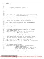
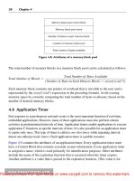
Interestingly, the QVT specification [OBJ 08] offers two
different languages: QVT Relational is a declarative
transformation language, while QVT Operational belongs to
the category of operational languages. Figure 1.1 shows an
www.it-ebooks.info
Model Transformation
7
example of the use of QVT Relational, while Figure 1.2
shows an example expressed in QVT Operational.
Figure 1.1. Part of the Class2RDBMS model
transformation expressed using QVT Relational
transformation UML2RDBMS (in uml:UML, out rdbms:RDBMS) {
// content of the transformation definition }
mapping Class:class2table() : Table when
{self.isPersistent()}
{ name := 't_' + self.name;
column := self.attribute->map attr2column();
key := self.map class2key(result.column);
}
mapping Attribute:attr2column() : Column
{ name := self.name;
type := getSqlType(self.type);
}
mapping Class:class2key(in cols:Sequence(Column)) : Key
{ name := 'k_' + self.name;
column := cols[kind='primary'];
}
Figure 1.2. Part of the Class2RDBMS model
transformation expressed using QVT Operational
Textual versus visual
Another criterion to distinguish model transformation
languages is how their concrete syntax is specified. Textual
transformation languages (such as ATL and Kermeta)
www.it-ebooks.info
8
Model-Driven Engineering
require us to specify the model transformations using a
textual description. Visual transformation languages (such
as nearly all of the graph transformation languages) specify
model transformations in a visual way.
Note that some transformation languages offer both
alternatives. For example, for QVT Relational [OBJ 08], both
a visual and a textual syntax is available. The visual syntax
is illustrated in Figure 1.1, whereas the textual syntax is
illustrated in Figure 1.2.
Other distinguishing characteristics
Many other criteria can be used to compare or distinguish
model transformation languages. For example, we can
distinguish between general-purpose and domain-specific
transformation languages. We can also distinguish between
languages that have been designed and implemented in an
ad hoc way as opposed to languages that have a formal
underlying foundation. As we will see later, the latter type of
languages can be exploited to achieve some kind of formal
analysis of the model transformations they represent.
Finally, the expressiveness of the transformation language
is also very important. Ideally, the language should provide
mechanisms to facilitate (de)composition and reuse of model
transformations, the ability to specify higher-order
transformations (transformations that can transform
transformations), the ability to specify bidirectional
transformations (a possibility that is offered by triple graph
grammar approaches [GIE 06] such as MOFLON1, and so
on).
1.4. Model transformation activities
In this section, we will provide a brief overview, with
references to relevant literature, of a wide variety of model1. .
www.it-ebooks.info
Model Transformation
9
based activities in which model transformations are
essential. While this overview is inevitably incomplete, it
allows us to illustrate the importance and breadth of the
field of model transformation.
Automatic code generation
Undoubtedly, code generation is one of the main
motivations for using model transformation technology. It is
used by various companies, including Airbus [SAB 09].
According to OMG’s MDA approach [KLE 03], the goal is to
transform platform-independent models (PIMs) into
platform-specific models (PSMs) and ultimately to source
code generated from these models. According to our
transformation taxonomy in section 1.2.2, code generation is
an example of a vertical, exogenous transformation.
Ideally, this type of transformation should be as
automated as possible. Seen in this light, a promising
approach is Executable UML [RAI 04]. It uses an action
semantics language integrated into a well-defined subset of
the UML to allow full code generation from models.
Model extraction
Model extraction is another example of a vertical,
exogenous transformation. It is the inverse of code
generation, and is an essential activity in reverse
engineering and program comprehension. Taking the source
code as input, it allows us to build a mental or visual model
(e.g. a UML model) at a higher level of abstraction, in order
to facilitate understanding of the code and how it is
structured [MUR 01].
Model translation
Model translation is one of the horizontal, exogenous
types of model transformation that has been used frequently
in research literature for different purposes. In general, the
goal is to transform a model, expressed in a particular
www.it-ebooks.info
10
Model-Driven Engineering
modeling language, into an “equivalent” model in another
modeling language. A typical example of such a model
transformation, that has been used frequently in research
literature is the Class2RDBMS model transformation (see,
e.g. [WIM 07, HID 09]). Its aim is to convert a class model
(e.g. a UML class diagram) into a relational database model.
This transformation is sometimes referred to as the objectrelational mapping. It provides a bridge between the world of
object-oriented specifications and relational database
specifications. A partial example of this transformation,
expressed using QVT, has been presented in Figures 1.1 and
1.2.
Another important application of model translation is to
cope with the ill-defined, underspecified, semantics of some
modeling languages (such as UML) by translating them into
another semantic domain that has a sound formal semantics,
so that we can apply some form of formal analysis to our
models. [ANA 07] attempted to transform UML models into
the formal language Alloy, and encountered several problems
in doing so. [VAN 03] proposed a translation of UML models
into the description logics formalism. [HER 08] translated
UML class and sequence diagrams into the domain of graph
transformation, thereby giving an operational and
denotational semantics to a subset of UML.
A third reason for using model translation is to facilitate
interoperability. We sometimes wish to use and interchange
models between different modeling tools, and even between
different modeling languages. A typical example is the
translation of some tool-specific representations of UML
models into XMI (and vice versa), OMG’s XML-based
standard for model interchange [OBJ 07]. This facilitates
exchanging UML models between different UML modeling
tools.
www.it-ebooks.info