Shop manua máy đào KOMATSU PW75R-2
Bạn đang xem bản rút gọn của tài liệu. Xem và tải ngay bản đầy đủ của tài liệu tại đây (13.25 MB, 464 trang )
CONTENTS
00-1
PW75R-2
No. of page
10 STRUCTURE AND FUNCTION .............................................
10-1
20 TESTING AND ADJUSTING ................................................
20-1
30 DISASSEMBLY AND ASSEMBLY...........................................
30-1
40 MAINTENANCE STANDARD ...............................................
40-1
00-2
PW75R-2
Pages having no marks are those previously revised
or made additions.
00-2-1
PW75R-2
Mark Indication Action required
C Page to be newly
Add
c Page to be replaced
Replace
( ) Page to be delete
Discard
LIST OF REVISED PAGES
The affected pages are indicated by the use of the
following marks. It is requested that necessary ac-
tions be taken to these pages according to table
Mark Page
Time of
revision
Mark Page
Time of
revision
Mark Page
Time of
revision
Mark Page
Time of
revision
Mark Page
Time of
revision
00-1
00-2
00-2-1
00-2-2
00-3
00-4
00-5
00-6
00-7
00-8
00-9
00-10
00-11
00-12
00-13
00-14
10-1
10-2
10-3
10-4
10-5
10-6
10-7
10-8
10-9
10-10
10-11
10-12
10-13
10-14
10-15
10-16
10-17
10-18
10-19
10-20
10-21
10-22
10-23
10-24
10-25
10-26
10-27
10-28
10-29
10-30
10-31
10-32
10-33
10-34
10-35
10-36
10-37
10-38
10-39
10-40
10-41
10-42
10-43
10-44
10-45
10-46
10-47
10-48
10-49
10-50
10-51
10-52
10-53
10-54
10-55
10-56
10-57
10-58
10-59
10-60
10-61
10-62
10-63
10-64
10-65
10-66
10-67
10-68
10-69
10-70
10-71
10-72
10-73
10-74
10-75
10-76
10-77
10-78
10-79
10-80
10-81
10-82
10-83
10-84
10-85
10-86
10-87
10-88
10-89
10-90
10-91
10-92
10-93
10-94
10-95
10-96
10-97
10-98
10-99
10-100
10-101
10-102
10-103
10-104
10-105
10-106
10-107
10-108
10-109
10-110
10-111
10-112
10-113
10-114
10-115
10-116
10-117
10-118
10-119
10-120
10-121
10-122
10-123
10-124
10-125
10-126
10-127
10-128
10-129
10-130
10-131
10-132
10-133
10-134
10-135
10-136
10-137
10-138
10-139
10-140
10-141
10-142
10-143
10-144
10-145
10-146
10-147
20-1
20-2
20-3
20-4
20-5
20-6
20-7
20-8
20-9
20-10
20-11
20-12
20-13
20-14
20-15
20-16
20-17
20-18
20-19
20-20
20-21
20-22
20-23
20-24
20-25
20-26
20-27
20-28
20-29
20-30
20-31
20-32
20-33
20-34
20-35
20-36
20-37
20-38
20-39
20-40
20-41
00-2-2
PW75R-2
Mark Page
Time of
revision
Mark Page
Time of
revision
Mark Page
Time of
revision
Mark Page
Time of
revision
Mark Page
Time of
revision
20-42
20-43
20-44
20-45
20-46
20-47
20-48
20-49
20-50
20-51
20-52
20-53
20-54
20-55
20-56
20-57
20-58
20-59
20-60
20-61
20-62
20-63
20-64
20-65
20-66
20-67
20-68
20-69
20-70
20-71
20-72
20-73
20-74
20-75
20-76
30-1
30-2
30-3
30-4
30-5
30-6
30-7
30-8
30-9
30-10
30-11
30-12
30-13
30-14
30-15
30-16
30-17
30-18
30-19
30-20
30-21
30-22
30-23
30-24
30-25
30-26
30-27
30-28
30-29
30-30
30-31
30-32
30-33
30-34
30-35
30-36
30-37
30-38
30-39
30-40
30-41
30-42
30-43
30-44
30-45
30-46
30-47
30-48
30-49
30-50
30-51
30-52
30-53
30-54
30-55
30-56
30-57
30-58
30-59
30-60
30-61
30-62
30-63
30-64
30-65
30-66
30-67
30-68
30-69
30-70
30-71
30-72
30-73
30-74
30-75
30-76
30-77
30-78
30-79
30-80
30-81
30-82
30-83
30-84
30-85
30-86
30-87
30-88
30-89
30-90
30-91
30-92
30-93
30-94
30-95
30-96
30-97
30-98
30-99
30-100
30-101
30-102
30-103
30-104
30-105
30-106
30-107
30-108
30-109
30-110
30-111
30-112
30-113
30-114
30-115
30-116
30-117
30-118
30-119
30-120
30-121
30-122
30-123
30-124
30-125
30-126
30-127
30-128
30-129
30-130
30-131
30-132
30-133
30-134
30-135
30-136
30-137
30-138
30-139
30-140
30-141
30-142
30-143
30-144
30-145
30-146
30-147
30-148
30-149
30-150
30-151
30-152
30-153
30-154
30-155
30-156
30-157
30-158
30-159
30-160
30-161
30-162
30-163
30-164
30-165
30-166
30-167
30-168
30-169
30-170
40-1
40-2
40-3
40-4
40-5
40-6
40-7
40-8
40-9
40-10
40-11
40-12
40-13
40-14
40-15
40-16
40-17
40-18
40-19
40-20
40-21
40-22
40-23
40-24
40-25
40-26
40-27
40-28
40-29
40-30
40-31
40-32
40-33
40-34
40-35
40-36
40-37
40-38
40-39
40-40
40-41
40-42
40-43
40-44
40-45
40-46
40-47
40-48
40-49
40-50
40-51
40-52
GENERAL PRECAUTIONS
Mistakes in operation extremely dangerous.
Read all the Operation and Maintenance Manual care-
fully BEFORE operating the machine.
1. Before carrying out any greasing or repairs, read
all the precautions written on the decals which
are suck on the machine.
2. When carrying out any operation, always wear sa-
fety shoes and helmet. Do not wear loose work
clothes, or clothes with buttons missing.
. Always wear safety glasses when hitting parts
with a hammer.
. Always wear safety glasses when grinding
parts with a grinder, etc.
3. If welding repairs are needed, always have a trai-
ned, experienced welder carry out the work.
When carrying out welding work, always wear
welding gloves, apron, glasses, cap and other clo-
thes suited for welding work.
4. When carrying out any operation with two or more
workers, always agree on the operating procedure
before starting. Always inform your fellow workers
before starting any step of the operation. Before
starting work, hang UNDER REPAIR signs on
the controls in the operator's compartment.
5. Keep all tools in good condition and learn the cor-
rect way to use them.
6. Decide a place in the repair workshop to keep
tools and removed parts. Always keep the tools
and parts in their correct places. Always keep
the work area clean and make sure that there is
no dirt or oil on the floor.
Smoke only in the areas provided for smoking.
Never smoke while working.
PREPARATIONS FOR WORK
7. Before adding or making any repairs, park the ma-
chine on hard, level ground, and block the wheels
to prevent the machine from moving.
8. Before starting work, lower outrigger, bucket or
any other work equipment to the ground. If this
is not possible, use blocks to prevent the work
equipment from falling down. In addition, be sure
to lock all the control levers and hang warning
sign on them.
9. When disassembling or assembling, support the
machine with blocks, jacks or stands before star-
ting work.
10. Remove all mud and oil from the steps or other
places used to get on and off the machine. Always
use the handrails, ladders or steps when getting
on or off the machine.
Never jump on or off the machine.
If it is impossible to use the handrails, ladders or
steps, use a stand to provide safe footing.
PRECAUTIONS DURING WORK
11. When removing the oil filler cap, drain plug or hy-
draulic pressure measuring plugs, loosen them
slowly to prevent the oil from spurting out.
Before disconnecting or removing components of
the hydraulic circuit and engine cooling circuit,
first remove the pressure completely from the cir-
cuit.
12. The water and oil in the circuits are not hot when
the engine in stopped, so be careful not to get
burned.
Wait for the oil water to cool before carrying out
any work on the cooling water circuits.
00-3
PW75R-2
IMPORTANT SAFETY NOTICE
Proper service and repair is extremely important for the safe operation of your machine.
The service and repair techniques recommended by FKI and describe in this manual are both effective
and safe methods of operation. Some of these operations require the use of tools specially designed by
FKI for the purpose.
To prevent injury to workers, the symbols
and are used to mark safety precautions in this ma-
nual. The cautions accompanying these symbols should always be carefully followed. If any danger ari-
ses or may possibly arise, first consider safety, and take necessary steps to face.
SAFETY
13. Before starting work, remove the leads from the
battery. Always remove the lead from the negative
( ± ) terminal first.
14. When raising heavy components, use a hoist or
crane. Check that the wire rope, chains and hooks
are free from damage.
Always use lifting equipment which has ample ca-
pacity. Install the lifting equipment at the correct
places.
Use a hoist or crane and operate slowly to prevent
the component from hitting any other part.
Do not work with any part still raised by the hoist
or crane.
15. When removing covers which are under internal
pressure or under pressure from a spring, always
leave two bolts in position on opposite sides.
Slowly release the pressure, then slowly loosen
the bolts to remove.
16. When removing components, be careful not to
break or damage the wiring.
Damage wiring may cause electrical fires.
17. When removing piping, stop the fuel or oil from
spilling out. If any fuel or oil drips on to the floor,
wipe it up immediately.
Fuel or oil on the floor can cause you to slip, or
can even start fires.
18. As a general rule, do not use gasoline to wash
parts. In particular, use only the minimum of gaso-
line when washing electrical parts.
19. Be sure to assemble all parts again in their origi-
nal places. Replace any damage parts with new
parts.
. When installing hoses and wires, be sure that
they will not be damaged by contact with other
parts when the machine is being operated.
20. When installing high pressure hoses, make sure
that they are not twisted. Damaged tubes are dan-
gerous, so be extremely careful when installing
tubes for high pressure circuits. Also, check that
connecting parts are correctly tightened.
21. When assembling or installing parts, always use
specified tightening torques.
When installing the parts which vibrate violently or
rotate at high speed, be particulary careful to
check that they are correctly installed.
22. When aligning two holes, never insert your fingers
or hand.
23. When measuring hydraulic pressure, check that
the measuring tool is correctly assembled before
taking any measurement.
24. Take sure when removing or installing tracks of in
particular rubber tracks. When removing the
track, the track separates suddenly, so never let
anyone stand at either end of the wheel.
00-4
PW75R-2
00-5
PW75R-2
FOREWORD
This shop manual has been prepared as an aid to improve the quality of repairs by giving the operator an ac-
curate understanding of the product and by showing him the correct way to perform repairs and make judgements.
Make sure you understand the contents of this manual and use it to full effect at every opportunity.
This shop manual mainly contains the necessary technical information for operations performed in a service
workshop.
The manual is divided into chapters on each main group of components; these chapters are further divided into
the following sections.
STRUCTURE AND FUNCTION
This section explains the structure and function of each component. It serves not only to give an understan-
ding of the structure, but also serves as reference material for troubleshooting.
TESTING AND ADJUSTING
This sections explains checks to be made before and after performing repairs, as well as adjustments to be
made at completion of the checks and repairs.
Troubleshooting charts correlating «Problems» to «Causes» are also included in this section.
DISASSEMBLY AND ASSEMBLY
This section explains the order to be followed when removing, installing, disassembling or assembling
each component, as well as precautions to be taken for these operations.
MAINTENANCE STANDARD
This section gives the judgement standards when inspecting disassembled parts.
NOTE
The specifications contained in this shop manual are subject to change at any time and without any
notice.
Contact your FKI distributor for the latest information.
VOLUMES
Shop manual are issued as a guide to carry out re-
pairs. These various volumes are designed to avoid
duplicating the same information.
DISTRIBUTION AND UPDATING
Any additions, amendments or other changes will
be sent to FKI distributors.
Get the most up-to-date information before you start
any work.
FILING METHOD
1. See the page number on the bottom of the page.
File the pages in correct order.
2. Following examples show you how to read the pa-
ge number.
Example
3. Additional pages: additional pages are indicated
by a hyphen (-) and number after the page num-
ber.
Fle as in the example.
Example:
10-4
10-4-1
10-4-2
10-5
]
Added pages
REVISED EDITION MARK
(123....)
When a manual is revised, an edition mark is recor-
ded on the bottom outside corner of the pages.
REVISIONS
Revised pages are shown on the LIST OF REVI-
SED PAGES between the title page and SAFETY pa-
ge.
SYMBOLS
In order to make the shop manual greatly chelpful,
important points about safety and quality are marked
with the following symbols.
Symbol Item Remarks
Safety
Special safety precautions are ne-
cessary when performing the
work.
Extra special safety precautions
are necessary when performing
the work because it is under inter-
nal pressure.
Caution
Special technical precautions or
other precautions for preserving
standards are necessary when
performing the work.
Weight
Weight of parts or systems.
Caution necessary when selecting
hoisting wire, or when working po-
sture is important, etc.
Tightening
torque
Parts that require special attention
for the tightening torque during as-
sembly.
Coat
Parts to be coated with adhesives
and lubricants etc.
Oil, water
Places where oil, water or fuel
must be added, and their quantity.
Drain
Places where oil or water must be
drained, and quantity to be drai-
ned.
HOW TO READ THE SHOP MANUAL
HOW TO READ THE SHOP MANUAL
00-6
PW75R-2
Numero dell'articolo (10. Struttura e
funzionamento)
Numero di pagina progressivo per
ogni articolo
10 - 3
Heavy parts (25 kg or more) must be lifted
with a hoist etc. In the Disassembly and As-
sembly section, every part weighing 25 kg or
more is clearly indicated with the symbol
1. If a part cannot be smoothly removed from the
machine by hoisting, the following checks should
be made:
. Check for removal of all bolts fastening the part
to the relative parts.
. Check for any part causing interference with
the part to be removed.
2. Wire ropes
1) Use adequate ropes depending on the weight
of parts to be hoisted, referring to the table be-
low:
WIRE ROPES
(Standard «S» or «Z» twist ropes
without galvanizing)
Rope diameter (mm) Allowable load (tons)
10
11.2
12.5
14
16
18
20
22.4
30
40
50
60
1.0
1.4
1.6
2.2
2.8
3.6
4.4
5.6
10.0
18.0
28.0
40.0
The allowable load value is estimated to be
one-sixth or one-seventh of the breaking
strength of the rope used.
2) Sling wire ropes from the middle portion of the
hook. Slinging near the edge of the hook may
cause the rope to slip off the hook during hoist-
ing, and a serious accident can result.
Hooks have maximum strength at the middle
portion.
3) Do not sling a heavy load with one rope alone,
but sling with two or more ropes symmetrically
wound on to the load.
Slinging with one rope may cause turning of
the load during hoisting, untwisting of the ro-
pe, or slipping of the rope from its original
winding position on the load, which can cau-
se dangerous accidents.
4) Do not sling a heavy load with ropes forming a
wide hanging angle from the hook.
When hoisting a load with two or more ropes,
the force subjected to each rope will increase
with the hanging angles.
The table below shows the variation of allowa-
ble load (kg) when hoisting is made with two ro-
pes, each of which is allowed to sling up to
1000 kg vertically, at various handing angles.
When two ropes sling a load vertically, up to
2000 kg of total weight can be suspended.
This weight becomes 1000 kg when two ropes
make a 120ë hanging angle.
On the other hand, two ropes are subjected to
an excessive force as large as 4000 kg if they
sling a 2000 kg load at a lifting angle of 150ë.
HOISTING INSTRUCTIONS
HOISTING INSTRUCTIONS
00-7
PW75R-2
STANDARD TIGHTENING TORQUE
STANDARD TIGHTENING TORQUE
00-8
PW75R-2
The following charts give the standard tightening torques of bolts and nuts. Exceptions are given in sections of «Di-
sassembly and Assembly».
1. STANDARD TIGHTENING TORQUE OF BOLTS AND NUT
Thread diameter
of bolts
(mm)
Pitch of
bolts
(mm)
Width across flat
(mm)
kgm Nm kgm Nm
6
8
10
12
14
1
1,25
1,5
1,75
2
10
13
17
19
22
5
6
8
10
12
0,96w0,1
2,3w0,2
4,6w0,5
7,8w0,8
12,5w1
9,5w1
23w2
45w4,9
77w8
122w13
1,3w0,15
3,2w0,3
6,5w0,6
11w1
17,5w2
13,5w1,5
32,2w3,5
63w6,5
108w11
172w18
16
18
20
22
24
2
2,5
2,5
2,5
3
24
27
30
32
36
14
14
17
17
19
19,5w2
27w3
38w4
52w6
66w7
191w21
262w28
372w40
511w57
644w70
27w3
37w4
53w6
73w8
92w10
268w29
366w36
524w57
719w80
905w98
27
30
33
36
39
3
3,5
3,5
4
4
41
46
50
55
60
19
22
24
27
Ð
96w10
131w14
177w20
230w25
295w33
945w100
1287w140
1740w200
2250w250
2900w330
135w15
184w20
250w27
320w35
410w45
1329w140
1810w190
2455w270
3150w350
4050w450
This torque table does not apply to bolts or nuts which have to fasten nylon or other parts non-ferrous metal washer.
. Nm (Newton meter): 1 Nm = 0.102 kgm
STANDARD TIGHTENING TORQUE
00-9
PW75R-2
Superficie di tenuta
Sealing surface
2. TIGHTENING TORQUE FOR NUTS OF FLARED
Use these torques for nut part of flared.
Thread diameter
of nut part
(mm)
Width across flats
of nut part
(mm)
TIGHTENING TORQUE
kgm Nm
1/2" - 20
9/16" - 18
3/4" - 16
7/8" - 14
1.
1
/
16
"
-12
1.
5
/
16
"
-12
1.
5
/
8
"
-12
22
33
17
17
22
27
32
38
50
27
41
2.6w0.5
4w0.5
6.7w2
8w2
9.7w3
17w3
20w5
8w2
20w5
25.5w4.9
39.2w4.9
65.7w19.6
78.5w19.6
95.15w29.4
166.7w29.4
196.2w49
78.5w19.6
196.2w49
Thread diameter
of nut part
(mm)
Width across flats
of nut part
(mm)
TIGHTENING TORQUE
kgm Nm
9/16" - 18
11/16" - 16
13/16" - 16
1" - 14
1.
3
/
16
"
-12
1.
7
/
16
"
-12
1.
11
/
16
"
-12
2" - 12
17
22
24
30
36
41
50
57
2.3 ± 2.5
3.4 ± 3.9
5.2 ± 5.8
8.2 ± 9.2
12.2 ± 13.3
15.3 ± 17.3
18.4 ± 20.4
20.4 ± 24.4
23 ± 25
33 ± 38
51 ± 57
80 ± 90
120 ± 130
150 ± 170
180 ± 200
200 ± 240
00-10
PW75R-2
COATING MATERIALS
The recommended coating materials prescribed in FKI Shop Manuals are listed below:
Nomenclature Code Applications
Adhesives
ASL800010
Used to apply rubber pads, rubber gaskets and cork plugs.
ASL800020
Used to apply resin, rubber, metallic and non-metallic parts when a fast, strong
seal is needed.
Loctite 222
Used for low resistance locking of screws, check nuts and adjustment nuts.
Loctite 242
To prevent the loosening of bolts, nuts and plugs and the leakage of oil. Used for
medium resistance locking of screws and nuts of every type, and for locking keys
and bearings.
Loctite 262
Used for high resistant of threaded parts that can be removed with normal tools.
Loctite 270
Used for high resistant locking and for sealing threaded parts, bolts and stud bolts.
Loctite 542
Used for sealing the union threads for hydraulic tubes.
Loctite 573
Used for sealing rather exact plane surfaces when the option of possible future
dismantling is required.
Loctite 601
Used for high resistant locking of mechanical components that can be removed
only after heating
Loctite 675
Used to lock cylindrical couplings and for the permanent locking of threaded parts,
and also to lock shafts to bearings, gears, pulleys, pins, bushings, etc.
Gasket sealant
ASL800060
Used by itself to seal grease fittings, tapered screw fittings and tapered screw fit-
tings in hydraulic circuits of less than 50 mm in diameter.
Loctite 510
Used by itself on mounting flat surface
(Clearance between surfaces within 0.2 mm)
Loctite 518
Used by itself on mounting flat surface
(Clearance between surfaces within 0.5 mm)
Antifriction compound
(Lubricant including
Molybdenum disulfide)
ASL800040
Applied to bearings and taper shaft to facilitate press-fitting and to prevent stic-
king, burning or rusting.
Grease
(Lithium grease)
ASL800050
Applied to bearings, sliding parts and oil seals for lubrication, rust prevention and
facilitation of assembling work.
Vaseline
±
Used for protecting battery electrode terminals from corrosion.
ELECTRIC WIRE CODE
ELECTRIC WIRE CODE
00-11
PW75R-2
ELECTRIC
In the wiring diagrams various colours and symbols are employed to indicate the thickness of wires.
This wire code table will help you understand WIRING DIAGRAMS.
Example: R -N 1.5 indicates a cable having a nominal number 1.5 and red coating with black stripe.
CLASSIFICATION BY THICKNESS
Nominal
number
Copper wire
Cable O.D.
(mm)
Current rating
(A)
Number
strands
ù of strands
(mm)
Cross section
(mm
2
)
1 14 0.30 0.99 2.80 11
1.5 21 0.30 1.48 3.35 14
2.5 35 0.30 2.47 3.80 20
4 56 0.30 3.95 4.60 28
6 84 0.30 5.93 5.20 37
10 84 0.40 10.55 7.10 53
50 399 0.40 50.11 14 160
CLASSIFICATION BY COLOUR AND CODE
Primary Auxiliary
Code A A-G ± A-N ± A-R ± A±V A/V A±B ±
Colour Light blue Light blue - Yellow Light blue - Black Light blue - Red Light blue - Green Light blue - White
Code B B-G ± B-N ± B-R B/R ±±±±
Colour White White - Yellow White - Black White - Red ± ±
Code C C-V ± C-N C/N C±B C/B C±L ± ± ±
Colour Orange Orange - Green Orange - Black Orange - White Orange - Blue ±
Code G G-R G/R G-N G/N G±V ± G±L ± ± ±
Colour Yellow Yellow - Red Yellow - Black Yellow - Green Yellow - Blue ±
Code H H-R ± H-N ± H±G ± H±L ± ± ±
Colour Gray Gray - Pink Gray - Black Gray - Yellow Gray - Blue ±
Code L L-R L/R L-B ± ± L/G ±±±±
Colour Blue Blue - Red Blue - White Blue - Yellow ± ±
Code M M-N M/N M±V ± M±B ±±±±±
Colour Brown Brown - Black Brown - Green Brown - White ± ±
Code N ±±±±±±±±±±
Colour Black ±±±±±
Code R R-N R/N R-V ± R±G ±±±±±
Colour Red Red - Black Red - Green Red - Yellow ± ±
Code S S-N ± S±G ±±±±±±±
Colour Pink Pink - Black Pink - Yellow ± ± ±
Code V V-B V/B V-N ±±±±±±±
Colour Green Green - White Green - Black ± ± ±
Code Z Z-B Z/B Z-N ±±±±±±±
Colour Violet Violet - White Violet - Black ± ± ±
COMPOSITION OF THE COLOURS
The coloration of two-colour wires is indicated by the composition of the symbols listed.
Example: G-V = Yellow-Green with longitudinal colouring.
G/V = Yellow-Green with transversal colouring.
WEIGHT TABLE
00-12
PW75R-2
This weight table is a guide for use when transporting or handling components.
Unit: kg
Machine model PW75R-2
From serial no. 22E0200001-
Engine assembly 380
Radiator - exchanger 35,5
Hydraulic tank (without hydraulic oil) 60
Fuel tank (without fuel) 40
Counterweight 1050
Swing circle 89
Revolving frame 765
Swing machinery assembly 43
Main hydraulic pump ± Gear pump 57
Cabin 250
Seat 32
Seat support 14,5
Platform 51
Control valve 60
Track frame assembly 640
Front axle 357
Rear axle (2WS) 301
Rear axle (4WS) 378
Wheel 74
Swivel joint 54
Axle locking cylinder 22
Swing bracket 170
Engine hood ±
Front hood ±
Boom 300
1
st
boom 245
2
nd
boom 162
Arm (L=1700) 125
Arm (L=2100) 167
Outrigger 76
Bracket 28
Blade - outrigger support 105
Blade 191
TABLE OF OIL AND COOLANT QUANTITIES
00-13
PW75R-2
RESERVOIR
KIND OF
FLUID
AMBIENT TEMPERATURE CAPACITY (
<
)
±20 ±10 0 10 20 30ëC
Specified Refill
Crankcase sump
OIL
.
API CD
9.4 9.4
Hydraulic system
OIL
.
API CD
158 70
Front axle:
.
differential
OIL
.
UTTO FLUID
4.8 4.8
.
final drive (each)
0.7 0.7
Rear axle
.
differential
4.8 4.8
.
final drive (each)
0.7 0.7
Transmission
OIL
.
API GL5
.
MIL-L-2105 D
1.5 1.5
Swing
machinery
OIL
.
API CD-SG
.
MIL-L-2104 E
.
CCMC D4-G4
1.5 1.5
Fuel tank
GASOIL
100 ÐÐ
Cooling system
WATER+
ANTI-FREEZE
18 ÐÐ
WATER
18 ÐÐ
PERMANENT
LIQUID
18 ÐÐ
] ASTM D975 N. 1
ASTM: America Society of Testing and Materials
SAE: Society of Automotive Engineers
API: American Petroleum Institute
MIL: USA Military Specification
CCMC: Common Market Constructors Committe
Specified capacity: Total amount of oil including oil for components and oil in piping.
Refill capacity: Amount of oil needed to refill system during normal inspection and maintenance.
FKI 907 10W
FKI 907 20W-20
FKI 907 SAE 30
FKI 907 SAE 40
FKI 907 10W
FKI 918
FKI 918 SAE 80W/90
FKI 907 SAE 30
]
ASTM D975 N. 2
NOTE:
(1) When fuel sulphur content is less than 0.5%,
change oil in the oil pan ebery periodic maintenan-
ce hours described in operation and maintenance
manual. Change oil according to the following ta-
ble if fuel sulphur content is above 0.5%.
Fuel sulphur content
Oil change interval in engine oil
pan
0.5 to 1.0% 1/2 of regular interval
Above 1.0% 1/4 of regular interval
(2) When starting the engine is weathers temperature
below 0ëC, be sure to use engine oil SAE 10W,
SAE 20W-20, even if weather temperature goes
up to 10ëC day time.
(3) Use classification CD as engine oil, if use classifi-
cation CC, reduce the engine oil change interval to
half.
(4) Use original products, which have characteristics
specifically formulated and approved for the engi-
ne, the hydraulic circuit of equipment and for re-
ductions.
00-14
PW75R-2
P.T.O. ................................................... 2
Power train ............................................. 3
Front axle ............................................... 4
Transmission (2WS) ................................... 8
Hydraulic circuit (2WS) ............................... 10
Steering system (2WS) .. .............................14
Transmission (4WS) ..................................16
Rear axle (4WS).......................................18
Steering system (4WS) .. .............................23
Steering unit .. ......................................... 27
Swing circle............................................28
Swing machinery...................................... 29
Hydraulic circuit (2WS) ............................... 31
Hydraulic circuit (4WS) ............................... 33
Hydraulic circuit (lower equipment).................. 35
Hydraulic pump .......................................36
Priority valve.. ......................................... 62
Control valve .. ........................................64
Swing motor ........................................... 92
Swivel joint ............................................ 96
Travel motor ........................................... 97
Displacement automatic control high pressure.. .. . 98
Related.................................................98
Travel motor brake valves............................ 99
Cylinders............................................. 100
Servocontrol feed unit .............................. 104
Accumulators ........................................ 109
PPC valve............................................ 110
PPC valve (blade, boom swing, 2-piece boom)... 114
Travel ppc valve ..................................... 117
Brake pump. ......................................... 118
Boom and arm safety valve ........................ 119
2-piece boom safety valve.......................... 120
Blade or outrigger safety valve..................... 121
Over load sensor switch ............................ 122
Solenoid valve group ST1 (Y5-Y6-Y7-Y11)........ 123
Solenoid valve group ST2 (Y4-Y10-Y12) . ......... 124
Solenoid valve group ST3 (Y1-Y2)................. 125
Solenoid valve group OP1 (Y21-Y22-Y23-Y24) .. . 126
Solenoid valve group OP2 (Y26)................... 127
Solenoid valve group OP3 (Y8-Y9) ................ 128
Electrical diagram (2WS) (1/5) .. ................... 129
Electrical diagram (2WS) (2/5) .. ................... 131
Electrical diagram (2WS) (3/5) .. ................... 133
Electrical diagram (2WS) (4/5) .. ................... 135
Electrical diagram (2WS) (5/5) .. ................... 137
Electrical diagram (4WS) (1/5) .. ................... 139
Electrical diagram (4WS) (2/5) .. ................... 141
Electrical diagram (4WS) (3/5) .. ................... 143
Electrical diagram (4WS) (4/5) .. ................... 145
Electrical diagram (4WS) (5/5) .. ................... 147
10-1
PW75R-2
STRUCTURE AND FUNCTION
1. Disc
2. Flywheel
3. Damper (N
o
.4)
4. Hub
5. Pump
P.T.O.
10-2
PW75R-2
RKP0
8290
4
5
1
3
2
REDUCTION RATIO
Transmission Differential Planetary Axle Total
High speed 1.30
3.625 5.25 19.03
24.73
Low speed 4.06 77.26
1. Engine
2. Pump
3. Control valve
4. Swivel joint
5. Travel motor
6. Transmission
7. Propeller shaft
8. Front axle
9. Rear axle
10. Front wheel
11. Rear wheel
POWER TRAIN
10-3
PW75R-2
6
5
7
9
10
11
1
3
Z=12
Z=19
8
2
4
Z=51
Fronte macchina
Z=29
Z=8
Z=8
Z=29
Z=51
Z=12
Z=19
Z=51
Z=73
Z=39
Z=18
RKP0
8830
Front of machine
1. Bearing
2. Differential gear
3. Dowel pin
4. Pin
5. Bevel gear
6. Ring nut
7. Drive shaft
8. Plug
9. Differential housing
10. Ring bevel gear
11. Seal
12. Flange
13. Nut
14. Bearing
15. Spacer
16. Differential housing cover
SPECIFICATIONS
Amount of oil: 4.8
,
Reduction ratio: 8:29
FRONT AXLE
Differential
10-4
PW75R-2
465
7
8
9
10
11
12
13
14
15
16
132
1
14
RKP0
8840
1. Brake bleeding screw
2. Disk release spring
3. Adjusting screw
4. Brake disk
5. Pressure disk
6. Brake piston
Brakes
10-5
PW75R-2
RKP0
8850
4
6
5
1
3
2
4
1. Bearing
2. Dowel
3. Cardan shaft (Z=12)
4. Bearing
5. Pin
6. Seal
7. Wheel hub
8. Screw
9. Bearing
10. Support
11. Bevel gear (Z=19)
12. Pin
13. Bearing
14. Plug
15. Ring gear (Z=51)
16. Ring gear carrier
17. Stud bolt
18. Nut
19. Seal
20. Seal
21. Housing
22. Seal
23. Bearing
SPECIFICATIONS
Amount of oil: 0.7
,
Reduction ratio: 1:5.25
Final reduction
10-6
PW75R-2
645
1
3
2
78
9
10
11
12
13
14
15
16
17
18
19
20
21
22
23
RKP0
8860
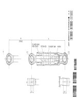
1. Steering cylinder
2. Sensor (only for 4WS)
3. Nut
4. Spacer
5. Nut
6. Pin cotter
2WS version
a. b Port - From swivel joint (2 Port)
b. a Port - From swivel joint (1 Port)
4WS version
a. b Port - From swivel joint (2 Port)
b. a Port - From OP1 solenoid valve group
(T Port)
Steering cylinder
10-7
PW75R-2
Sezione A - A
a
2
b
A
A
B
4
3
6
5
Particolare B
1
Particolare B
Solo per 2WS con
attrezzatura posteriore
Solo per 2WS con
attrezzatura anteriore
e per 4WS
RKP0
8870
Only for 2WS with
rear attachment
Only for 2WS with front
attachment and for 4WS
Detail B Detail B
Section A - A