FLOATING BREAKWATER RESPONSE TO WAVE ACTION
Bạn đang xem bản rút gọn của tài liệu. Xem và tải ngay bản đầy đủ của tài liệu tại đây (185.82 KB, 12 trang )
CHAPTER 162
FLOATING BREAKWATER RESPONSE TO WAVE ACTION
Michael Isaacson1, M.ASCE and Ronald Byres2
ABSTRACT
The present paper describes a study carried out to investigate floating
breakwater behavior in waves. Components of the study include a field
survey of floating breakwaters in British Columbia, Canada, the
development of a numerical model of breakwater behavior and the
experimental testing of a particular breakwater design. The numerical
model has been developed to provide breakwater motions, transmission
coefficients and mooring forces. The model combines linear diffraction
theory for obliquely incident waves, a mooring analysis, the inclusion of
viscous damping coefficients obtained from experimental or field data,
and the inclusion of drag and wave drift forces for use in the static
analysis of the moorings. The experiments were carried out with
normally incident regular waves of different heights and periods.
Preliminary results indicate that the numerical model should prove to be a
useful tool in floating breakwater design.
INTRODUCTION
Floating breakwaters have found extensive application in many areas
where relatively inexpensive protection from wind- and ship-generated
waves is required and where open water wave conditions are not unduly
severe and water depths are relatively large. The cost of traditional
bottom-founded breakwaters increases significantly with water depth, so
that a floating breakwater is a relatively attractive option in deeper water.
Professor, Department of Civil Engineering, University of British Columbia,
Vancouver, B.C. Canada.
2
Engineer, Sandwell Swan Wooster, 1190 Hornby Street, Vancouver, B.C. Canada.
2189
2190
COASTAL ENGINEERING — 1988
A considerable literature on the subject has developed over the past
decades, with the large variety of specific breakwater designs as well as
the large number of areas of potential application having contributed to
this wealth of information. Western Canada Hydraulics Laboratory
(1981) carried out an extensive literature survey, covering topics ranging
from analytical models of breakwater behavior to in-situ experiences with
particular breakwater designs.
Numerical methods of describing breakwater response to waves have
originated largely from ship hydrodynamics. Several authors have
treated the two-dimensional problem of wave interaction with cylinders at
or near the water surface by considering the corresponding potential flow
problem and solving this to calculate the hydrodynamic coefficients
necessary to determine the fluid forces on, and the motions of the
cylinder. In particular, the case of oblique wave interaction with
cylinders has been investigated by Bai (1975), Garrison (1969, 1984),
Isaacson and Nwogu (1987) and others. Field studies involving prototype
floating breakwaters are relatively uncommon. A number of authors
have published field data including Nelson et al. (1983), Nece and
Skjelbreia (1984) and Miller and Christensen (1984). Comparisons of
field data with laboratory tests and numerical models have generally
indicated that the response of breakwaters can be modeled quite well.
However, one difficulty is that responses are lower than the inviscid
theory predictions at frequencies near the resonant frequencies of the
breakwater, primarily because of additional energy dissipation associated
with flow separation.
The present paper describes a study carried out to investigate floating
breakwater behavior in waves, with components of the study including a
survey of floating breakwaters in British Columbia, Canada; the
development of a numerical model of breakwater behavior which predicts
transmission coefficients, breakwater motions and mooring forces for a
specified breakwater/mooring system and specified incident wave
conditions; and thirdly the experimental testing of a particular floating
breakwater design.
FLOATING BREAKWATERS IN BRITISH COLUMBIA
British Columbia, Canada, contains relatively large areas of sheltered
coastal waters, associated with protection from the open ocean provided
by Vancouver Island and the presence of a large number of inlets and
sounds. There is extensive use of pleasure craft in the region and a
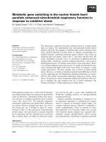
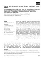
considerable number of floating breakwaters are located here. Locations
of thirty more significant floating breakwaters presently in use in British
Columbia are indicated in Fig. 1. In general, three categories of
breakwater have been used:
FLOATING BREAKWATER RESPONSE
Fig. 1.
Floating breakwater locations in British Columbia.
2191
2192
•
•
•
COASTAL ENGINEERING—1988
concrete caisson breakwaters, which generally have a rectangular
cross-section,
log bundles, which generally have a circular or raft-like cross
section,
A-frame breakwaters, which generally include two pontoons and a
central vertical plate.
These primarily rely on wave reflection to reduce transmitted wave
heights. In addition, a scrap tire breakwater, which reduces the
transmitted wave heights primarily by energy dissipation, is used at one
location. Table 1 lists floating breakwaters in British Columbia
corresponding to the locations shown in Fig. 1 and includes summary
information on the fetch and principal wind direction for each location.
Of the thirty breakwaters listed, eleven are caisson, fifteen are log and
two are A-frame. Typical design wave conditions correspond to a wave
period of about 4 sec and significant wave height of about 0.5 m. In
addition, there is generally a large tidal range of up to about 5 m. The
majority of breakwaters have generally provided quite satisfactory
service. This is particularly true of the concrete caissons which tend to be
more durable than the other designs and which are more amenable to
secondary usage. Although they have an initially higher capital cost, the
concrete breakwater systems have a lower incidence of structural damage
and provide a greater degree of wave attenuation than either scrap tire
breakwaters or log bundles.
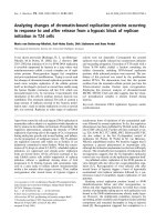
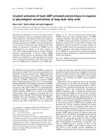
As one example of a concrete caisson breakwater, a new three-module
caisson breakwater was installed at Lund in May, 1987, replacing an
earlier A-frame which had served at that location for 22 years. A
photograph of the new breakwater during installation is shown in Fig. 2.
Lund is perhaps exposed to the most severe wave climate of any caisson
breakwater in the Strait of Georgia. The site is exposed primarily to
waves from the southwest and northwest, with fetches of about 30 km and
12 km respectively. The layout of the breakwater is somewhat unusual in
that the caisson sections are not inter-connected, but rather are staggered
in the horizontal plane in an effort to avoid problems arising with interconnections or collisions between units. The disadvantages of this
arrangement include a reduction in the potential area of protection
(because of the overlap of the sections), a reduction in the potential
degree of protection because of wave diffraction through the gaps, and a
relatively complicated mooring line arrangement.
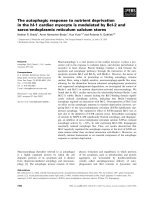
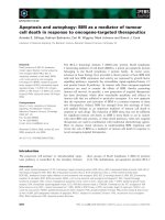
Floating log bundles are used extensively throughout British Columbia,
although in their simplest application - a mere boom of single logs they are not particularly effective against any but the shortest period
waves. An example at Reed Point Marina is shown in Fig. 3, and
indicates wave reflection and diffraction around the end of the log bundle
breakwater. In this case, the waves were caused by the passage of a tug
and are estimated to have a height of 0. 5 m and period of 3 sec.
FLOATING BREAKWATER RESPONSE
Fig. 2.
Fig. 3.
2193
The new caisson breakwater at Lund during installation.
The log bundle at Reed Point Marina, showing wave
reflection and diffraction.
2194
COASTAL ENGINEERING—1988
The A-frame breakwater at Lund which was in use until 1987 is shown in
Fig. 4. The breakwater has steel pontoons of diameter 0.76 m, a beam of
7.6 m, and a draft of 3.7 m. The timber centerboard is connected to the
pontoon with a steel space-frame, and extends upwards from the still
water level approximately 2 m. The identical design has been used for
the A-frame breakwater at Queen Charlotte City.
Only one breakwater in British Columbia involves scrap tires and is
located at Eagle Harbor. The breakwater consists of two rows of
cylindrical steel pontoons between which scrap tires are strung on
conveyor belting.
A unique floating breakwater at Powell River comprises of ten old
concrete-hulled ships and is shown in Fig. 5. This has been in use since
about 1930, having been gradually expanded to the present configuration
by the use of additional ships. The ships range in length from 102 m to
128 m and are anchored with eight to ten concrete anchors, each weighing
up to 14.5 tonnes.
Although the breakwaters indicated in Table 1 have generally provided
satisfactory service, possible difficulties which have been reported to arise
with floating breakwaters have involved their inability to provide
adequate wave protection, and possible damage or failure most often
associated with connections between individual units of a breakwater or
with its moorings.
NUMERICAL MODEL
A numerical model of floating breakwater behavior due to wave action
has been developed. Linear diffraction theory is used for a twodimensional breakwater section to provide the breakwater motions and
transmission and reflection characteristics for a regular, obliquely
incident wave train. The method has been described by Isaacson and
Nwogu (1987) and is based on a boundary integral equation approach
deriving from Green's theorem. The breakwater is treated as an
infinitely long horizontal cylinder and the fluid is assumed incompressible
and inviscid and the flow irrotational so that potential flow theory is used.
The velocity potential O of the flow is considered to be made up of
components associated with the incident waves <t>0, the diffracted waves
which would arise if the cylinder were fixed, <|>4, both of these
components being proportional to the incident wave height H, and forced
waves associated with each of three modes of motions of the cylinder, fy,
02 and $3, corresponding to sway, heave and roll respectively. The latter
potentials are proportional to the amplitude of the motion £j of each
mode. Thus the total velocity potential is expressed as:
FLOATING BREAKWATER RESPONSE
2195
Fig. 4.
The A-frame breakwater at Lund (removed in 1987).
Fig. 5.
The floating breakwater at Powell River, comprised of ship
hulls.
2196
COASTAL ENGINEERING — 1988
-icoH t
~7T~ (<t>o + 04)
+
^ _
Z"100^^ exp[i(kysinp - cot)]
(1)
J=l
where i = V^F, co is the wave angular frequency, y is the distance along the
cylinder axis, P is the angle the incident wave crests make with the
cylinder axis, k is the wave number, and t is time.
The equation of motion of the breakwater can be expressed in the usual
way as:
X [-co2(mij + aij) - ico(bij + by) + cy] Sj = Fj for i = 1, 2, 3
(2)
where my and cy are the mass and hydrostatic stiffness coefficients; and ay
and by are the added mass and damping coefficients associated with the
hydrodynamic forces, and F; are the exciting force amplitudes, by
represents an empirical damping coefficient accounting for viscous effects
which is used to modify motion predictions from those based solely on
potential theory. The hydrodynamic coefficients ay, by and F; may be
obtained in terms of the potentials 0O, ...,
wave heights to the incident wave height, are also of interest and are
obtained by computing wave conditions on control surfaces upstream and
downstream of the structure.
A suitable extension of this program provides the response to a random
incident wave train, which may be obliquely incident, and which may be
short-crested (see Isaacson and Nwogu, 1987). In particular, the program
provides spectra of the transmitted wave train and of the component
breakwater motions. These may be used to estimate the maximum
transmitted wave heights and breakwater motions for a storm of specified
duration.
The program may be used in conjunction with a three-dimensional
mooring analysis program, which utilizes the predicted breakwater
motions to provide maximum mooring line tensions.
EXPERIMENTAL STUDY
Laboratory experiments have been carried out to measure transmission
coefficients and breakwater motions using two particular breakwater
models subjected to normally incident, regular waves. One is a
rectangular section breakwater, while the other is an A-frame
breakwater. Measurements have been made of the breakwater motions
and of the transmission coefficient for a range of incident wave
conditions.
FLOATING BREAKWATER RESPONSE
2197
The experiments were carried out in the wave basin of the Hydraulics
Laboratory at the University of British Columbia. This is 14 m long, 5 m
wide and can accommodate water depths up to 0.45 m and wave periods
ranging from about 0.5 to 1.5 sec. A variable speed electrically driven
wave paddle at one end of the basin was used to provide regular longcrested waves, with the amplitude and period varied by adjusting the
stroke and frequency of the paddle. A sloping beach consisting of a
frame covered with artificial hair matting was located at the opposite end
of the basin to reduce wave reflections. Capacitance type wave probes
were used to measure the incident and transmitted wave heights. For all
the tests, a vertical wall was installed in the basin to prevent waves
reflecting from the model from interfering with the incident wave signal.
The rectangular breakwater used was based on the concrete caisson
breakwater employed in field tests reported by Nece and Skjelbreia
(1984). This corresponds to a prototype beam of 4.8 m, a length of 23 m
and a draft of 1.1 m, and the model was constructed to a scale of 1/15.
Experiments were carried out at several different wave periods, with
separate tests carried out at each wave period with waves of low and high
steepnesses.
The transmission coefficient was measured by the use of wave probes, and
the breakwater motions were measured by an optical system. Three
reference markers were attached to the model at known positions
vertically above the breakwater's center of gravity, with fixed scales
located behind each target. The amplitudes of motion, but not the phases,
were measured by sighting the targets and scales through a theodolite, and
aligning the cross-hairs in turn on each target at its maximum horizontal
or vertical excursion. Simple algebraic formulae were used to relate
these motion amplitudes to those of the breakwater's center of gravity.
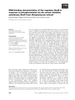
A preliminary comparison with numerical predictions for the case of the
rectangular breakwater has been carried out and selected results are
indicated in Figs. 6 and 7. In the figures, a is the half beam of the
breakwater. Fig. 6 compares numerical results of the transmission
coefficient with measured values, as well as with the field measurements
reported by Nelson et al. (1983) and Nece and Skjelbreia (1984). There
is considerable scatter in the measured values so that the comparison is
somewhat inconclusive. The values obtained from field measurements are
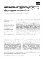
relatively high and relatively insensitive to wave frequency. Fig. 7 shows
the heave response amplitude operator, with the numerical predictions
based on various values of the viscous damping coefficient. The trend of
the response to reduce with increasing wave frequency is apparent.
As expected, the numerical predictions confirm that the breakwater is
most effective for higher frequency waves, corresponding approximately
to B/L > 0.3, where B is the width of the rectangular section and L is the
incident wave length. The roll and sway motions exhibit strong resonant
peaks, which are quite sensitive to the value of the viscous damping
COASTAL ENGINEERING— 1988
2198
s
'o
ss
o
c
o
ka
Fig. 6.
1)
•a
%
4>
Numerical, laboratory and field results of the transmission
coefficient for the rectangular breakwater.
1.8
1.7
1.6
1.5
1.4
1.3
1.2
1.1
1
0.9
0.8
0.7
0.6
0.5
0.4
0.3
0.2
0.1 H
0 02
Undamped
5 % Damping
10 % Damping
15 % Damping
Measured (High)
Measured (Low)
0.6
1
1.4
1.8
2.2
2.6
ka
Fig. 7.
Numerical and laboratory results of the heave response
amplitude operator for the rectangular breakwater.
FLOATING BREAKWATER RESPONSE
2199
coefficient selected. With only 5% damping, these resonant peaks are all
but removed, which is consistent with the observations of other studies
(e.g. Miller and Christensen, 1984).
CONCLUSIONS
Floating breakwaters are a viable means of providing wave protection in
areas where incident wave conditions are not too severe and water
depths are relatively large. They have been widely used in British
Columbia, Canada. Although experience in British Columbia has not
revealed major difficulties in the use of floating breakwaters, other
reported difficulties associated with their use include a possible inability
to provide adequate protection from waves, and possible damage or
failure most often associated with connections between individual units of
a breakwater or with its moorings.
A numerical model based on linear diffraction theory and extended to
include the effects of moorings, obliquely incident, random waves and
additional damping has been developed. The program has been verified
in part against laboratory measurements and should be quite viable for
use in floating breakwater design. Laboratory tests have been carried
out, but a comparison with numerical predictions is somewhat
inconclusive.
APPENDIX
-
REFERENCES
Bai, K.J. 1975. "Diffraction of oblique waves by an infinite cylinder,"
Journal of Fluid Mechanics, 68, pp. 513-535.
Garrison, C.J. 1969. "On the interaction of an infinite shallow-draft
cylinder oscillating at the free surface with a train of oblique waves,"
Journal of Fluid Mechanics, 39, pp. 227-255.
Garrison, CJ. 1984. "Interaction of oblique waves with an infinite
cylinder," Applied Ocean Research, 6 (l),.pp. 4-15.
Isaacson, M. and Nwogu, O. 1987. "Directional Wave Effects on Long
Structures," Journal of Offshore Mechanics and Arctic Engineering,
109 (2), pp. 126 - 132.
Miller, R.W., and Christensen.D.R. 1984. "Rigid body motion of a
floating breakwater," Proc. International Conf. on Coastal Engineering,
Houston, Texas, pp. 2663-2679.
Nece, R.E., and Skjelbreia. 1984. "Ship-wave attenuation tests of a
prototype floating breakwater," Proc. International Conf. on Coastal
Engineering, Houston, Texas, pp. 2515-2529.
COASTAL ENGINEERING—1988
2200
Nelson, E.E., Christensen, and Schuldt, A.D. 1983. "Floating
breakwater prototype test program." Proc. Conf. Coastal Structures '83,
ASCE, pp. 433-446.
Western Canada Hydraulics Laboratory. 1981. "Development of a manual
for the design of floating breakwaters." Canadian Manuscript Rept. of
Fisheries and Aquatic Sciences, No. 1629, Small Craft Harbors Branch,
Dept. of Fisheries and Oceans, Ottawa, 228 pp.
Table 1.
Summary of Floating Breakwaters in British Columbia
No.
Location
Type
Year
Fetch
(km)
1
2
3
4a
4b
Richmond
Port Moody
Deep Cove
BurrardYC
BurrardYC
(Destroyed 1983)
Eagle Harbour
Horseshoe Bay
Powell River
Lund
Lund
(Removed 1987)
Brown Bay
Fanny Bay
Deep Bay
Ford Cove
Northwest Bay
(Destroyed 1980)
Nanaimo
Nanaimo
Nanaimo
Pt Browning
Bedwell Hbr
Maple Bay
Victoria Hbr
Esquimault
Becher Bay
Sooke Basin
Prince Rupert
Prince Rupert
Qn Charlotte City
Qn Charlotte City
Kelowna
Nakusp
Tahsis
Caisson
Log Bundle
Caisson
Caisson/barge
Scrap tire
1979
1976
1976
1977
1977
1.7
0.8
5.5
3.1
3.1
W
NE
NE
E
E
Pontoon / tire
Caisson / ship
Ship Hull
Caisson
A-frame
1977
39.1
9.0
28.7
29.6
29.6
SW
N
SW
SW
SW
E
NE
W
NW
5
6
7
8a
8b
9
10
11
12
13
14
15
16
17
18
19
20
21
22
23
24
25
26
27
28
29
30
1930+
1987
1963
Dim.
Tank Car
Log Bundle
Log Bundle
Log Raft
Log / Styrofoam
1975
2.8
2.6
2.2
6.5
37
Caisson
1974
0.2
5.3
E
SE
2.1
3.0
4.3
0.5
1.8
1.5
1.9
SE
NW
NE
S
SW
SE
SW
Log
Log
Caisson
Caisson
Caisson
Log
Log
Log
Log
Log
A-frame
Log Bundle
Caisson
Log
1983
1977
1967
1978
1986
4.4
2.4
W
2.8
SE