Shop Manual & ETM BCM KIA Cerato 2010 - Audio
Bạn đang xem bản rút gọn của tài liệu. Xem và tải ngay bản đầy đủ của tài liệu tại đây (983.68 KB, 34 trang )
2010 > G 1.6 DOHC > Body Electrical System
Specification
Audio
Item Specification
Model
RADIO/CD
(A100)
RADIO/CD/MP3
(A200)
RADIO/CDC/MP3
(A300)
Power supply DC 14.4V
Rated output Max 43W x 4 Min. 12W
Antenna 80PF 75Ω
Tuning type PLL SYNTHESIZED TUNING
Frequency range / Channel
space
FM 87.5 ~ 108.0 MHz/100 KHz (for General)
AM 531 ~ 1602 KHz/9 KHz (for General)
FM 87.5 ~ 108.0 MHz/50 KHz (for Europe)
MW 522 ~ 1620 KHz/9 KHz (for Europe)
LW 153 ~ 279 KHz/1 KHz (for Europe)
Speaker
Item Specification
Input Power
(W)
Front 20 (Max. 30)
Rear 20 (Max. 30)
Tweeter 20 (Max. 30)
Speaker Impedance
(Ω)
Front 4.0 ± 0.6
Rear 4.0 ± 0.6
Tweeter 3.4 ± 0.5
Speaker Number 6
Language
2010 > G 1.6 DOHC > Body Electrical System
Component Location
1. Audio unit
2. Tweeter speaker
3. AUX Jack / USB Port
5. Front door speaker
6. Rear door speaker
7. Antenna feeder cable
Language
4. Antenna cable connector 8. Roof antenna (Radio)
2010 > G 1.6 DOHC > Body Electrical System
Components
Language
2010 > G 1.6 DOHC > Body Electrical System
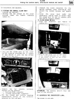
Removal
1. Disconnect the negative (-) battery terminal.
2. Remove the center air vent (B) using the SST (A)
(09840-1M100). (Refer to the Body group - Crash
pad)
Always use the SST(09840-1M100) to prevent the damage when removing the air vent. (Refer to the
Body group - Crash pad)
3. Remove the crash pad center facia panel (A).
Take care not to scratch the crash pad and related parts.
Language
4. Disconnect the connectors(A) from the crash pad center facia panel and heater control unit.
5. Remove the mounting bolts(4EA) then remove the audio unit(A).
6. Disconnect the audio connectors and cable(A).
Installation
1. Connect the audio unit connectors and cable.
2. Install the audio unit.
3. Install the crash pad center facia panel.
4. Check the audio system.
• Make sure the audio head unit connectors are plugged in properly, and the antenna cable is
connected properly.
Disassembly
1. Disassemble the front panel(A) then disconnect the connector(B) between the unit and front panel.
2. Disassemble the top cover(A) after loosening 4 screws.
3. Disassemble the deck (A) from the unit after removing the connector and screws.
Reassembly
1. Reassemble the deck to the audio unit.
2. Reassemble the top cover.
3. Reassemble the front panel and connect the connector.
2010 > G 1.6 DOHC > Body Electrical System
Components
Language
2010 > G 1.6 DOHC > Body Electrical System
Circuit Diagram
2010 > G 1.6 DOHC > Body Electrical System
Description
Language
Language
Advanced lighting speaker
The advanced lighting speaker that lights around the front speaker is adjusted by turning the knob.
• ON : The light turns on.
• MOOD : The light shade changes automatically at regular interval.
• MUSIC : The light blinks or changes shade according to the sound of audio.
• OFF : The light turns off.
• +/- : When the lights are on, push the illumination button to adjust the light intensity.
2010 > G 1.6 DOHC > Body Electrical System
Removal
Mood Lamp
1. Remove the front door trim.
(Refer to the BD group - "Front door")
2. Remove the mood lamp (A) after loosening the screws (4EA).
Mood Lamp Switch
1. Disconect the negative (-) battery terminal.
2. Remove the lower panel (A).
(Refer to the BD group - "Crash pad")
Language
3. Remove the pin (A) of hinge in direction of the arrow.
4. Remove the mood lamp switch (A) after loosening the screws (4EA).
Front Speaker
1. Remove the front door trim.
(Refer to the BD group - "Front door")
2. Remove the front speaker (A) after removing 4 rivets.
Rear Speaker
1. Remove the rear door trim.
(Refer to the BD group - "Rear door")
2. Remove the rear speaker (A) after removing 4 rivets.
Tweeter Speaker
1. Remove the front door delta cover.
(Refer to the BD group - "Front door")
2. Remove the tweeter speaker (A) after disconnecting the connector.