Steel Casting Handbook
Bạn đang xem bản rút gọn của tài liệu. Xem và tải ngay bản đầy đủ của tài liệu tại đây (1.66 MB, 34 trang )
STEEL
CASTINGS
HANDBOOK
SUPPLEMENT 3
2003
DIMENSIONAL CAPABILITIES
OF STEEL CASTINGS
1
SFSA Supplement 3
DIMENSIONAL CAPABILITIES OF STEEL CASTINGS
1. Introduction
Dimensional tolerances are selected by the designer or purchaser to make sure that the part can
perform its function reliably and fit into its designed location. Assigning dimensions to a part
requires identifying the desired feature size. Tolerances communicate how much variation from
the desired size can be tolerated. Overly stringent tolerances are costly and do not add value.
They require added work to meet tolerances that may be beyond the process capability.
Inadequate tolerances are a problem because parts may be able to meet the tolerance but fail to
either fit or function in accordance with the design.
To assign dimensions and tolerances to a part that is produced as a casting involves
consideration of function and fit of the finished part, allowances for machining operations involved
in producing the finished part, and production requirements such as draft and taper. Allowances
for castings and the major tolerance considerations in the production of parts as steel castings
are presented below. Along with this information a set of tolerance grades is introduced to
facilitate communication on tolerances.
2. Allowances
The shapes of cast steel components reflect not only the functional requirements of the
component, but also manufacturability requirements dictated by the casting process. Castings
shapes must incorporate the proper use of draft allowances for successful mold making and
machining allowances for surfaces requiring more precision and better surface finishes than can
be achieved in the as-cast conditions. Draft and machine finish allowance guidelines and
practices are presented to assist in the specification of draft and machining allowances for
castings.
Similarly, size or pattern allowances must be incorporated into the production of patterns and
coreboxes from which steel castings are made. These pattern allowances (sometimes call shrink
rules) must also be correctly applied to ensure that final castings can meet customer dimensional
tolerance requirements without extra pattern dimension adjustment cycles. Other castability
guidelines that influence the recommended geometry of steel castings are discussed in “Steel
Casting Design”.
1
2.1 Draft (Taper) Allowances
Draft should be designated on the casting drawing in consultation with the casting producer—
typically in a drawing note. The draft angle selected should be no less than can be tolerated in
the design. Figure 2.1 illustrates the use of draft on a typical pattern and corebox.
2
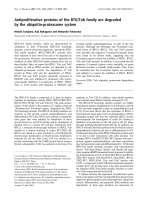
Figure 2.1 - Schematic illustration of a full split pattern and core box to produce a wheel-
type casting. Note that draft is required on the vertical surfaces to allow the pattern to be
drawn away from the mold. The core that will be made in the core box will form a
cylindrical cavity to reduce machining.
2.1.1 Draft (Taper) Allowance Recommendations
Table 2.1 presents general draft recommendations for steel castings. To ensure moldability, it is
helpful to meet or exceed these draft allowances indicated on all surfaces perpendicular to the
mold parting line.
Table 2.1: Typical Draft (Taper) Allowances
Typical Draft (Taper) Angles
Molding Process
Most Features Deep Pockets
Green Sand - Manual 1.5 ° 2.0 °
Green Sand - Automated 1.0 ° 1.5 °
No-bake & shell molding 1.0 ° 1.5 °
2.1.2 Factors Affecting Recommended Draft Allowances
Machine molding will require a minimum amount of draft. Interior surfaces in green sand molds
usually require more draft than exterior surfaces. Draft can be eliminated in some cases through
special molding techniques, such as investment casting or through the use of cores. These
situations and the specific amount of draft required should be discussed with personnel of the
foundry that will produce the casting.
3
A specific dimensional tolerance on a drafted surface is generally referenced from the drafted
surface rather than from the surface dimension before draft is applied. That is, draft is added to
casting surfaces first before dimensional tolerances or geometric tolerances applied, Figure 2.2.
Draft allowances can be incorporated into dimensional tolerances or geometric tolerances only
upon consultation with the
foundry.
The dimensional changes needed to incorporate draft can be expressed as follows:
DA = L tan θ
Where:
DA = Draft allowance
L = Length
θ = Draft angle
4
Figure 2.3 Dimensional tolerance zones on drafted (tapered) features (CT is the casting
dimensional tolerance as defined in ISO- 8062)
2.2 Required Machining Allowance Guideline
Castings that are to be machined must have sufficient metal stock on all surfaces requiring
machining. The necessary allowance, commonly called the required machining allowance
(RMA), machine finish allowance, or machining allowance, depends upon the size and shape of
the casting, the surface to be machined, the hardness of the steel, roughness of the casting
surface, and the tendency to distort. The required machining allowance is superimposed upon
draft and pattern allowances. Required machining allowances are typically called out in drawings
with a general note.
5
2.2.1 Required Machining Allowance
Table 2.2 - Required machining allowances (RMA) in millimeters for steel castings based
on ISO 8062.
Largest dimension
mm
Required machining allowance
mm
Note: A minimum of 6 mm RMA required on all cope casting surfaces
Required machining allowance grade over up to and
including
E F G H J K
-
40 0.4 0.5 0.5 0.7 1 1.4
40 63 0.4 0.5 0.7 1 1.4 2
63 100 0.7 1 1.4 2 2.8 4
100 160 1.1 1.5 2.2 3 4 6
160 250 1.4 2 2.8 4 5.5 8
250 400 1.8 2.5 3.5 5 7 10
400 630 2.2 3 4 6 9 12
630 1000 2.5 3.5 5 7 10 14
1000 1600 2.8 4 5.5 8 11 16
1600 2500 3.2 4.5 6 9 13 18
2500 4000 3.5 5 7 10 14 20
4000 6300 4 5.5 8 11 16 22
6300 10000 4.5 6 9 12 17 24
Sand casting, hand molded → use grade G – K
Sand casting, machine molded (and shell) → use grade F – H
Investment casting → use grade E
6
Table 2.2 - Required Machining allowance (RMA) in inches for steel castings based on ISO
8062.
Largest dimension
in.
Required machining allowance
mm
Note: A minimum of 0.25 in. RMA
Required machining allowance grade over up to and
including
E F G H J K
-
1.6 0.016 0.020 0.020 0.028 0.040 0.055
1.6 2.5 0.016 0.020 0.028 0.040 0.055 0.080
2.5 4 0.028 0.040 0.055 0.080 0.110 0.160
6 10 0.055 0.080 0.110 0.160 0.220 0.320
10 16 0.070 0.100 0.140 0.200 0.280 0.400
16 25 0.087 0.120 0.160 0.240 0.360 0.480
25 40 0.100 0.140 0.200 0.280 0.400 0.560
40 60 0.110 0.160 0.220 0.310 0.430 0.630
60 100 0.130 0.180 0.240 0.350 0.510 0.710
100 160 0.140 0.200 0.280 0.390 0.550 0.790
160 250 0.160 0.220 0.310 0.430 0.630 0.870
250 400 0.180 0.240 0.350 0.470 0.670 0.940
2.2.2 Factors Affecting Required Machining Allowances
The allowances expressed in Table 2.2 are conservative and should apply to short production run
castings. They may be reduced for high production run castings when adequate preliminary
consultation and machining trials have been carried out. Machine allowances for castings of very
large size, such as greater than 15 ft (5000mm), should be determined through consultation with
the foundry.
The required machining allowance, when considered along with the casting feature dimensional
tolerance, should be interpreted as shown in Figure 2.4.
7
A – Machining on one side of feature
B – External machining of boss
8
C – Internal machining
D – Machining of step dimension
Figure 2.4 Interpretation of required machining allowances along with casting feature
tolerances.
The dimensional allowance to be added to the casting section for machining purposes will
depend on the design of the casting. Certain faces of a casting may require larger allowances
than others as a result of their position in the mold. In particular, the cope surfaces of a large
casting will require larger machining allowances than the drag surfaces or side walls. For cope
surfaces in particular required machining allowances for cope surfaces of less than 0.25 inches
(6mm) are generally not recommended. For this reason, it is recommended that critical machined
surfaces be molded in the drag whenever possible.
Sufficient excess metal should be allowed to satisfactorily accomplish the necessary machining
operations. One very good rule is to allow enough “machining stock” so that the first cut remains
below the cast surface on the metal by at least 1/16 in. (1.5 mm). Required machining
allowances must be chosen with care. Critical surfaces that are fixtured using as-cast locators are
sometimes preferred to avoid excess machine stock on critical surfaces.
9
3. Dimensional Tolerances
Tolerances for dimensions of as-cast features are a matter for agreement between the producer
and purchaser (We do not know who the consumer is) of the castings. However, to minimize the
rejection of castings for dimensional reasons, the tolerances selected should be compatible with
the capability of the process selected.
Tolerances affect the cost and delivery of the castings. Most castings have only a few critical
dimensions which require tight tolerances. Placing tight tolerances on dimensions which are not
critical merely increases the final casting cost without benefit to the purchaser. However, where
tolerances tighter than the process can normally produce are required, dimensional upgrading
using one of the operations discussed later may be the least expensive method of satisfying the
requirements.
The best way to make this determination is through a joint effort in a value engineering or value
analysis project. Good communications of requirements on the one hand and the processes
needed to meet them on the other is the key.
The International Organization for Standardization (ISO) has issued, ISO 8062, Castings –
System of Dimensional Tolerances. This standard provides a system of tolerances and machining
allowances for all castings, including steel castings. It assigns different dimensional tolerance
grades based on the metal cast, the molding process used, the length of the casting feature, and
the production quantity. The ISO 8062-1994 tolerancing scheme is the basis from which
improved dimensional tolerances for steel castings have been developed by the SFSA. These
SFSA 2000 steel casting dimensional tolerances should be used instead of the specific steel
casting tolerance recommendation contained within ISO-8062-1994 for steel castings.
These new dimensional tolerance also supersede the 1997 (SFSA developed) “T grades”
dimensional tolerances.
The production quantities, the casting design and the dimension type play an important role in
determining the tolerances which can be met with the process
because the complex contraction
behavior of steel during solidification and cooling must be adequately compensated for in the
construction of the pattern. The production of castings in large numbers usually provides the
opportunities to make dimensional adjustments in pattern equipment or to compensate for
unpredictable casting contraction behavior with one or more reverse engineering steps. These
costly reverse engineering steps to adjust pattern dimensions are a function of the dimensional
tolerance requirements established by the customer as well as the foundry’s process variability.
The SFSA-2000 dimensional tolerances presented here are based on a statistical analysis of
more than 140,000 casting features on production steel castings weighing from 6.5 to 12,000 lbs.
for common steel molding processes. The dimensional capabilities from which these tolerances
have been developed account for both the expected casting process variability and dimension
centering errors that can be expected for typical short production series and long production
series casting production, Tables 3.1-3.4.
10
3.1 SFSA 2000 Dimensional Tolerances for Steel Castings
Table 3.1 Casting dimensional tolerance grades from ISO 8062-1994. These grade
designations also used for SFSA 2000 steel casting tolerances
Raw Casting
basic
dimensions,
Total casting tolerance
mm
mm
Casting tolerance grade CT
Over Up to &
including
1 2 34567891011 12 13 1415 16
- 10 0.09 0.13 0.18 0.26 0.36 0.52 0.74 1 2 2 2.8 4.2 - - - -
10 16 0.10 0.14 0.20 0.28 0.38 0.54 0.78 1.1 1.6 2.2 3 4.4 - - - -
16 25 0.11 0.15 0.22 0.3 0.42 0.58 0.82 1.2 1.7 2.4 3.2 4.6 6 8 10 12
25 40 0.12 0.17 0.24 0.32 0.46 0.64 0.9 1.3 1.8 2.6 3.6 5 7 9 11 14
40 63 0.13 0.18 0.26 0.36 0.50 0.70 1 1.4 2 2.8 4 5.6 8 10 12 16
63 100 0.14 0.20 0.28 0.40 0.56 0.78 1.1 1.6 2.2 3.2 4.4 6 9 11 14 18
100 160 0.15 0.22 0.30 0.44 0.62 0.88 1.2 1.8 2.5 3.6 5 7 10 12 16 20
160 250 - 0.24 0.34 0.50 0.70 1 1.4 2 2.8 4 5.6 8 11 14 18 22
250 400 - - 0.40 0.56 0.78 1.1 1.6 2.2 3.2 4.4 6.2 9 12 16 20 25
400 630 - - - 0.64 0.90 1.2 1.8 2.6 3.6 5 7 10 14 18 22 28
630 1000 - - - - 1 1.4 2 2.8 4 6 8 11 16 20 25 32
1000 1600 - - - - - 1.6 2.2 3.2 4.6 7 9 13 18 23 29 37
1600 2500 - - - - - - 2.6 3.8 5.4 8 10 15 21 26 33 42
2500 4000 - - - - - - - 4 6.2 9 12 17 24 30 38 49
4000 6300 - - - - - - - - 7 10 14 20 28 35 44 56
6300 10000 - - - - - - - - - 11 16 23 32 40 50 64
11
Table 3.2 Casting dimensional tolerances adapted from ISO 8062-1994, (inches), also
used for SFSA 2000 steel casting tolerances
Raw Casting
basic dimensions,
in.
Total casting tolerance
in.
Casting tolerance grade CT
Over Up to &
including
1 2 345678910 11 1213 14 15 16
- 0.4 0.01 0.01 0.01 0.01 0.01 0.02 0.03 0.04 0.06 0.08 0.11 0.17 - - - -
0.4 0.6 0.01 0.01 0.01 0.01 0.02 0.02 0.03 0.04 0.06 0.09 0.12 0.17 - - - -
0.6 1 0.01 0.01 0.01 0.01 0.02 0.02 0.03 0.05 0.07 0.09 0.13 0.18 0.24 0.32 0.39 0.47
1 1.6 0.01 0.01 0.01 0.01 0.02 0.03 0.04 0.05 0.07 0.1 0.14 0.2 0.28 0.35 0.43 0.55
1.6 2.5 0.01 0.01 0.01 0.01 0.02 0.03 0.04 0.06 0.08 0.11 0.16 0.22 0.32 0.39 0.47 0.63
2.5 4 0.01 0.01 0.01 0.02 0.02 0.03 0.04 0.06 0.09 0.13 0.17 0.24 0.35 0.43 0.55 0.7
4 6 0.01 0.01 0.01 0.02 0.02 0.04 0.05 0.07 0.1 0.14 0.2 0.27 0.39 0.47 0.63 0.79
6 10 - 0.01 0.01 0.02 0.03 0.04 0.06 0.08 0.11 0.16 0.22 0.32 0.43 0.55 0.7 0.87
10 16 - - 0.02 0.02 0.03 0.04 0.06 0.09 0.13 0.17 0.24 0.35 0.47 0.63 0.79 0.98
16 25 - - - 0.03 0.04 0.05 0.07 0.1 0.14 0.2 0.28 0.39 0.55 0.7 0.87 1.1
25 40 - - - - 0.04 0.06 0.08 0.11 0.16 0.24 0.32 0.43 0.63 0.79 0.98 1.26
40 60 - - - - - 0.06 0.09 0.13 0.18 0.28 0.35 0.57 0.7 0.91 1.14 1.46
60 100 - - - - - - 0.1 0.15 0.21 0.32 0.39 0.59 0.83 1.02 1.3 1.65
100 160 - - - - - - - 0.17 0.24 0.35 0.47 0.67 0.95 1.18 1.5 1.93
160 250 - - - - - - - - 0.28 0.39 0.55 0.79 1.1 1.38 1.73 2.21
250 400 - - - - - - - - - 0.43 0.63 0.91 1.26 1.58 1.97 2.52
Table 3.3 SFSA 2000 for steel casting tolerance long-production series.
Conditions
Select Tolerance
Grades
All sand molding process fully capable,
most appropriate for large castings
CT 12-14
Appropriate for most casting types and
sand molding processes
CT 10-12
Within process capabilities, but not
appropriate for all casting types and sand
molding processes
CT 8-10
Investment Casting
CT 5-7
12
Table 3.4 SFSA 2000 steel casting tolerances for short-production series steel castings
Conditions
Select Tolerance
Grades
All sand molding process fully
capable, most appropriate for large
castings
CT 13-15
Appropriate for most casting types
and sand molding processes
CT 11-13
Within process capabilities, but not
appropriate for all casting types and
sand molding processes
CT 9-11
Additional comments on the use of the SFSA 2000 steel casting dimensional tolerances can be
found in the Appendix.
3.2 Variables Affecting Dimensional Tolerances
The aforementioned steel casting dimensional tolerance recommendations are general
recommendations that can be readily used by casting customers. Comprehensive SFSA steel
casting dimensional capability studies have developed more detailed information on the process
and geometric factors influencing the repeatability of steel casting dimensions. Overall industry
dimensional capabilities as well as the capabilities of individual foundries are fully described.
This information can be used by foundries to benchmark their dimensional capabilities, and to
better quantify the effects of key variables affecting dimensional capabilities. The dimensional
capability data presented here includes measurement uncertainty multiplying factors applied to
the dimensional variability data from which it is based. This accounts for small non-centering
errors expected during tooling validation sampling. The short production series dimensional
capability prediction equations include a larger multiplying factor that accounts for non-centering
errors from less rigorous sampling for tooling validation.
Casting dimensional tolerance capabilities are expressed in terms of 10%, 50%, and 90%
capabilities as follows:
10% Capability = 10% of the feature capabilities were less than this limit.
50% Capability = Average capability.
90% Capability = 90% of the feature capabilities were less than this limit.
Figures 3.6-3.8 show the 10%, 50%, and 90% dimensional capabilities of 15 steel foundries using
various sand molding processes compared to ISO casting tolerance (CT) grades. The foundry-to-
foundry differences in dimensional capabilities reflect the broad range of casting sizes and
shapes produced and the different sand molding processes used, as well as differences in
process control. These keys factors influencing dimensional capabilities are presented here as a
guide to both the casting customer and the casting producer.