Analytical study to minimize the engine exhaust emissions and safe knock limit of CNG powered four-stroke SI engine
Bạn đang xem bản rút gọn của tài liệu. Xem và tải ngay bản đầy đủ của tài liệu tại đây (231.49 KB, 22 trang )
INTERNATIONAL JOURNAL OF
ENERGY AND ENVIRONMENT
Volume 1, Issue 1, 2010 pp.31-52
Journal homepage: www.IJEE.IEEFoundation.org
Analytical study to minimize the engine exhaust emissions
and safe knock limit of CNG powered four-stroke SI engine
Jeewan V. Tirkey, H.N. Gupta, S.K. Shukla
Mechanical Engineering Department, Institute of Technology, Banaras Hindu University, Varanasi221005, India.
Abstract
In this paper, theoretical analysis has been done to minimise engine emissions and safe knock limit by
changing some operational and design parameters such as equivalence ratio, spark plug location,
compression ratio, and cylinder diameter by using computer simulation model. For this purpose a zero
dimensional knock model, two zone combustion model(one in front and one behind the flame front), and
gas dynamic model have been incorporated. Subsequently, the Nitric Oxide exhaust emission
concentrations have been predicted by using the rate kinetic model in the power cycle and along the
exhaust pipes. Furthermore, Carbon Monoxide is computed under chemical equilibrium condition and
then empirical adjustment is made for kinetic behaviours based upon experimental results. It is
inferred that the value of cylinder pressure data, BMEP, BSFC obtained by using computer simulation
model based on theoretical analysis are in closer agreement with those which are obtained by previous
studies.
Copyright © 2010 International Energy and Environment Foundation - All rights reserved.
Keywords: Two-zone combustion, Onset knock limit, Percentage heat loss, Spark plug
Cylinder diameter by stroke ratio.
location,
1. Introduction
To meet the twin problems of fuel oil scarcity and air pollution caused by growing use of petroleum
fuels, an alternative renewable clean burning fuel CNG has been explored, as a most prominent ecofriendly fuel for use in SI engine vehicles. CNG is a promising alternative fuel to meet strict engine
regulation in many countries.
CNG powered engine offers certain advantages e.g. clean combustion (no lead or sulphur compound)
due to high H/C ratio, does not contaminate and dilute the engine oil which forms no deposits on spark
plug. It also offers advantage over gasoline in terms of its low density and ready miscibility with air, high
knock resistance (octane number 120-130), lean burning capability. Its results in smooth start during cold
season. However, due to lack of modification in available engines including supply of conversion kits, it
is difficult to fully utilize the above properties of CNG powered engine to enhance the performance.
The relative amounts of various pollutants depend on fuel composition (especially fuel –air equivalence
ratio), engine design and operating conditions. Many authors[1-3] found that the leaner mixtures give
lower quantities of CO and NO, but if the mixture is made too lean the engine may misfire, giving rise to
higher HC emissions. They also suggested that for obtaining maximum power the engine needs to
ISSN 2076-2895 (Print), ISSN 2076-2909 (Online) ©2010 International Energy & Environment Foundation. All rights reserved.
32
International Journal of Energy and Environment (IJEE), Volume 1, Issue 1, 2010, pp.31-52
operate near stoichiometric (slightly rich), while the best economy is obtained with a mixture somewhat
leaner than stoichiometric.
Emission modeling is essential for the sound theoretical understanding of the mechanisms for pollutants
formation. The pollutant formation processes are intimately linked with the primarily fuel combustion
process directly through environmental conditions created by these reactions. A simple estimation of the
concentration values of various products of combustion is possible assuming chemical equilibrium.
However, the concentrations of the pollutants in the exhaust tail pipe of ICE differ from values estimated
using chemical equilibrium conditions. Thus the detailed chemical mechanisms by which these pollutants
form and the kinetics of these processes are important in estimating emission levels. At the same time,
both flow rate and concentrations of each pollutant significantly affect mass emissions. The emission
modeling therefore is a complex art involving fluid mechanics and reaction kinetics. Benson-Horlock et
al. [2] reported one of the best technique to calculate 12 numbers of product species during equilibrium
condition. This technique has been greatly used by many researchers [4-8]. Furthermore, Agarwal et al.
[9, 10] have used detailed chemical kinetics mechanism which consisted of 22 species and 104
elementary reactions with KIVA-3 code in their engine modeling.
In engine emission species, specially NO formation, there are many reaction mechanisms proposed by
different authors namely Heywood [1], Horlock-Benson [2], Millar et al. [11]: Zeldovich (2 reactions),
Extended Zeldovich (3 reactions ), super extended Zeldovich (67 reactions ) and Lavoie ( 7 reactions).
These equations depend upon the engine operating conditions and accuracy of predictions. Similarly, CO
concentrations in exhaust gases are recognized to be kinetically controlled, because CO concentrations
are lower than the maximum value measured within the combustion chamber but higher than the
corresponding equilibrium value. For this, Benson2, Sher et al. [12] introduced COFAC factor, used to
predict CO concentrations, which lies between the peak and exhaust equilibrium values. The more
detailed information concerning pollution formation mechanism and their chemical kinetic rate of carbon
monoxides, organic compounds, and particulates are adequately discussed in the book of: HorlockBenson [2], Heywood [1], Turns [13]. Along with reduction of engine emission, the efficiency and power
of the engine are also equally important.
Combustion knock has long been one of the major barriers in the development of spark ignition engine
for increased efficiency or improved fuel tolerance. Checkel and Dale [14], Chun et al. [15], investigated
experimentally and computationally knock characteristics, such as intensity, percentage & occurrence
crank angle from pressure and vibration signal using different analysis methods e.g. band pass filter,
third derivative and step method . It was also reported that the vibration signal is more useful among
these methods.
Heywood [1], Chun et al. [15], Moses et al. [16], Checkel and Dale [14], By A et al. [17], König G et al.
[18], Ferguson et al. [3] reported that the knock is an acoustic phenomenon produced by the auto ignition
of the unburned gas in front of flame regime called end-gas. They also reported that the thermal
efficiency is directly related to the compression ratio, and engine knock occurs more easily if the
compression ratio is increased. In order to fully understand the knock phenomenon and to find possible
way to avoid knock phenomenon, Moses [16], and Soylu and Gerpen [19] discussed the categories of
knocking sub-model:
(1) Single zone zero dimensional model (Global model).
(2) Multi zone model (Burned and Unburned).
(3) Quasi dimensional model (neglecting the transverse variation in the gas flow field).
(4) Multidimensional model (real gas dynamic flow, detailed kinetic model, which contains several
hundred reactions).
They also reported that, the simplest and fastest way to model engine processes and gas auto ignition is
using a zero dimensional model with estimated initial conditions at intake valve closing and combining it
with global auto-ignition model.
Liberman [20] analyzed these models and inferred that the fuel conditions are described by the system of
ordinary differential equations that include terms corresponding to adiabatic compression: the
temperature rise due to exothermic reactions and energy losses to the cylinder walls.
Livengood and Wu [21] developed the first published ignition correlation for SI engine, which was
integrated form of an empirical model for onset occurrence based on ignition delay. The pressure and
temperature histories of a fired engine are used to determine knock onset. The most extensively tested
correlation for ignition delay is that proposed by Douaud and Eyzat [22] to determine the knock
resistance. The pre-exponential parameter was based on the Octane number of fuel and the end gas
ISSN 2076-2895 (Print), ISSN 2076-2909 (Online) ©2010 International Energy & Environment Foundation. All rights reserved.
International Journal of Energy and Environment (IJEE), Volume 1, Issue 1, 2010, pp.31-52
33
temperature. This model has been used as base by many researcher [1, 6, 23-25] by changing its
constants in their own Knock model for different fuel and engine design. The present work involves a
theoretical approach to develop a computational model of combustion in SI engine in order to understand
auto-ignition mechanism including knock phenomenon and way to reduce it. Also the validation of
model is being compared by experimental data provided by Baruah [2], Aslam [26] and Ma [27].
2. Computational model
The present model which consists of two main domains (1) Inlet and exhaust domain and (2) cylinder
domain, formally named as General simulation model (GENSIM).
The inlet domain includes the inlet pipes, carburetor, inlet manifold, and inlet valves. On the other side,
the exhaust domain which includes exhaust valves, exhaust manifold and exhaust pipes.
In the pipe calculation of multi-cylinder engine, gas dynamic effect in manifold systems is modeled by
using unsteady compressible hyperbolic partial differential equations. These equations contain heat
transfer, wall friction, area change in pipe, entropy gradient and empirical constants which are used to
determine boundary conditions at pipe junctions, valves, and valve ends. These equations are transferred
into set of ordinary differential equations by applying method of characteristics (MOC) and are solved by
finite difference method (FDM). In which the compatibility relationships between local fluid velocity (u)
and sonic velocity (a) are expressed in terms of Riemann variables, which are constant along the position
characteristics [2, 28]. Then the equations are solved numerically by using rectangular grid in the flow
direction (x) and time (t). Finally, this calculates pressure wave, temperature variation, and exhaust
emission concentration along the exhaust pipes.
In the cylinder domain, which takes into account the various type of processes occurring inside the
engine cylinder e.g. compression, ignition, ignition delay, turbulent combustion, expansion and exhaust.
The objective of this model in this domain is to calculate instantaneous pressure, unburned and burned
temperature, burned and unburned mass, 12 exhaust emission concentrations with respect to crank angle
and total heat transfer, power cycle work out put, and knock onset index.
2.1 Two zone combustion model
Thermodynamic combustion process is modeled as turbulent flame propagation process with two zones
(burned and unburned). The first law and state of thermodynamic equations are expressed in differential
form and integrated by Runge-Kutta method. The equations for the pressure and temperature of the
burned and unburned mixture are:
dT
m =
dα
dT p
dα
Vm
m c
m p
=
p
mp Rp
*
m
1
dp
+
dα m c
m p
*
dQm
dα
(1)
m
⎡ dV ⎛ R pTp R T ⎞ dm p R V dp
R dQm Vdp ⎤
⎢
⎥
−⎜
− m m⎟
− m m
− m
+
p ⎟⎠ dα
pc p dα pc p dα
pdα ⎥
⎢⎣ dα ⎜⎝ p
m
m
⎦
⎡⎛ cv ⎞ dV ⎧⎪
⎛
⎞ ⎫⎪ dm
R
⎢⎜ 1 + m ⎟ p
+ ⎨ u p − um − cv ⎜ Tp − m Tm ⎟ ⎬ p
p⎜
⎜
R p ⎟ dα ⎩⎪
R p ⎠⎟ ⎭⎪ dα
⎝
dp ⎢⎢⎝
⎠
=
dα ⎢ ⎧ c
cv R ⎫ dQ
⎢ ⎨⎪ vm − p m ⎬⎪ m − dQ
R p c p ⎪ dα dα
⎢⎪ c p
m ⎭
⎣⎩ m
(
)
(2)
⎤
+⎥
⎥ ⎡ cv R
cv ⎤
c
⎥ / ⎢ p m V − vm V − p V ⎥
⎥ ⎢ c pm R p m c pm m R p ⎥
⎦
⎥ ⎣
⎥
⎦
.
(3)
2
where T is the temperature (K), p is the pressure (N/m ), Q is the total heat flux, m is the mass
(kg), cp is the specific heat of gas at constant pressure (kJ/kgK), cv is the specific heat of gas at
constant volume (kJ/kgK), V is the volume (m3), R is the gas constant (kJ/kgK), u is the specific
internal energy (kJ/kg), α is the crank angle(degree). The suffix (m) for the unburned, (p) for the
product (burned), and (w) for the wall.
ISSN 2076-2895 (Print), ISSN 2076-2909 (Online) ©2010 International Energy & Environment Foundation. All rights reserved.
34
International Journal of Energy and Environment (IJEE), Volume 1, Issue 1, 2010, pp.31-52
The heat transfer from both the burned and unburned gases is calculated by using Annand’s convective
heat transfer equation. Theoretically combustion should terminate when Vm → 0 :In this numerical
solution, it is assumed to terminate at the beginning of the time step where the current value of Vm is just
negative. The details are given in reference [2, 7, 8].
2.2 Heat transfer to the wall
The heat transfer rate from gas to wall is calculated by Annand’s equation [29].
(
kq
q
b
= a * ( Re ) * (Tm − Tw ) + c Tm4 − Tw4
F
D
where kq is the thermal conductivity (kq=
Re is the Reynolds number ( =
)
cpµ
0.7
(4)
), F is the area (m2), D is the cylinder bore diameter (m),
ρ DS m
, where Sm is mean piston speed, density ρ , and viscosity µ ),
µ
and a, b and c are constants (a = 0.4, b = 0.7, c = 4.3 * 10 -9).
2.3 Flame speed
The turbulent flame front speed, uT (m/s), is calculated by following equation given by Klimov which is
taken from references [13, 30].
uT = 3.5 ( u′ ) + ( ul )
0.3
0.7
(5)
where u ′ is root mean square(rms) turbulent velocity, calculated by modification of turbulence model
used by Verhelst [31] in which the integral length scale is kept constant at one-fifth the minimum
clearance height, and the rms turbulence velocity linearly decreases according to;
′ [1 − 0.5(θ − 360) / 45]
u′ = uTDC
(6)
′ is rms turbulent velocity at TDC, taken to be around 0.5 times [1] (0.57taken) of the mean
where uTDC
piston speed, θ is the crank angle (3600 at TDC of compression). ul (cm/s) is laminar flame speed,
which is calculated from the expression given by Liao [32];
αT
⎧T ⎫
ul = ul 0 ⎨ u ⎬
⎩ Tu 0 ⎭
⎧ Pu ⎫
⎨
⎬
⎩ Pu 0 ⎭
βp
(7)
where the reference pressure and temperature are Pu 0 = 0.1 MPa, and Tu 0 = 300K, respectively.
ul 0 (cm/s) is the burning velocity at Pu 0 and Tu 0 . αT And βT as well as ul 0 , are functions of
equivalence ratio ( ∅ ), and are given by:
ul 0 = −177.43∅3 + 340.77∅ 2 − 123.66∅ − 0.2297
(8)
αT = 5.75∅ 2 − 12.15∅ + 7.98 ,
β p = −0.925∅ 2 + 2∅ − 1.473
2.4 Knock model
At present, it is postulated that the high temperature and pressure caused in the front of flame regime
called end-gas during the combustion process cause part or all of it to ignite spontaneously [1-4].
A simple model for knock is to assume that it occurs if there is sufficient time (induction or autoignition
time) for enough of the initiating radicals, or precursors, to be produced [22].
Induction-time correlations are derived by matching an Arrhenius function to measured data on induction
or autoignition times, for given fuel-air mixtures over the relevant mixture pressure and temperature
ISSN 2076-2895 (Print), ISSN 2076-2909 (Online) ©2010 International Energy & Environment Foundation. All rights reserved.
International Journal of Energy and Environment (IJEE), Volume 1, Issue 1, 2010, pp.31-52
35
ranges. Knock integral method is then proposed by Livengood and Wu [21] by which an ignition delay
correlation could be used to determine knock occurrence crank angle (KOCA). The knock integral has
the following form;
ti
∫
dt
τ
t =0
=1
(9)
In terms of Crank angle
1
θ
i
1
×
dθ = 1
τ 0.006 N θ∫o
(10)
where τ is the induction time at the instantaneous temperature and pressure for the mixture, t (or
θ crank angle) is the elapsed time from the start of the end-gas compression process (t=0 or at θ0 crank
angle: after ignition lag), ti (or θ i crank angle) is the time of autoignition, and N is the revolutions per
minute. Using this concept, the most extensive tested correlation is produced by Douaud and Eyzat [22],
which is widely accepted by Heywood [1], Turner et al. [24].
⎛ ON ⎞
τ = 17.68⎜
⎟
⎝ 100 ⎠
3.402
⎛ 3800 ⎞
P −1.7 exp⎜
⎟
⎝ T ⎠
(11)
where τ is in milliseconds, p is absolute pressure in atmospheres, T is in kelvin and ON is the octane
number of fuel.
2.5 Total friction work for SI engine
The total friction work contains three major components. These components are the pumping work, W p ,
which is net work per cycle done by the piston on the in-cylinder gases during the inlet and exhaust
strokes; rubbing friction work, Wrf , which is the work per cycle dissipated in overcoming the friction
due to relative motion of adjacent components within the engine; and accessories work, Wa , which is the
work per cycle required to drive the engine accessories, e.g., pumps, fan, generator etc. The total friction
work can be expressed as follows:
W tf = W p + W rf + W a
(12)
The data of total motored friction mean effective pressure (TFMEP) for several four stroke cycle, four
cylinder SI engines between 845 and 2000cm3 displacement, at wide open throttle, as a function of
engine speed [33] are well correlated by an equation, which is widely used by Heywood [1] and Abd Alla
[34].
⎛ N ⎞
⎛ N ⎞
TFMEP (bar ) = 0.97 + 0.15 ⎜
⎟ + 0.05 ⎜
⎟
⎝ 1000 ⎠
⎝ 1000 ⎠
2
(13)
where N is revolutions per minute.
Thus, the brake mean effective pressure (BMEP) of the standard engine can be found by the following
expression:
B M E P = IM E P − T F M E P
(14)
and;
⎛N ⎞
⎟ × ncyl
⎝ nR ⎠
Brake Power (BP) = BMEP × V d × ⎜
(15)
ISSN 2076-2895 (Print), ISSN 2076-2909 (Online) ©2010 International Energy & Environment Foundation. All rights reserved.
36
International Journal of Energy and Environment (IJEE), Volume 1, Issue 1, 2010, pp.31-52
where IMEP is the indicated mean effective pressure, which is the work delivered to the piston over the
compression and expansion stroke, per cycle per unit displacement volume; nR is the number of
revolutions per cycle (=2 for four stroke cycle); ncyl , is the number of cylinder (=4).
2.6 Species formation
Twelve species are considered in the combustion products in the cylinder and in the exhaust. they are :
H2O, H2, OH, H, N2, NO, N, CO2, CO, O2, and Ar. Properties of mixture at every time step are calculated
by using polynomial coefficients of internal energy for these 12 species. These species could reach
equilibrium condition if sufficient time is allowed for the reactions to take place under a certain state [12]. The details are given in the book of Benson [2], consisting of 7 governing equations.
The formation of Nitric Oxide in an engine combustion chamber is a non equilibrium process. The rate
kinetics model based on the seven governing equations for NO formation is considered in the power
cycle and along the exhaust pipes based on the theory developed by Lavoie at.el., which is taken from
reference [2]. Carbon monoxide is computed under chemical equilibrium condition and then empirical
adjustment is made for kinetic behaviours based upon experimental results.
3. Validation
The results of the computational model are verified against the experimental data of the gasoline fueled
engine used by Baruah et al. [35], CNG fueled engine by Aslam [26] and Ma Fanhua [27] as shown in
Figures 1, 2, and 3 respectively. These figures show that the results predicted by the mathematical model
are quite close (within 3%) to the experimental results. The technical data used for power cycle modeling
for different engines are given in Table 1.
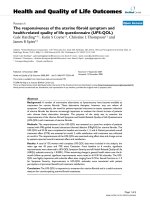
Figure 1 shows the comparison of computed in-cylinder pressure vs. crank angle diagram for gasoline
fueled engine with experimental one during power cycle at fuel-air equivalence ratio of 0.967, 1.084, and
1.173. The computed data closely follow the experimental data except in the vicinity of peak pressure.
Figure 2 shows more clearly the comparison of measured and computed peak pressures at different
equivalence ratio. The average difference is around 3%. The discrepancy of this peak pressure is caused
by the cycle to cycle dispersion, and is due to non-homogeneity of fuel mixture supply in the cylinder in
actual case, but theoretical calculations are based on constant homogeneous mixture supply at every
cycle. Great deals of experimental research work by Zerves Efthimis [36], Ceviz MA [37] have been
done on cyclic dispersion. Many authors [38, 39] suggested that the major source of cycle to cycle
variation is due to the variation in the spherical burning area, produced by variation in the position of the
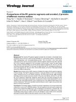
wall contact flame center and variation in the laminar flame speed at the spark center. In Figure 3, the
experimental and predicted results of NO and CO emission concentrations are compared with the
variation of fuel air equivalence ratio.
In Figure 4, the experimental indicated mean effective pressure and corresponding computational results
are compared with the variation of fuel-air equivalence ratio.
In Figure 5, the experimental results of cylinder pressure for CNG fueled engine are compared with the
present simulation model at the equivalence ratio(ER) of 0.7692. It shows that computed curve follows
the experimental pressure curves very closely.
Figure 6, compares the experimental Brake means effective pressures (BMEP) given by Aslam et al. [26]
for a CNG fueled engine and the theoretical ones calculated by using the present model. These figures
show that computational results are reasonably in good agreement with the measured one. The BMEP
maximizes at midrange of engine speed (≈ 3000 RPM). This is due to the friction which increases with
increasing engine speed. Another reason of BMEP loss is due to the longer ignition delay and low flame
speed of CNG fuel. These factors affect the Brake specific fuel consumption (BSFC). The figure shows
that BSFC drops as the engine speed increases in the low speed range and level off at medium speed
range and increases towards the high speed range. This is because of the heat losses to the combustion
chamber which proportionally increases with decrease in speed. On the other hand BSFC increases due
to the friction which increases with increase in engine speed.
It can be seen obviously from these comparisons that the present simulation model is capable to compute
accurately the engine performance of SI engine using gasoline or CNG fuel.
ISSN 2076-2895 (Print), ISSN 2076-2909 (Online) ©2010 International Energy & Environment Foundation. All rights reserved.
International Journal of Energy and Environment (IJEE), Volume 1, Issue 1, 2010, pp.31-52
37
Table 1. Technical data of engines for validation
Gasoline
Engine type (SI)
Cycle
Cylinder bore
Stroke
Connecting rod length
Compression ratio
Angle of ignition
Valve timing
evo
evc
ivo
ivc
Lower calorific value
Vauxhall Victor 2000cc (Baruah [34], Benson [2])
4 stroke
9.53cm
6.92cm
13.65cm
8.5
33.60 bTDC
114.60 aTDC
393.40 aTDC
326.60 aTDC
605.40 aTDC
44MJ/kg
CNG (Test Engine 1)
Engine type (SI)
Cycle
Cylinder bore
Stroke
Connecting rod length
Compression ratio
Angle of ignition
Lower calorific value
Proton Magma (Aslam [26])
4 stroke
7.55cm
8.2cm
13.65cm
9.2
40.00 bTDC
47.377MJ/kg
CNG (Test Engine 2)
Engine type (SI)
Cycle
Cylinder bore
Stroke
Connecting rod length
Compression ratio
Angle of ignition
Valve timing
evo
evc
ivo
ivc
Lower calorific value
Dongfeng Motor (Ma F [27])
4 stroke
10.5cm
12.0cm
19.2cm
10.5
30.00 bTDC
123.65 aTDC
371.65 aTDC
341.65 aTDC
577.65 aTDC
47.377MJ/kg
ISSN 2076-2895 (Print), ISSN 2076-2909 (Online) ©2010 International Energy & Environment Foundation. All rights reserved.
International Journal of Energy and Environment (IJEE), Volume 1, Issue 1, 2010, pp.31-52
38
60
Cylinder pressure (bar)
50
Gasoline
CR=8.5
WOT 3000 RPM
0
Spark advance 36.4 bTDC
XSP=0.3517
ER=0.967Comp
ER=0.967 Exp.
ER=1.084 Comp.
ER=1.084 Exp.
ER=1.173 Comp.
ER=1.173 Exp.
40
30
20
10
0
200
250
300
350
400
450
500
550
600
Crank angle (degree)
Figure1. Comparison of measured and computed cylinder pressure with crank angle at different
equivalence ratio
Maximum cylinder pressure (bar)
60
55
Gasoline
CR=8.5
WOT 3000 RPM
0
Spark advance 36.4 bTDC
XSP= 0.3517
Pmax Comp.
Pmax Exp.
50
45
40
35
30
0.7
0.8
0.9
1
1.1
1.2
1.3
1.4
Fuel-air equivalamce ratio
Figure 2. Comparison of measured and computed maximum cylinder pressure
ISSN 2076-2895 (Print), ISSN 2076-2909 (Online) ©2010 International Energy & Environment Foundation. All rights reserved.
International Journal of Energy and Environment (IJEE), Volume 1, Issue 1, 2010, pp.31-52
Gasoline
CR=8.5
cofac=0.5;WOT 3000 RPM
XSP=0.3517
Spark advance 36.40 bTDC
6000
10
9
8
7
4000
6
5
3000
4
2000
3
CO concentration (V%)
NO concentration (ppm)
5000
Comp. NO
Exp. NO
Comp. CO
Exp. CO
39
2
1000
1
0
0
0.7
0.8
0.9
1
1.1
1.2
1.3
1.4
Fuel air equivalance ratio
Figure 3. Comparison of measured and computed NO and CO concentration at different fuel-air
equivalence ratio
13
Gasoline
CR=8.5
XSP=0.3517; WOT 3000 RPM
Spark advance 36.40 bTDC
IMEP (bar)
12
EXP.
COMP.
11
10
9
8
0.7
0.8
0.9
1
1.1
1.2
1.3
1.4
Equivalence ratio
Figure 4. Comparison of computed and experimental IMEP with variation of equivalence ratio
ISSN 2076-2895 (Print), ISSN 2076-2909 (Online) ©2010 International Energy & Environment Foundation. All rights reserved.
International Journal of Energy and Environment (IJEE), Volume 1, Issue 1, 2010, pp.31-52
40
75
Cylinder pressure (bar)
60
27
CNG [ F.Ma ]
WOT;Eqiv.ratio=0.7692
CR=10.5,1200RPM
0
spark angle 30 bTDC
EXP.
COMP.
45
30
15
0
200
250
300
350
400
450
500
550
Crank angle (degree)
Figure 5. Comparison of computed and experimental cylinder pressure with crank angle
BMEP (MPa )
1
comp(BMEP)
exp(BMEP)
COMP(BSFC)
EXP(BSFC)
0.8
0.95
0.8
0.65
0.6
0.5
0.4
0.35
0.2
0
500
BSFC (kg/kWh)
1.2
CNG[ Aslam26]
WOT;Eqiv.ratio=0.943
CR=9.2
spark angle 360bTDC
1500
2500
3500
4500
5500
0.2
6500
Speed ( RPM )
Figure 6. Comparison of computed and experimental BMEP and BSFC with the variation of engine
speed
4. Results and discussion
Figure 7 shows the effect on in-cylinder pressure development with crank angle at different compression
ratio, at 3000 RPM wide open throttle and 360 bTDC spark timing. Figure illustrates that, with increase
in compression ratio peak pressure increases. This could be more clearly seen in Figure 8. This is
ISSN 2076-2895 (Print), ISSN 2076-2909 (Online) ©2010 International Energy & Environment Foundation. All rights reserved.
International Journal of Energy and Environment (IJEE), Volume 1, Issue 1, 2010, pp.31-52
41
because, the value of pressure and temperature of the mixture during sparking are higher at higher
compression ratios and heat release during combustion further increases the pressure and temperature to
the higher level. In the same time apparent flame speed increases and consequently combustion duration
decreases, this is shown in Figure 9.
The composition of the working mixture influences the rate of combustion and amount of heat evolved.
When the mixture is made leaner, it releases less thermal energy resulting in lower flame temperature
and hence flame speed reduces. With increase in compression ratio, the clearance volume decreases and
a greater portion of spent up gases are exhausted. This means, that there is less dilution of the charge and
charge density is greater during the burning process. In addition to this, the temperature of the charge is
high at higher compression ratio. Since the heat transfer increases with greater charge density and
increased temperature, the flame speed increases. At very lean air /fuel ratio, increasing compression
ratio results no significant change in flame speed. The combustion duration decreases with increase of
compression ratio, because the maximum cycle gas temperature increases resulting in higher apparent
flame speed. These factors greatly affect engine performance.
Figure 10 shows the effect of compression ratio on engine power, IMEP and BMEP, fuel consumption
and thermal efficiency. The increase in compression ratio shows the increase in mean effective pressure
and engine power, which is due to the higher cylinder gas pressure. The same figure also shows, as
compression ratio increases the specific fuel consumption decreases due to improved combustion with
higher peak pressure and temperature and due to more scope of expansion work.
Figure 11 shows the effect of compression ratio on CO and NO concentrations at exhaust-valve. It is
observed from the figure that as the compression ratio increases the concentrations of CO and NO
emission increase by increasing the maximum cycle temperature. In continuation, the effect of
compression ratio on CO and NO concentrations with fuel air equivalence ratio are shown in Figure 12.
In this figure equivalence ratio and spark timing are adjusted for maximum torque for BMEP data. This
also depicts that as compression ratio increases, the concentrations of NO and CO emission level
increase due to increase of cylinder temperature as shown in Figure 8.
It can be observed from Figure 10, higher the compression ratio higher is the indicated thermal
efficiency. The compression ratio is limited by two practical considerations, namely, material strength
and engine knock. Engine heads and blocks have a designed maximum stress, which should not be
exceeded, thus limiting the compression ratio. On the other hand, if maximum temperature exceeds the
auto-ignition temperature of air-fuel mixture, combustion will occur ahead of the flame, knock occurs
due to high rate of pressure rise causes damage to the engine.
Figure 13 shows the onset knock-limited compression ratio as a function of fuel-air equivalence ratio, for
two fuels with different octane number. The highest requirement is for slightly rich mixtures; increasing
richness and leanness, about this point decreases the octane requirement subsequently. Onset knock limit
depends on spark advance as shown in Figure 14: more advance sparking increases the peak pressure of
the cycle and therefore increases the pressure and temperature of the end charge resulting shortens delay
period (induction/auto ignition time) and increases the tendency to knock.
Figure 15 shows the onset knock-limited compression ratio as a function of equivalence ratio and
cylinder diameter. In this figure, XDS value is the ratio of cylinder diameter and fixed stroke length. The
tigure shows, initially onset knock limit decreases from 0.5 to 0.75 XDS and then increases with increase
in XDS value with increase in cylinder diameter. This is because high surface to volume ratio occurs for
smaller diameter engine, resulting in higher percentage of heat loss as shown in Figure 16.
The emission of carbon monoxide and nitric oxide also limits the use of higher compression ratio. The
concentrations of NO and CO emission depend upon compression ratio as well as spark plug location,
which is shown in Figures 17 and 18 respectively. Positioning of spark plug towards centre (XSP=0.125
to 0.5) and increasing compression ratio, NO and CO emission levels increase almost linearly in both the
conditions due to temperature increase inside the cylinder.
Figures 19 and 20 depict the effect of compression ratio and cylinder diameter to stroke length ratio
(XDS) on NO and CO emission levels at exhaust valve. These figures have been plotted for 0.9434
equivalence ratio, 3000 RPM engine speed and 360 bTDC spark timing. These figures illustrate that NO
and CO concentration levels increase by increasing XDS value and compression ratio. XDS is the ratio
of cylinder diameter and stroke length, where cylinder diameter is changed and stroke length is kept
constant. Smaller the value of XDS means smaller cylinder diameter, high surface to volume ratio,
resulting in higher percentage of heat loss as shown in Figure 16. Thus low temperature inside the
cylinder implies low emission of NO and CO concentrations.
ISSN 2076-2895 (Print), ISSN 2076-2909 (Online) ©2010 International Energy & Environment Foundation. All rights reserved.
International Journal of Energy and Environment (IJEE), Volume 1, Issue 1, 2010, pp.31-52
42
80
Cylinder pressure (bar)
CR=8
CR=9
CR=9.2
CR=10
CR=11
CR=12
CNG
WOT;Eqiv.ratio=0.943
3000 RPM
0
spark angle 36 bTDC
70
60
50
40
30
20
TDC
10
0
240
280
320
360
400
440
480
520
Crank angle (degee)
Figure 7. Variation of in-cylinder pressure with crank angle at different compression ratio
2800
2760
70
60
2720
50
2680
40
30
2640
20
Max. cylinder temperature (K)
80
Max.cylinder pressure (bar)
Pmax
Tmax
CNG
WOT;Eqiv.ratio=0.943
3000 RPM;
0
spark angle 36 bTDC
90
2600
10
0
2560
6
7
8
9
10
11
12
13
14
Compression ratio
Figure 8. Variation of maximum cylinder pressure and temperature with compression ratio
ISSN 2076-2895 (Print), ISSN 2076-2909 (Online) ©2010 International Energy & Environment Foundation. All rights reserved.
International Journal of Energy and Environment (IJEE), Volume 1, Issue 1, 2010, pp.31-52
CNG
WOT;Eqiv.ratio=0.943
3000 RPM
0
spark angle 36 bTDC
Combustion duration
Apparent flame speed
16.8
16.5
63.5
16.2
63
15.9
62.5
15.6
62
15.3
61.5
15
61
Apparent flame speed (m)
Combustion duration(degree)
64
43
14.7
6
7
8
9
10
11
12
13
14
Compression ratio
Figure 9. Variation of combustion duration and apparent flame speed at different compression
ratio
IMEP(bar)
IP(kW)
ITE(%)
BSFC(kg/kWh)
CNG
WOT;Eqiv.ratio=0.943
3000 RPM
0.29
0
spark angle 36 bTDC
35
0.27
30
0.25
25
0.23
20
0.21
15
0.19
10
0.17
5
0.15
6
7
8
9
10
11
12
13
ISFC (kg/kWh), BSFC (kg/kWh)
IMEP(bar),BMEP(bar),IP(kW),
BP(kW),ITE(%)
40
BMEP(bar)
BP (kW)
ISFC(kg/kWh)
14
Compression ratio
Figure 10. Engine performances vs. compression ratio
ISSN 2076-2895 (Print), ISSN 2076-2909 (Online) ©2010 International Energy & Environment Foundation. All rights reserved.
International Journal of Energy and Environment (IJEE), Volume 1, Issue 1, 2010, pp.31-52
5000
4500
NO concentration (ppm)
NO
CO
CNG
WOT;Eqiv.ratio=0.943
3000 RPM
0.5
0
spark angle 36 bTDC
0.46
4000
0.42
3500
0.38
3000
2500
0.34
2000
0.3
6
7
8
9
10
11
12
13
CO concentration (%V)
44
14
Compression ratio
Figure 11. Variation of NO and CO concentration with compression ratio variation
10.0 CR
12.0 CR
9.2 CR
11.0CR
14.0 CR
5
4.5
NO concentration (ppm)
3000
4
2500
3.5
3
2000
2.5
1500
2
1.5
1000
1
500
CO concentration (V%)
3500
9.2 CR
11.0CR
14.0 CR
10.0 CR
12.0 CR
CNG
Wide open throttle
3000 RPM
0.5
0
0
0.7
0.8
0.9
1
1.1
1.2
1.3
Fuel-air equivalence ratio
Figure 12. Variation of NO and CO concentration vs. equivalence ratio at different CR with MBT
condition
ISSN 2076-2895 (Print), ISSN 2076-2909 (Online) ©2010 International Energy & Environment Foundation. All rights reserved.
International Journal of Energy and Environment (IJEE), Volume 1, Issue 1, 2010, pp.31-52
15
CNG
WOT; 3000 RPM
Eqiv.ratio=0.943
0
spark angle 36 bTDC
14
45
120-ON
130-ON
Compression ratio
13
12
11
10
9
8
7
0.5
0.6
0.7
0.8
0.9
1
1.1
1.2
1.3
1.4
Fuel-air equivalence ratio.
Figure 13. Knock limits as function of compression ratio and fuel-air equivalence ratio
CNG
WOT 3000 RPM
XSP=0.3517
ON=130
Spark advance angle (degree)
40 bTDC
30 bTDC
26 bTDC
36 bTDC
22
Compression ratio
20
18
16
14
12
10
8
0.6
0.8
1
1.2
1.4
Equivalence ratio
Figure 14. Variation of onset knock limit with equivalence ratio and spark advance
ISSN 2076-2895 (Print), ISSN 2076-2909 (Online) ©2010 International Energy & Environment Foundation. All rights reserved.
International Journal of Energy and Environment (IJEE), Volume 1, Issue 1, 2010, pp.31-52
46
CNG
WOT 3000 RPM
0
spark angle 36 bTDC
ON=130
16
XDS=0.5
XDS=0.75
XDS=1.0
XDS=1.2
15
XDS=0.9207
Compression ratio
14
13
12
11
10
9
8
7
0.6
0.7
0.8
0.9
1
1.1
1.2
1.3
1.4
Equivalence ratio
Figure 15. Variation of onset knock limit with equivalence ratio and the value of XDS (diameter/stroke)
XDS=0.5
XDS=0.7
XDS=1.0
XDS=0.9207
CNG
WOT;Eqiv.ratio=0.943
3000 RPM
0
spark angle 36 bTDC
35
XDS=0.6
XDS=0.8
XDS=1.1
Heat loss (%)
30
25
20
15
10
7
8
9
10
11
12
13
Compression ratio
Figure 16. Variation of percentage heat loss during power cycle with compression ratio at different value
of XDS
ISSN 2076-2895 (Print), ISSN 2076-2909 (Online) ©2010 International Energy & Environment Foundation. All rights reserved.
International Journal of Energy and Environment (IJEE), Volume 1, Issue 1, 2010, pp.31-52
CNG
WOT;Eqiv.ratio=0.943
3000 RPM
0
spark angle 36 bTDC
7000
NO concentration (ppm)
6000
47
XSP=0.125
XSP=0.250
XSP=0.375
XSP=0.5
5000
4000
3000
2000
1000
0
7
8
9
10
11
12
13
Compression ratio
Figure 17. Variation of NO concentration with compression ratio at different spark plug location
CNG
WOT;Eqiv.ratio=0.943
3000 RPM
0
spark angle 36 bTDC
0.55
XSP=0.125
XSP=0.250
XSP=0.375
XSP=0.5
CO concentration (%V)
0.5
0.45
0.4
0.35
0.3
0.25
7
8
9
10
11
12
13
Compression ratio
Figure 18. Variation of CO concentration with compression ratio at different spark plug location
ISSN 2076-2895 (Print), ISSN 2076-2909 (Online) ©2010 International Energy & Environment Foundation. All rights reserved.
International Journal of Energy and Environment (IJEE), Volume 1, Issue 1, 2010, pp.31-52
48
6000
NO concentration (ppm)
XDS=0.5
XDS=0.7
XDS=1.0
XDS=0.9207
CNG
WOT;Eqiv.ratio=0.943
3000 RPM
0
spark angle 36 bTDC
XDS=0.6
XDS=0.8
XDS=1.1
5000
4000
3000
2000
1000
0
7
8
9
10
11
12
13
Compression ratio
Figure 19. Variation of NO concentration with compression ratio at different value of XDS (diameter
/stroke)
CNG
WOT;Eqiv.ratio=0.943
3000 RPM
0
spark angle 36 bTDC
0.5
XDS=0.5
XDS=0.7
XDS=1.0
XDS=0.9207
XDS=0.6
XDS=0.8
XDS=1.1
CO concentration (V%)
0.45
0.4
0.35
0.3
0.25
0.2
0.15
0.1
7
8
9
10
11
12
13
Compression ratio
Figure 20. Variation of CO concentration with compression ratio at different value of XDS
(diameter/stroke)
ISSN 2076-2895 (Print), ISSN 2076-2909 (Online) ©2010 International Energy & Environment Foundation. All rights reserved.
International Journal of Energy and Environment (IJEE), Volume 1, Issue 1, 2010, pp.31-52
49
5. Conclusion
A general engine simulation GENSIM technique has been developed to model power cycle interfaced
with gas dynamic effect of intake and exhaust manifolds of four-cylinder spark ignition engines.
Comparisons between theoretical results obtained from the present computer simulation model and
experimental results have been made to confirm for the reliability and accuracy of the present model for
predicting performance of SI engine running on gasoline and CNG fuel.
The following conclusions are drawn from the present analytical diagnostics:
1. The CNG fueled SI engine is most efficient when running on stoichiometric or slightly lean
(Ø=0.9-1.0) mixture at moderate engine speed (≈ 3000 RPM) and MBT spark timing.
2. Brake power, indicated power and thermal efficiency increase with the increase of compression
ratio.
3. The CO emission increases towards rich mixture. NO concentration varies with fuel conditions
as it increases at slightly lean stoichiometric mixture (Ø ≈0.9Ø) and reduces toward leaner and
richer mixture.
4. The highest requirement of knock limit compression ratio is for slightly rich mixture (Ø=1-1.15),
increasing richness on leanness decreases the octane requirement subsequently.
5. Onset knock limit depends on spark advance. An increase in spark advance from the optimized
timing increases the tendency to knock, thus retarding has low tendency to knock.
6. It is observed that retarding timing helps to reduce NOx and knock. Thus retarding timing is
preferable from the MBT timing, although some power is lost.
7. Onset knock limit depends upon cylinder bore- to- stroke ratio. Onset knocks decreases from 0.5
to 0.75 XDS and then increases with increase in XDS value.
References
[1] J.B. Heywood. International combustion engine fundamental. McGraw-Hill, (1988).
[2] J.H. Horlock, D.E. Winterbone - Benson Rowland S. Thermodynamics and gas dynamics of
Internal Combustion engine. New York: Clarendon Press Oxford (1986) Vol. II.
[3] C.R. Ferguson and A.T. Kirkpatrick. Internal combustion engines. Second Edition, John Wiley
and Sons, Inc. New York (2001).
[4] H.N. Gupta and G. Prasad. Performance and emission prediction for a natural gas fueled sparkignition engine. Proceedings of the XVI national conference on IC engines and combustion. Jan
20-22, (2000) pp. 230-235.
[5] Maher A.R. Sadiq Al-Baghdadi, Haroun A.K. Shahad. Improvement of performance and reduction
of pollutant emission of a four stroke spark ignition engine fueled with hydrogen-gasoline fuel
mixture. Energy Conversion and Management 41 (2000) 77-91.
[6] Maher A.R. Sadiq Al-Baghdadi. A simulation model for a single cylinder four- stroke spark
ignition engine fueled with alternative fuels. Turkish J. Eng. Env. Sci. 30 (2006) 331-350.
[7] J.V. Tirkey, H.N. Gupta, S.K. Shukla. Integrated Gas Dynamic and Thermodynamic
Computational Modeling of Multicylinder 4-stroke SI engine using Gasoline as a fuel.
Proceedings of 2008 ASME Summer Heat Transfer Conference HT2008, August 10-14,
Jacksonville, Florida USA, (2008).
[8] J.V. Tirkey, H.N. Gupta. Computer simulation and combustion diagnostic of multi cylinder 4stroke SI engine using CNG as a fuel. International Journal of Applied Engineering Research
(2008) Vol.3, No.5, pp. 667-680.
[9] A. Agarwal and D.N. Assanis. Multi-Dimensional Modeling of Natural Gas Ignition under
Compression Ignition Conditions Using Detailed Chemistry. SAE 980136, (1998).
[10] A. Agarwal, D. Assanis. Multi- Dimensional Modeling of Ignition, Combustion and Nitric Oxide
Formation in Direct Injection Natural Gas Engines. SAE 2000-01-1839.
[11] R. Miller, G. Davis et al. A Super-Extended Zel’dovich Mechanism for NOX Modeling and
Engine Calibration. SAE 980781, (1998).
[12] E. Sher and T. Bar-Kohany. Optimization of variable valve timing for maximizing performance of
an unthrottled SI engine-a theoretical study. Energy 27 (2002) 757-775.
[13] Stephen R Turns. An Introduction to Combustion. 2nd ed. Singapore: McGraw-Hill; (2000).
[14] M.D. Checkel and J.D. Dale. Computerized knock detection from engine pressure records. SAE,
860028, (1986).
ISSN 2076-2895 (Print), ISSN 2076-2909 (Online) ©2010 International Energy & Environment Foundation. All rights reserved.
50
International Journal of Energy and Environment (IJEE), Volume 1, Issue 1, 2010, pp.31-52
[15] K.M. Chun, J.B. Heywood. Characterization of knock in a spark ignition engine. SAE 890156,
(1989).
[16] E. Moses, A.L. Yarin and P. Bar-Yoseph. On knocking prediction in spark ignition engines.
Combustion and Flame 101: 239-261 (1995).
[17] A. By, B. Kempinski and J.M. Rife. Knock in spark ignition engines. SAE 810147, (1981).
[18] G. K?nig and C.G.W. Sheppard. End gas auto ignition phenomenon in internal combustion engine.
SAE 902135, (1990).
[19] Soylu, J.V. Gerpen. Development of an auto ignition sub model for natural gas engines. Fuel
82(2003) 1699-1707.
[20] M.A. Liberman, M.F. Ivanov, O.E. Peil, D.M. Valiev and L.E. Eriksson. Numerical Modeling of
the Propagating Flame and Knock Occurrence in Spark-Ignition Engines. Combust. Sci. and Tech.,
177: 151-182, 2005.
[21] J.C. Livengood and P.C. Wu. Correlation of auto ignition phenomenon in internal combustion
engine and rapid compression machines. Fifth symposium (International) on combustion, pp 347356, 1955.
[22] A.M. Douaud and P. Eyzat. Four-octane number method for predicting the anti-knock behavior of
fuels and engine. SAE 780080, 1978.
[23] C. Elmqvist, F. Lindstr?m and H.E. ?ngstr?m, B. Grandin, G. Kalghatgi. Optimizing Engine
Concepts by Using a Simple Model for Knock Prediction. SAE 2003-01-3123.
[24] J.W.G. Turner et al. Performance and fuel economy enhancement of pressure charged SI engines
through turboexpansion-An initial study. SAE 2003-01-0401.
[25] Seref Soylu. Prediction of knock limited operating conditions of a natural gas engine. Energy
Conversion and Management 46 (2005) 121-138.
[26] M.U. Aslam, H.H. Masjuki et al. An experimental investigation of CNG as an alternative fuel for a
retrofitted gasoline vehicle. Fuel 85 (2006) 717-724.
[27] Fanhua Ma, Yu Wang, Liu Haiquan, Y. Li, J. Wang, S. Zhao. Experimental study on thermal
efficiency and emission characteristics of a lean burn hydrogen enriched natural gas engine.
International Journal of Hydrogen Energy 32 (2007) 5067-5075.
[28] Rowland S. Benson. (Edited by Horlock JH, Winterbone DE) Thermodynamics and gas dynamics
of Internal Combustion engine. New York: Clarendon Press Oxford 1982 Vol. I.
[29] W.J.D. Annand. Heat transfer in the cylinders of reciprocating internal combustion engine. Proc.
Inst. Mech. Engrs. Vol.177, 973-990, (1963).
[30] A.N. Lipatnikov, J. Chomiak. Turbulent flame speed and thickness: phenomenology, evaluation,
and application in multi-dimensional simulations. Progress in energy and combustion science 28
(2002) 1-74.
[31] S. Verhelst. and R. Sierens. A quasi-dimensional model for the power cycle of a hydrogen fueled
ICE. International Journal of Hydrogen Energy 32 (2007) 3545-3554.
[32] S.Y. Liao, D.M. Jiang and Q. Cheng. Determination of laminar burning velocities for natural gas.
Fuel 83(2004) 1247-1250.
[33] H.W. Branes-Moss. A designer’s viewpoint, in passenger car engine. Conference Proceedings,
Institution of Mechanical Engineers, London, 1975, pp. 133-47.
[34] G.H. Abd Alla. Computer simulation of a four stroke spark ignition engine. Energy Conversion
and Management 43 (2002) 1043-1061.
[35] P.C. Baruah, R.S. Benson and H.N. Gupta. Performance and emission predictions for a multicylinder spark ignition engine with catalytic converter. SAE 780672, 1978.
[36] E. Zervas. Correlation between cycle-to-cycle variations and combustion parameters of a spark
ignition engine. Applied Thermal Engineering. Vol. 24(2004) 2073-2081.
[37] M.A. Ceviz and F. Yüksel, Cyclic variation on LPG and Gasoline-fueled lean burn SI engine.
Renewable Energy 31(2006) 1950-1960.
[38] J.C. Keck, J.B. Heywood, G. Noske. Early flame development and burning rates in spark ignition
engines and their cyclic variability. SAE 870164, 1987.
[39] G.T. Kalghatgi. Spark ignition, Early flame development and cyclic variation in IC-Engines. SAE
870163, 1987.
ISSN 2076-2895 (Print), ISSN 2076-2909 (Online) ©2010 International Energy & Environment Foundation. All rights reserved.