Hệ thống thủy lực máy đào CATERPILLAR SERIE D - P3
Bạn đang xem bản rút gọn của tài liệu. Xem và tải ngay bản đầy đủ của tài liệu tại đây (1.15 MB, 48 trang )
SERV1852-02
August 2008
GLOBAL SERVICE LEARNING
TECHNICAL PRESENTATION
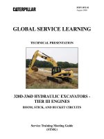
320D -336D HYDRAULIC EXCAVATORS TIER III ENGINES
INTRODUCTION
Service Training Meeting Guide
(STMG)
320D -336D HYDRAULIC EXCAVATORS TIER III ENGINES
INTRODUCTION ((320D - 336D)
AUDIENCE
Level II - Service personnel who understand the principles of machine systems operation,
diagnostic equipment, and procedures for testing and adjusting.
CONTENT
This presentation provides an introduction and machine walkaround for the 320D-336D
Hydraulic Excavator. Additional presentations will cover the engines, pilot system, pumps and
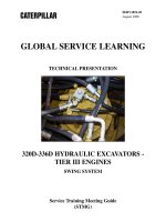
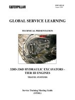
controls, main control valve group, swing system, travel system, and tool control systems in
more detail. This presentation may be used for self-paced and self-directed training.
OBJECTIVES
After learning the information in this presentation, the technician will be able to:
1. identify the major components and controls of a 320D-336D Hydraulic Excavator, and
2. perform a machine walkaround inspection and daily maintenance.
REFERENCES
320D Hydraulic Excavator Specalog
323D L and 323D LN Hydraulic Excavators
324D Hydraulic Excavator Specalog
325D Hydraulic Excavator Specalog
328D Hydraulic Excavator Specalog
330D Hydraulic Excavator Specalog
Machine Monitoring System - Systems Operation
Self-study "300D Series Hydraulic Excavators, 345C Hydraulic Excavator,
and 365C & 385C Large Hydraulic Excavators
iTIM " '300C' Series Hydraulic Excavators-Electronic Control Systems"
iTIM "325C Hydraulic Excavators-Hydraulic Systems"
325D Hydraulic Schematic
Estimated Time: 1 Hour
Illustrations: 41
Form: SERV1852-02
Date: August 2008
© 2008 Caterpillar
AEHQ5856
HEHH3327
AEHQ5663
AEHQ5665
AEHQ5706
AEHQ5667
RENR8068
SERV7032
SERV2693
SERV2701
KENR6157
SERV1852-02
08/08
-3-
Text Reference
Introduction
TABLE OF CONTENTS
INTRODUCTION ........................................................................................................................5
MACHINE WALK-AROUND...................................................................................................14
325D Hydraulic Excavator ...................................................................................................16
330D Hydraulic Excavator ...................................................................................................25
OPERATOR STATION ..............................................................................................................33
CONCLUSION...........................................................................................................................48
SERV1852-02
08/08
-4-
Text Reference
Introduction
PREREQUISITES
"Fundamentals of Mobile Hydraulics Self Study Course"
"Fundamentals of Power Train Self Study Course"
"Fundamentals of Electrical Systems Self Study Course"
"Fundamentals of Engines Self Study Course"
TEMV3002
TEMV3003
TEMV3004
TEMV3001
NOTES
Nomenclature Change: During the fourth quarter of 2008, the 325D and 330D
nomenclature changed. The 325D became the 329D and the 330D became the 336D for
most arrangements.
The exceptions are as follows:
- The nomenclature for the 325D MH and 330D MH did not change.
- The nomenclature for the 325D FM and 330D FM did not change.
- The 325D HD HW did not change into 329D HD HW. This model is being discontinued.
However, the 330D HD HW changed to the 336D HD HW.
SERV1852-02
08/08
-5-
Text Reference
Introduction
320D-336D EXCAVATORS - TIER III ENGINES
INTRODUCTION AND SYSTEMS OPERATION
(320D - 330D)
© 2008 Caterpillar
1
INTRODUCTION
The Caterpillar 320D-336D range of Hydraulic Excavators incorporate design innovations and
performance improvements from the 300C Hydraulic Excavator Series and are a direct
replacement for them.
The range comprises of: 320D, 321D, 323D, 324D, 325D, 328D, & 330D, with some models
having various additional machine arrangements. During the fourth quarter of of 2008, the
329D replaced the 325D and the 336D replaced the 330D for most arrangements.
The machines feature a new cab for greater operator comfort. The cab provides the operator
with excellent visibility of processing equipment, trucks, and railcars. The cab, consoles, and
joysticks have been improved to provide a better access and understanding of all functions.
This presentation discusses the systems operation of the 320D-336D Hydraulic Excavators,
along with basic engine and machine component location.
NOTE: Most of the illustrations of the iron in this presentation will be of the 325D and
330D excavators. The other models will be configured similarly, but component
locations may be different. Some of the illustrations may show pilot iron instead of
production iron.
The most significant differences will be related to the engine compartment due to the
three different engines being used in this series of machines as well as two of the models
being compact radius (CR).
SERV1852-02
08/08
-6-
Text Reference
Introduction
300D SERIES HYDRAULIC EXCAVATORS
Model Engine
Configurations Available
320D
C6.4
L, LN, FM, MH, RR, L RR, LL
321D
C6.4
CR, LCR
323D
C6.4
L, LN, S, SA
324D
C7
L, LN, FM
325D/329D
C7
L, LN, FM, MH, L MH, UHD, L HW, L HD
328D
C7
LCR
330D/336D
C9
L, LN, FM, MH, WH, L HD, L RE, U HD, L HW
During the fourth quarter of 2008, the 325D became the 300D and the 330D became the 336D for most machine configurations.
The 325D MH and 330D MH did not change. The 325D FM and 330D FM did not change. The 325D HD HW was discontinued.
2
The 320D-336D Hydraulic Excavators cover the 20 to 36 metric ton class of excavators and are
extremely versatile machines capable of performing a wide range of tasks by utilizing the
various work tools available. For the "D" Series models shown, they are all equipped with
ACERTTM Tier III engines.
NOTE: Some of the "D" Series excavators arrangements are built using Tier II engines
to better meet market needs in certain parts of the world.
The machines can be configured with a wide range of undercarriages including standard, long
(L) and long and narrow width (LN).
For some models additional letters are included in the nomenclature, for example: forest
machine (FM), material handler (MH), heavy duty (HD), and waste handling (WH) to designate
the machine application.
The 321D and 328D are only available as compact radius (CR) machines.
As mentioned, during the fourth quarter of 2008, the 325D and 330D nomenclature changed to
the 329D and 336D respectively.
The reason for the change was to better align the machine nomenclature with the actual
machine weight. Making this change should lead to increased machine sales.
SERV1852-02
08/08
-7-
Text Reference
Introduction
The exceptions to this nomenclature change are as follows:
- The nomenclature for the 325D MH and 330D MH did not change.
- The nomenclature for the 325D FM and 330D FM also did not change.
- The 325D HD HW did not change into 329D HD HW. This model is being discontinued.
However, the 330D HD HW changed to the 336D HD HW.
SERV1852-02
08/08
-8-
Text Reference
Introduction
3
4
The 320D, 325D, and 330D can be configured as a material handler (MH). A fixed cab riser, or
as shown here, a hydraulic cab riser is available.
The cab riser provides different operating heights with excellent visibility for loading and
unloading processing equipment, trucks, and rail cars.
The 321D CR and 328D LCR are compact radius (CR) machines. With CR machines, the
machine tailswing is within the width of the undercarriage (depending on track width).
SERV1852-02
08/08
-9-
Text Reference
Introduction
SIMILARITIES AND DIFFERENCES
FEATURES
DIFFERENT
Machine Appearance
SIMILAR
X
Operator s Station
X
Engine
X
Implement Hydraulic System
Monitoring System
SAME
X
X
Maintenance Items
X
Tool Control Systems
X
Machine ECM
X
Travel System
X
Undercarriage
X
5
This chart displays some the similarities and differences between the 300D Series and the 300C
Series hydraulic excavators. New and improved features include:
Operator's Station: The layout of the interior has been redesigned to maximize operator
comfort and reduce operator fatigue. Frequently used switches have been relocated for easier
access.
The consoles and armrests have been redesigned for better comfort and adjustability. More seat
options are available: the standard mechanical suspension seat, or the optional air suspension
seat with heater.
Engine: The "D" Series machines are equipped with Tier III ACERTTM engines. The C6.4
engine is used in the 320D, 321D, and 323D. The C7 engine is used in the 324D, 325D/329D,
and the 328D. The C9 engine is used in the 330D/336D.
Monitor: The monitor is a full color Liquid Crystal Display that provides vital operating and
performance information, which is all in a simple, easy to navigate format.
Tool Control: The tool control systems for the 300D are similar in function as the tool control
systems for the 320C - 330C medium excavators, although the medium pressure circuit is now
a stand-alone function.
SERV1852-02
08/08
- 10 -
Text Reference
Introduction
The SmartBoom™ attachment enhances operation of the boom function and significantly
reduces cycle times of the machine. The SmartBoom™ is essentially a boom float attachment,
which allows the operator to lower the boom under its own weight or for the boom to raise up
due to stick force.
Service and maintenance intervals have been extended to reduce machine service time and
increase machine availability.
Options include the following:
The Machine Security System (MSS): This system uses a special Caterpillar key with
an embedded electronic chip for controlling unauthorized machine operation.
Product Link: This option provides all kinds of information and working parameters
through a satellite connection between an on-board computer and the machine. Product
Link provides easier fleet management and improved preventive maintenance. PL121
and PL321 are both available.
AccuGrade: This option provides precise control of the work tool using special
software.
Auxiliary Hydraulic Options: This option allows the machine to be configured to meet
the work tool needs, while increasing its versatility.
- Single Function Circuit is suited for tools that require one-way flow with one or both
pumps, such as hammers and vibratory plate compactors.
- Double Function Circuit is suited for tools that require two-way flow, utilizing one or
two pump flows, such as thumbs, non-rotation grapples, or shears.
SERV1852-02
08/08
- 11 -
Text Reference
Introduction
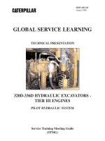
MAIN HYDRAULIC SYSTEM
Stick Cylinder
Bucket Cylinder
Swing Motor
Main Control Valve Group
Pilot
Control
Valves
Priority
Valves
Pilot Manifold
Pilot
Pump
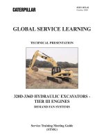
Fan
Motor
Boom Cylinders
Travel Motors
Main
Hydraulic
Pumps
M
Fan
Pump
Tank
The Fan Motor and Pump are only Used on the 330D and 336D
6
For the most part the main implement hydraulic system operation for the 320D-336D is the
same as the 300C Series. The "D" Series continues using many of the "C "excavator features,
such as automatic priorities and tool control systems.
The machines use a negative flow (NFC) hydraulic system. The main control valve group and
pumps are similar to the "C" Series. Each of the models may have the components located in
different locations due to the size of the machine or the type of carbody.
The 330D/336D is equipped with a new main hydraulic pump design and is the only model
equipped with a hydraulic demand fan system.
The smaller machines can be equipped with an optional visconic demand fan if needed for
working in areas with high ambient temperatures.
SERV1852-02
08/08
- 12 -
Text Reference
Introduction
7
The optional tool control system maximizes work tool productivity by configuring hydraulic
flow, pressure, and operator controls to match a specific work tool. System versatility enables a
wide range of tools to be used.
The system stores pressure and flow information for up to ten tools. Selectable Cat tools have
preset flows and pressures.
The 300D excavators produced in Akashi and Aurora (for the North American Commercial
Division (NACD) can be equipped with the following factory installed tool control systems:
- System 3 (Hammer) - provides two pump flow in a single direction only. This system
also includes a mechanical line relief valve for tools requiring lower pressure settings
(single action).
- System 5 (Thumb) - provides one pump flow in both directions (extend/retract double
action) and can be controlled with a foot pedal or a joystick.
- System 14 (Multifunction) - provides one or two pump flow in one or two directions
(single action or double action). System 14 has full electronic controls. An optional,
independent medium pressure circuit is used for such applications as a rotating shear or
ditch cleaning bucket.
The System 14 functions are now controlled through the Machine ECM. A separate Tool
Control ECM as was used on the 300C Series is not needed.
SERV1852-02
08/08
- 13 -
Text Reference
Introduction
The machines produced in Akashi and Gosselies for the EAME market will have the following
factory installed optional tool control systems:
- System 16 - provides two pump flow in a single direction, has a direct return system to
the hydraulic tank, and includes a mechanical for tools requiring lower pressure settings
(single action).
- System 17 (Multifunction) - provides one or two pump flow in one or two directions
(single action or double action). System 17 has a direct return system to the hydraulic
tank, instead of the oil returning through the main control valve group. System 17 has
full electronic controls.
An independent medium pressure circuit is available with System 17 to use for
applications such as a rotating shear or a ditch cleaning bucket.
SERV1852-02
08/08
- 14 -
1
2
3
Text Reference
Introduction
4
5
6
7
8
MACHINE WALK-AROUND
The 300D Series track excavators have been designed for fast, easy service with extended
service intervals, advanced filtration, convenient filter access, and user-friendly electronic
diagnostics for increased productivity and reduced maintenance costs.
The hydraulic system and component locations have been designed to provide a high level of
system efficiency. The main pumps, control valves, and hydraulic tank are located close
together to allow for shorter tubes and lines between components which reduces friction loss
and pressure drops in the lines. This design reduces engine compartment heat and sound being
transmitted to the operator.
Components shown include:
- stick (1)
- boom (2)
- operator station (3)
- access door to air cleaner and battery compartment (4)
- engine access cover (5)
- access door to radiator compartment (6)
- counterweight (7)
SERV1852-02
08/08
- 15 -
Text Reference
Introduction
9
This illustration shows the major components and service areas on the machine.
NOTE: The 325D and 330D will be used on the following pages to show components
and their locations on the 300D Series excavators. These locations may vary between
the other models.
The locations and components used on the 320D, 321D, 323D, 324D and 328D will be
more similar to the 325D/329D than the 330D/336D.
SERV1852-02
08/08
- 16 -
1
2
Text Reference
Introduction
3
4
5
10
325D/329D Hydraulic Excavator
This illustration shows access to the top of the machine from the right side.
The engine access cover (1) allows access to the engine from the top of the machine.
The machine hydraulic oil tank (2) is located between the pump compartment and the diesel
fuel tank on the right side of the machine and is accessed from the top of the machine.
The diesel fuel filler cap (3) is accessed from the top of the machine.
The storage compartment (4) is located in the front of the machine.
The step and hand rail (5) at the right front of the machine can be used for access to the top of
the machine.
SERV1852-02
08/08
- 17 -
Text Reference
Introduction
2
4
1
5
3
6
11
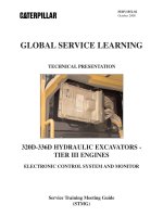
The compartment behind the operator station includes the following components:
- Machine ECM (1)
- air conditioning condenser and receiver (2)
- master disconnect switch and circuit breakers (3)
- dual element, radial seal air filter (4)
- batteries (5)
- engine shutoff switch (6) (on machines with a cab riser)
The Machine ECM also includes software for the Tool Control System.
NOTE: The machine used in this illustration is equipped with a cab riser. On most
machines a window washer solvent reservoir would be shown behind the master
disconnect switch and circuit breakers.
SERV1852-02
08/08
- 18 -
Text Reference
Introduction
1
2
6
3
8
10
4
9
5
7
12
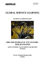
The radiator access compartment is located in front of the counterweight. The door is hinged
on the right and has a locking latch on the left side to keep it closed. This door provides access
to assist in cleaning some of the cooling system components:
- Air to Air After Cooler (ATAAC) (1)
- manual cab lowering valve (2) (only for machines with cab risers)
- hydraulic oil cooler (3)
- fuel priming pump (4) (will be changed to electric priming pump)
- fuel filter (5)
- fuel sensors (6) (temperature and pressure)
- fuel water separator (7)
- engine coolant overflow bottle (8)
- radiator (located behind the water separator and coolant overflow bottle) (9)
- left compartment release lever (access to batteries and air filter) (10)
- joystick pattern change valve (not shown) is located on compartment floor
SERV1852-02
08/08
- 19 -
Text Reference
Introduction
8
7
2
1
5
6
4
3
10
9
13
The illustration shows the pump compartment on the right side of the machine. The
compartment is accessed from the right side of the machine when the rear access door is open.
Some of the visible components are:
- engine oil filter (1)
- pilot pump (2)
- medium pressure circuit pump (3)
- drive pump (4)
- idler pump (5)
- pilot filter (6)
- case drain filter (7)
- hydraulic system return oil filter (8)
- pressure taps for auxiliary tool solenoids (9)
- solenoids for the medium pressure circuits (10)
SERV1852-02
08/08
- 20 -
Text Reference
Introduction
1
2
3
4
14
The 320D-336D pilot manifold is the same as the 300C Series pilot manifold. The pilot
manifold is accessible by removing the cover plate under the machine, behind the swing
bearing. The manifold is located directly below the main control valve. Pilot manifold
components visible are:
- two-speed travel solenoid (1)
- swing brake solenoid (2)
- hydraulic activation valve (3)
- hydraulic activation solenoid (4)