Lời giải chương 10 Digital System Projects Using HDL bộ môn hệ thống số
Bạn đang xem bản rút gọn của tài liệu. Xem và tải ngay bản đầy đủ của tài liệu tại đây (283.32 KB, 19 trang )
Instructor's Resource Manual – Digital Systems Principles and Applications - 11th edition
___________________________________________________________________________________________________
CHAPTER TEN - Digital System Projects Using HDL
10.1
(a) This project is a security system that monitors the open/closed status of a number of
doors in the building. The status of each door must be monitored in a remote security shack.
When any door is securely closed, the corresponding LED in the guard's shack should be off.
When the door is open, the corresponding LED should blink. Specifications for this system:
Number of doors: 8
Number of LED indicators: 8
Blink rate: 2.5 Hz
Door sensors: Door open/contacts open, door closed/contacts closed.
(b) Three major blocks:
MUX
Timing and control (counter)
DEMUX
(c) Block interconnections:
MUX
INPUTS:
OUTPUT:
8 door sensors (HIGH = OPEN, LOW = CLOSED)
3 binary select lines
1 serial data line
Timing
INPUTS:
OUTPUTS:
Clock
3 binary select lines counting 0-7
DEMUX
INPUTS:
3 binary select lines
1 serial data line
8 LED drivers (active LOW)
OUTPUTS:
(d) 20 Hz
(e) Only one LED will ever be lit at any time.
10.2
24 steps
10.3
4 states = 4 steps x 15º/step = 60º of rotation.
10.4
8 states = 8 steps x 7.5º/step = 60º of rotation.
10.5
3 state transitions x 15º/step = 45º of rotation.
10.6
Connect a de-bounced push button switch to the step input, a toggle switch to the dir input,
two toggle switches to the mode (m1, m0) inputs, and four LEDs to the outputs cout.
a.
b.
c.
set m1, m0 to [0,0] and dir to 0. Apply pulses to step and compare the LED states to Table 10-1 Full
step mode. Repeat with dir=1.
set m1, m0 to [0,1] and dir to 0. Apply pulses to step and compare the LED states to Table 10-1 Wave
drive mode.
set m1, m0 to [1,01] and dir to 0. Apply pulses to step and compare the LED states to Table 10-1 Half
step mode.
Set m1, m0 to [1,1]. Connect toggle switches to each of the inputs Cin[3..0]. Using a logic
probe, monitor each cout line while toggling the input switches on Cin. Each Cout line should
follow the corresponding Cin line. The step and direction lines should have no effect.
______________________________________________________________________________________________
186
Instructor's Resource Manual – Digital Systems Principles and Applications - 11th edition
___________________________________________________________________________________________________
10.7
% Complete stepper motor driver
MODES: 00 - Full step; 01 - Wave drive; 02 - Half step; 03 - direct drive %
SUBDESIGN prob10_7
(
step, dir
:INPUT;
m[1..0], cin[3..0]
:INPUT;
cout[3..0], q[2..0]
:OUTPUT;
)
VARIABLE
count[2..0]
: DFF;
BEGIN
count[].clk = step;
IF dir THEN
count[].d = count[].q + 1;
ELSE
count[].d = count[].q - 1;
END IF;
q[] = count[].q;
IF m[] == 0 THEN
TABLE
-- FULL STEP
count[] =>
cout[];
B"000" =>
B"1010";
B"001" =>
B"1001";
B"010" =>
B"0101";
B"011" =>
B"0110";
B"100" =>
B"1010";
B"101" =>
B"1001";
B"110" =>
B"0101";
B"111" =>
B"0110";
END TABLE;
ELSIF m[] == 1 THEN
TABLE
-- WAVE DRIVE
count[] =>
cout[];
B"000" =>
B"1000";
B"001" =>
B"0001";
B"010" =>
B"0100";
B"011" =>
B"0010";
B"100" =>
B"1000";
B"101" =>
B"0001";
B"110" =>
B"0100";
B"111" =>
B"0010";
END TABLE;
ELSIF m[] == 2 THEN
TABLE
count[] =>
cout[];
-- HALF STEP
B"000" =>
B"1010";
B"001" =>
B"1000";
B"010" =>
B"1001";
B"011" =>
B"0001";
B"100" =>
B"0101";
B"101" =>
B"0100";
B"110" =>
B"0110";
B"111" =>
B"0010";
END TABLE;
ELSE cout[] = cin[];
--DIRECT DRIVE
END IF;
END;
______________________________________________________________________________________________
187
Instructor's Resource Manual – Digital Systems Principles and Applications - 11th edition
___________________________________________________________________________________________________
-- Universal stepper motor driver
-- MODES: 00 - Full step; 01 - Wave drive; 02 - Half step; 03 - direct drive
-Digital Systems 10th ed
-Tocci Widmer Moss
ENTITY prob10_7 IS
PORT ( step, dir
m
cin
q
cout
END prob10_7;
:IN BIT;
:IN BIT_VECTOR (1 DOWNTO 0);
:IN BIT_VECTOR (3 DOWNTO 0);
:OUT INTEGER RANGE 0 TO 7;
:OUT BIT_VECTOR (3 DOWNTO 0) );
ARCHITECTURE vhdl OF prob10_7 IS
BEGIN
PROCESS (step)
VARIABLE count
:INTEGER RANGE 0 TO 7;
BEGIN
IF (step‟EVENT AND step = „1‟ THEN
IF dir = „1‟ THEN
count := count + 1;
ELSE
count := count – 1;
END IF;
END IF;
q <= count;
IF m = “00”
THEN
-- FULL STEP
IF
count = 0 THEN cout <= “1010”;
ELSIF
count = 1 THEN cout <= “1001”;
ELSIF
count = 2 THEN cout <= “0101”;
ELSIF
count = 3 THEN cout <= “0110”;
ELSIF
count = 4 THEN cout <= “1010”;
ELSIF
count = 5 THEN cout <= “1001”;
ELSIF
count = 6 THEN cout <= “0101”;
ELSIF
count = 7 THEN cout <= “0110”;
END IF;
ELSIF m = “01”
IF
ELSIF
ELSIF
ELSIF
ELSIF
ELSIF
ELSIF
ELSIF
END IF;
THEN
-- WAVE DRIVE
count = 0 THEN cout <= “1000”;
count = 1 THEN cout <= “0001”;
count = 2 THEN cout <= “0100”;
count = 3 THEN cout <= “0010”;
count = 4 THEN cout <= “1000”;
count = 5 THEN cout <= “0001”;
count = 6 THEN cout <= “0100”;
count = 7 THEN cout <= “0010”;
ELSIF m = “10”
IF
ELSIF
ELSIF
ELSIF
ELSIF
ELSIF
ELSIF
ELSIF
END IF;
THEN
-- HALF STEP
count = 0 THEN cout <= “1010”;
count = 1 THEN cout <= “1000”;
count = 2 THEN cout <= “1001”;
count = 3 THEN cout <= “0001”;
count = 4 THEN cout <= “0101”;
count = 5 THEN cout <= “0100”;
count = 6 THEN cout <= “0110”;
count = 7 THEN cout <= “0010”;
______________________________________________________________________________________________
188
Instructor's Resource Manual – Digital Systems Principles and Applications - 11th edition
___________________________________________________________________________________________________
ELSE
cout <= cin
END IF;
END PROCESS
-- DIRECT DRIVE
END vhdl;
-- original design by TW Schultz
-- modified by NS Widmer
10.8
% Complete stepper motor driver
MODES: 00 - Full step; 01 - Wave drive; 02 - Half step; 03 - direct drive %
SUBDESIGN prob10_8
(
step, dir, oe
:INPUT;
m[1..0], cin[3..0]
:INPUT;
cout[3..0], q[2..0]
:OUTPUT;
)
VARIABLE
buffers[3..0]
: TRI;
count[2..0]
: DFF;
BEGIN
count[].clk = step;
IF dir THEN
count[].d = count[].q + 1;
ELSE
count[].d = count[].q - 1;
END IF;
q[] = count[].q;
CASE m[] IS
WHEN 0 =>
CASE count[] IS
-- FULL STEP
WHEN B"000" =>
buffers[].in = B"1010";
WHEN B"001" =>
buffers[].in = B"1001";
WHEN B"010" =>
buffers[].in = B"0101";
WHEN B"011" =>
buffers[].in = B"0110";
WHEN B"100" =>
buffers[].in = B"1010";
WHEN B"101" =>
buffers[].in = B"1001";
WHEN B"110" =>
buffers[].in = B"0101";
WHEN B"111" =>
buffers[].in = B"0110";
END CASE;
WHEN 1 =>
CASE count[] IS
-- WAVE DRIVE
WHEN B"000" =>
buffers[].in = B"1000";
WHEN B"001" =>
buffers[].in = B"0001";
WHEN B"010" =>
buffers[].in = B"0100";
WHEN B"011" =>
buffers[].in = B"0010";
WHEN B"100" =>
buffers[].in = B"1000";
WHEN B"101" =>
buffers[].in = B"0001";
WHEN B"110" =>
buffers[].in = B"0100";
WHEN B"111" =>
buffers[].in = B"0010";
END CASE;
WHEN 2 =>
CASE count[] IS
-- HALF STEP
WHEN B"000" =>
buffers[].in = B"1010";
WHEN B"001" =>
buffers[].in = B"1000";
WHEN B"010" =>
buffers[].in = B"1001";
WHEN B"011" =>
buffers[].in = B"0001";
WHEN B"100" =>
buffers[].in = B"0101";
WHEN B"101" =>
buffers[].in = B"0100";
WHEN B"110" =>
buffers[].in = B"0110";
______________________________________________________________________________________________
189
Instructor's Resource Manual – Digital Systems Principles and Applications - 11th edition
___________________________________________________________________________________________________
WHEN B"111" =>
END CASE;
buffers[].in = cin[];
buffers[].in = B"0010";
WHEN 3 =>
END CASE;
cout[]= buffers[].out ;
buffers[].oe = oe;
--DIRECT DRIVE
END;
-- Universal stepper motor driver
-- MODES: 00 - Full step; 01 - Wave drive; 02 - Half step; 03 - direct drive
-Digital Systems 10th ed
-Tocci Widmer Moss
LIBRARY ieee;
USE ieee.std_logic_1164.ALL;
ENTITY prob10_8 IS
PORT ( step, dir, oe
m
cin
q
cout
END prob10_8 ;
:IN BIT;
:IN BIT_VECTOR (1 DOWNTO 0);
:IN STD_LOGIC_VECTOR (3 DOWNTO 0);
:OUT INTEGER RANGE 0 TO 7;
:OUT STD_LOGIC_VECTOR (3 DOWNTO 0) );
ARCHITECTURE vhdl OF prob10_8 IS
BEGIN
PROCESS (step)
VARIABLE count
:INTEGER RANGE 0 TO 7;
BEGIN
IF (step‟EVENT AND step = „1‟ THEN
IF dir = „1‟ THEN
count := count + 1;
ELSE
count := count – 1;
END IF;
END IF;
q <= count;
IF oe = „1‟
THEN
CASE m IS
WHEN “00” =>
-- FULL STEP
CASE count IS
WHEN 0 =>
cout <= “1010”;
WHEN 1 =>
cout <= “1001”;
WHEN 2 =>
cout <= “0101”;
WHEN 3 =>
cout <= “0110”;
WHEN 4 =>
cout <= “1010”;
WHEN 5 =>
cout <= “1001”;
WHEN 6 =>
cout <= “0101”;
WHEN 7 =>
cout <= “0110”;
END CASE;
WHEN “01” =>
CASE count IS
WHEN 0 =>
WHEN 1 =>
WHEN 2 =>
WHEN 3 =>
WHEN 4 =>
WHEN 5 =>
-- WAVE DRIVE
cout <= “1000”;
cout <= “0001”;
cout <= “0100”;
cout <= “0010”;
cout <= “1000”;
cout <= “0001”;
______________________________________________________________________________________________
190
Instructor's Resource Manual – Digital Systems Principles and Applications - 11th edition
___________________________________________________________________________________________________
cout <= “0100”;
cout <= “0010”;
WHEN 6 =>
WHEN 7 =>
END CASE;
WHEN “10” =>
CASE count IS
WHEN 0 =>
WHEN 1 =>
WHEN 2 =>
WHEN 3 =>
WHEN 4 =>
WHEN 5 =>
WHEN 6 =>
WHEN 7 =>
END CASE;
WHEN “11” =>
END CASE;
ELSE cout <= “ZZZZ”;
END IF;
END PROCESS;
-- HALF STEP
cout <= “1010”;
cout <= “1000”;
cout <= “1001”;
cout <= “0001”;
cout <= “0101”;
cout <= “0100”;
cout <= “0110”;
cout <= “0010”;
cout <= cin
-- DIRECT DRIVE
END vhdl;
-- original design by TW Schultz
-- modified by NS Widmer
10.9
R3
0
1
1
1
R2
1
0
1
1
R1
1
1
0
1
10.10
1111
10.11
Yes
10.12
(a) 1011 (b) 102 (row 2) (c) 012 (row 1) (d) 1001
10.13
No
10.14
DAV
Keypad
DAV
R0
1
1
1
0
Clk
D3
D3
D2
D2
D1
D1
D0
D0
Q3
Q2
Q1
Q0
+5v
MR
______________________________________________________________________________________________
191
Instructor's Resource Manual – Digital Systems Principles and Applications - 11th edition
___________________________________________________________________________________________________
10.15
The data goes away (high-Z) before the DAV goes LOW. The high-Z is latched.
10.16
(a) 60 clock cycles (b) 600 clock cycles (c) 3600 clock cycles
1 Clock Cycle (1 sec)
terminal
count (tc)
10.17
60 cycles/sec x 60 sec/min x 60 min/hr x 24 hr/day = 5,184,000 cycles/day. This will take a
long time to generate a simulation file.
10.18
When the set input is active, bypass the prescaler and feed the 60 Hz clock directly into the
units of seconds counter.
10.19
______________________________________________________________________________________________
192
Instructor's Resource Manual – Digital Systems Principles and Applications - 11th edition
___________________________________________________________________________________________________
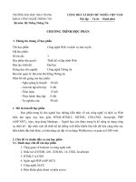
10.20
(a)
BAND4
q0
q1
OUTPUT
q2
zero
q3
mod10
NOT
LoadN
inst1
sload
data[3..0]
down counter
modulus 10
q[3..0]
Data
cnt_en
OUTPUT
ones
OUTPUT
tc
aclr
Enable
q[3..0]
cout
clock
Clock
inst3
inst
NOT
ClearN
inst2
(b)
SUBDESIGN MOD10
( data[3..0], loadn, clrn, clk, en :INPUT;
ones[3..0], tc, zero
:OUTPUT;
)
VARIABLE
count[3..0]
:DFF;
BEGIN
count[].clk = clk;
count[].clrn = clrn;
-- clear the counter asynch
IF loadn == 0 THEN count[].d = data[]; -- load the counter
ELSIF en THEN
IF count[].q == 0 THEN count[].d = 9;
-- reset to 9
--tc = VCC;
ELSE count[].d = count[].q - 1;
-- increment
END IF;
ELSE count[].d = count[].q;
-- hold
END IF;
IF count[] == 0 THEN zero = VCC;
END IF;
tc = en & count[].q == 0;
ones[] = count[].q;
END;
______________________________________________________________________________________________
193
Instructor's Resource Manual – Digital Systems Principles and Applications - 11th edition
___________________________________________________________________________________________________
(c)
ENTITY mod10 IS
PORT
( data :IN INTEGER RANGE 0 TO 9;
loadn, clrn, clk, en
:IN BIT;
ones :OUT INTEGER RANGE 0 TO 9;
tc, zero
:OUT BIT);
END mod10;
ARCHITECTURE digit of MOD10 IS
BEGIN
PROCESS (clk, clrn)
VARIABLE
count :INTEGER RANGE 0 TO 9;
BEGIN
IF clrn = '0' THEN count := 0;
-- asynch clear
ELSIF (clk'EVENT AND clk = '1') THEN -- look for PGT
IF loadn = '0' THEN count := data; -- load data
ELSIF en = '1' THEN
IF count = 0 THEN count:= 9;
-- start over at 9
ELSE count := count - 1;
-- count down
END IF;
END IF;
END IF;
IF count = 0 THEN zero <= '1'; -- mimimum limit of 0
ELSE zero <= '0';
END IF;
IF en = '1' AND count = 0 THEN tc <= '1'; -- mimimum AND enabled
ELSE tc <= '0';
END IF;
ones <= count;
END PROCESS;
END digit;
10.21
(a)
SUBDESIGN
ENCODER
(
key[9..0], clk, enablen :INPUT; -- Individual inputs to encode, clock 10Hz
D[3..0]
:OUTPUT;
-- Encoded data out
pgt_1Hz, loadn :OUTPUT;
-- Data available strobe
)
VARIABLE debounce[2..0] :DFF;
-- make a non recycling counter 0-7
div10[6..0]
:DFF; -- divide by 100
BEGIN
--------MOD 100 to produce 1 Hz out ------------div10[].clk = clk;
IF div10[].Q < 99 THEN div10[].D = div10[].Q + 1; -- count up mod 10
______________________________________________________________________________________________
194
Instructor's Resource Manual – Digital Systems Principles and Applications - 11th edition
___________________________________________________________________________________________________
ELSE div10[].D = 0;
-- synch reset to zero
END IF;
-------Debounce non-recycling counts 0 - 7 and holds. Clears when key released
debounce[].clk = clk;
debounce[].clrn = !loadn;
-- clear counter when key released
IF debounce[].Q < 7 AND loadn == 0 THEN
debounce[].D = debounce[].Q + 1;
-- 0-7 non recycling
ELSE debounce[].D = debounce[].Q;
-- HOLD
END IF;
-------Multiplexer to select clock signal for counter block -----IF enablen == 0 THEN
pgt_1Hz = debounce[2].q;
-- MUX action to output pgt
ELSE
pgt_1Hz = div10[6].Q;
-- CLOCK /100 FOR 1 hZ OUT
END IF;
----Priority key encoder for 0 - 9 with active LOW load strobe
IF
key9 THEN D[] = 9;
ELSIF key8 THEN
D[] = 8;
ELSIF key7 THEN
D[] = 7;
ELSIF key6 THEN
D[] = 6;
ELSIF key5 THEN
D[] = 5;
ELSIF key4 THEN
D[] = 4;
ELSIF key3 THEN
D[] = 3;
ELSIF key2 THEN
D[] = 2;
ELSIF key1 THEN
D[] = 1;
ELSIF key0 THEN
D[] = 0;
END IF;
IF key[] != 0 AND enablen == 0 THEN loadn = GND;
-- load is LOW while key pressed
ELSE loadn = VCC;
END IF;
END;
(b)
ENTITY encoder IS
PORT (
clk, enablen
key
D
pgt_1Hz
loadn
END encoder;
:IN BIT;
--clock 100Hz
:IN BIT_VECTOR (9 DOWNTO 0); -- Individual inputs to encode,
:OUT INTEGER RANGE 0 TO 9; -- Encoded data out
:OUT BIT;
:BUFFER BIT);
-- Data available strobe
ARCHITECTURE vhdl OF encoder IS
BEGIN
PROCESS (clk)
______________________________________________________________________________________________
195
Instructor's Resource Manual – Digital Systems Principles and Applications - 11th edition
___________________________________________________________________________________________________
VARIABLE
debounce :INTEGER RANGE 0 TO 7;
-- delay between key press and
PGT
VARIABLE
div100 :INTEGER RANGE 0 TO 99;
-- mod 100 to produce 1 HZ out
BEGIN
IF ( clk'EVENT AND clk = '1') THEN
----- CONTROL LOAD STROBE
IF key /= "0000000000" AND enablen = '0' THEN -- any keys pressed
loadn <= '0';
-- activate load
ELSE loadn <= '1';
-- deactivate load
END IF;
----- DEFINE DEBOUNCE COUNTER AS 0-7 NON RECYCLING: CLEARS WHEN NO KEYS PRESSED
IF loadn = '1' THEN debounce := 0;
-- clear debounce counter
ELSIF debounce < 7 THEN
debounce := debounce + 1;
ELSE debounce := 7;
-- non recycling. stops at 7
END IF;
---- DEFING MOD 100 TO PRODUCE 1 HZ OUT
IF div100 < 99 THEN
-- MOD 100 counter
div100 := div100 + 1;
ELSE div100 := 0;
END IF;
--- MULITPLEXER CHOOSES BETWEEN DEBOUNCE OUTPUT AND 1 hZ CLOCK
IF enablen = '0' THEN
IF debounce < 4 THEN pgt_1Hz <= '0';
-- OUTPUT pgt FOR COUNTER BLOCK
ELSE pgt_1Hz <= '1';
END IF;
ELSE
IF div100 < 64 THEN pgt_1Hz <= '0'; -- OUTPUT 1 HZ
ELSE pgt_1Hz <= '1';
END IF;
END IF;
END IF;
END PROCESS;
-- Priority key encoder for 0 - 9
d <=
9
WHEN key(9) = '1' ELSE
8
WHEN key(8) = '1' ELSE
7
WHEN key(7) = '1' ELSE
6
WHEN key(6) = '1' ELSE
5
WHEN key(5) = '1' ELSE
4
WHEN key(4) = '1' ELSE
3
WHEN key(3) = '1' ELSE
2
WHEN key(2) = '1' ELSE
1
WHEN key(1) = '1' ELSE
0
WHEN key(0) = '1' ;
END VHDL;
______________________________________________________________________________________________
196
Instructor's Resource Manual – Digital Systems Principles and Applications - 11th edition
___________________________________________________________________________________________________
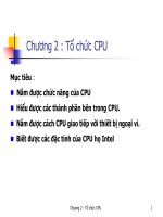
10.22
(a)
NOT
INPUT
VCC
startn
door_closed
inst5
SET
INPUT
VCC
NOT
timer_done
S-R LATCH
AND3
INPUT
VCC
inst2
NOR2
inst1
inst4
NOT
NOR2
inst9
NOT
stopn
INPUT
VCC
OR3
inst12
Q
RESET
OUTPUT
magnetron
inst
inst8
(b)
SUBDESIGN control
(
startn, stopn, clearn, door_closed, timer_done :INPUT;
magnetron
:OUTPUT; -- HIGH = ON
)
VARIABLE
cook :DFF;
-- use DFF for asynchronous preset and clear features
BEGIN
cook.clk = GND;
-- just using asynch inputs. Not using clock or D
cook.d = GND;
cook.prn = !(!startn & door_closed & !timer_done);
-- start only if door closed w/time on clock
cook.clrn = !(!stopn # !clearn # !door_closed # timer_done);
-- turn off mag under these circumstances
magnetron = cook.q; -- connect DFF output to block output port
END;
(c)
ENTITY control IS
PORT
(startn, stopn, clearn, door_closed, timer_done :IN BIT; -- n suffix designates active
LOW.
magnetron
:BUFFER BIT); -- HIGH = ON
END control;
ARCHITECTURE on_off OF control IS
BEGIN
PROCESS (startn, stopn, clearn, door_closed, timer_done)
BEGIN
IF (startn = '0' AND door_closed = '1' AND timer_done = '0') THEN
magnetron <= '1';
-- start (set) only if door closed w/time
on clock
______________________________________________________________________________________________
197
Instructor's Resource Manual – Digital Systems Principles and Applications - 11th edition
___________________________________________________________________________________________________
ELSIF (stopn = '0' OR clearn = '0' OR door_closed = '0' OR timer_done =
'1') THEN
magnetron <= '0';
-- turn off (clear) nukes under these circumstances
ELSE magnetron <= magnetron;
-- stay the same state as it was
(latch)
END IF;
END PROCESS;
END on_off;
10.23
(a)
(b)
SUBDESIGN decode
(
sec_ones[3..0]
:INPUT;
-- lower digit = seconds
sec_tens[3..0]
:INPUT;
-- middle digit = 10s of seconds
min[3..0]
:INPUT;
-- upper digit = minutes
sec_ones_segs[0..6]
:OUTPUT;
-- active LOW LED drive for 7
segment
sec_tens_segs[0..6]
:OUTPUT;
-- note order [0..6] <-> [a..g]
min_segs[0..6]
:OUTPUT;
-)
BEGIN
% NOTE LOW digit always displays zero %
TABLE
sec_ones[]
=>
sec_ones_segs[];
0
=>
1;
-- Display a zero
1
=>
H"4f";
2
=>
H"12";
3
=>
H"06";
4
=>
H"4C";
5
=>
H"24";
6
=>
H"20";
7
=>
H"0F";
8
=>
H"00";
______________________________________________________________________________________________
198
Instructor's Resource Manual – Digital Systems Principles and Applications - 11th edition
___________________________________________________________________________________________________
9
END TABLE;
=>
H"04";
IF min[] == 0 & sec_tens[] == 0 THEN
-- detect leading zeros
sec_tens_segs[] = H"7F";
--blank the display
ELSE
TABLE
-- blanking for middle digit
sec_tens[]
=>
sec_tens_segs[] ;
0
=>
1;
-- Display a zero
1
=>
H"4f";
2
=>
H"12";
3
=>
H"06";
4
=>
H"4C";
5
=>
H"24";
6
=>
H"20";
7
=>
H"0F";
8
=>
H"00";
9
=>
H"04";
END TABLE;
END IF;
TABLE
min[]
=>
min_segs[];
-- This is most significant digit
0
=>
H"7F";
-- always blank leading zero
1
=>
H"4f";
2
=>
H"12";
3
=>
H"06";
4
=>
H"4C";
5
=>
H"24";
6
=>
H"20";
7
=>
H"0F";
8
=>
H"00";
9
=>
H"04";
END TABLE;
END;
(c)
ENTITY decode IS
PORT
( lo, mid, hi
:IN INTEGER RANGE 0 TO 9;
-- lo = seconds, mid= 10s of seconds, hi = minutes
ha, hb, hc, hd, he, hf, hg
:OUT BIT;
-- active LOW LED drive: minutes
ma, mb, mc, md, me, mf, mg :OUT BIT;
-- tens of seconds
la, lb, lc, ld, le, lf, lg
:OUT BIT);
-- ones of seconds
END decode;
______________________________________________________________________________________________
199
Instructor's Resource Manual – Digital Systems Principles and Applications - 11th edition
___________________________________________________________________________________________________
ARCHITECTURE display OF decode IS
SIGNAL losegs :BIT_VECTOR (6 DOWNTO 0);
SIGNAL midsegs, hisegs :BIT_VECTOR (6 DOWNTO 0);
BEGIN
-- This section drives the least significant digit
-- NOTE LOW digit always displays zero
WITH lo SELECT
losegs <=
"0000001" WHEN 0,
"1001111" WHEN 1,
"0010010" WHEN 2,
"0000110" WHEN 3,
"1001100" WHEN 4,
"0100100" WHEN 5,
"0100000" WHEN 6,
"0001111" WHEN 7,
"0000000" WHEN 8,
"0000100" WHEN 9,
"1111111" WHEN OTHERS;
-- This section drives the middle digit and requires zero blanking logic
PROCESS(mid, hi)
BEGIN
IF hi = 0 AND mid = 0 THEN
midsegs <= "1111111";
ELSE
CASE mid IS
WHEN 0
Display a zero
WHEN 1
Display 1
WHEN 2
WHEN 3
WHEN 4
WHEN 5
WHEN 6
WHEN 7
WHEN 8
WHEN 9
Display 9
END CASE;
END IF;
END PROCESS;
-- This section drives the most significant digit
WITH hi SELECT
hisegs <=
"1111111" WHEN 0,
-- detect leading zeros
--blank the display
=>
midsegs <="0000001"; --
=>
midsegs <="1001111"; --
=>
=>
=>
=>
=>
=>
=>
=>
midsegs <="0010010";
midsegs <="0000110";
midsegs <="1001100";
midsegs <="0100100";
midsegs <="0100000";
midsegs <="0001111";
midsegs <="0000000";
midsegs <="0000100"; --
-- always blank when zero
______________________________________________________________________________________________
200
Instructor's Resource Manual – Digital Systems Principles and Applications - 11th edition
___________________________________________________________________________________________________
"1001111" WHEN 1,
"0010010" WHEN 2,
"0000110" WHEN 3,
"1001100" WHEN 4,
"0100100" WHEN 5,
"0100000" WHEN 6,
"0001111" WHEN 7,
"0000000" WHEN 8,
"0000100" WHEN 9,
"1111111" WHEN OTHERS;
(la, lb, lc, ld, le, lf, lg) <= losegs;
-- connect internal signals to outputs
(ma, mb, mc, md, me, mf, mg) <= midsegs;
(ha, hb, hc, hd, he, hf, hg) <= hisegs;
END display;
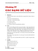
10.24
Frequency Counter
Display
Latch
Decoder
Counter
7-seg
Timing & Control
Clock
Prescaler
MOD-10
MOD 10
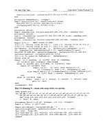
10.25
MUX
Timing
MOD-6
Decoder
Pulse
Shaper
% MOD 6 used in FREQ COUNTER project
counts 0-5 decodes three states: clear = 0, enable = 2, store = 4 %
SUBDESIGN PROB10_25
(
clock
q[2..0]
clear, enable, store:OUTPUT;
)
VARIABLE
count[2..0]
:DFF;
:INPUT;
:OUTPUT;
-- synch clock
-- 3-bit counter
-- timing signals
-- declare a register of D flip flops.
BEGIN
count[].clk = clock;
IF count[].q < 5 THEN
count[].d = count[].q + 1;
ELSE count[].d = 0;
END IF;
q[] = count[].q;
-- connect all clocks to synchronous source
-- increment current value by one
-- force unused states to 0
-- connect register to outputs
CASE count[] IS
______________________________________________________________________________________________
201
Instructor's Resource Manual – Digital Systems Principles and Applications - 11th edition
___________________________________________________________________________________________________
WHEN 0
WHEN 2
WHEN 4
WHEN OTHERS
END CASE;
=>
=>
=>
=>
clear = VCC; enable = GND; store = GND;
clear = GND; enable = VCC; store = GND;
clear = GND; enable = GND; store = VCC;
clear = GND; enable = GND; store = GND;
END;
---
MOD 6 for FREQ COUNTER PROBLEM
counts 0-5 decodes three states: clear = 0, enable = 2, store = 4
ENTITY prob10_25 IS
PORT( clock
q
clear, enable, store
END prob10_25;
ARCHITECTURE a OF prob10_25 IS
BEGIN
PROCESS ( clock)
VARIABLE count
:IN BIT ;
:OUT INTEGER RANGE 0 TO 5;
:OUT BIT
);
-- respond to clock
:INTEGER RANGE 0 TO 5;
BEGIN
IF (clock = '1' AND clock'event) THEN
IF count < 5 THEN
count := count + 1;
ELSE
count := 0;
END IF;
END IF;
q <= count;
CASE count IS
WHEN 0
WHEN 2
WHEN 4
WHEN OTHERS
END CASE;
END PROCESS;
-- maximum (terminal) count
-- update outputs
=>
=>
=>
=>
clear <= '1'; enable <= '0'; store <= '0';
clear <= '0'; enable <= '1'; store <= '0';
clear <= '0'; enable <= '0'; store <= '1';
clear <= '0'; enable <= '0'; store <= '0';
END a;
10.26
% MUX for Freq Counter %
SUBDESIGN prob10_26
(
1Hz, 10Hz, 100Hz, 1KHz, 10KHz, 100KHz
:INPUT;
s[2..0]
:INPUT; -- select inputs
freqout
:OUTPUT;
)
BEGIN
CASE s[] IS
WHEN 0 =>
freqout = 1Hz;
WHEN 1 =>
freqout = 10Hz;
______________________________________________________________________________________________
202
Instructor's Resource Manual – Digital Systems Principles and Applications - 11th edition
___________________________________________________________________________________________________
WHEN 2 =>
WHEN 3 =>
WHEN 4 =>
WHEN 5 =>
freqout = 100Hz;
freqout = 1KHz;
freqout = 10KHz;
freqout = 100KHz;
END CASE;
END;
--
MUX for Freq Counter
ENTITY prob10_26 IS
PORT(
Hz1, Hz10, Hz100, KHz1, KHz10, KHz100
s
freqout
END prob10_26;
ARCHITECTURE truth OF prob10_26 IS
BEGIN
WITH s SELECT
freqout <=
Hz1
:IN BIT;
:IN INTEGER RANGE 0 TO 5;
:OUT BIT
);
WHEN 0,
Hz10 WHEN 1,
Hz100 WHEN 2,
KHz1 WHEN 3,
KHz10 WHEN 4,
KHz100 WHEN 5;
--switch 1 to output y
--switch 10 to output y
--switch 100 to output y
--switch 1k to output y
--switch 10k to output y
--switch 100k to output y
END truth;
10.27
10.28
----
prescaler made from 5 MOD10 modules
freq cntr project in Chapter 10
used in problem 10-28
include "fig10_26.inc";
SUBDESIGN prescaler
-- mod-10 counter module
(
clk
freqs[5..0]
: INPUT;
: OUTPUT;
______________________________________________________________________________________________
203
Instructor's Resource Manual – Digital Systems Principles and Applications - 11th edition
___________________________________________________________________________________________________
)
VARIABLE
KHZ10
KHZ1
HZ100
HZ10
HZ1
: fig10_26;
: fig10_26;
: fig10_26;
: fig10_26;
: fig10_26;
-- mod-10
BEGIN
KHZ10.clock = clk;
-- synchronous clocking
KHZ10.enable = VCC;
KHZ1.clock = clk;
KHZ1.enable = KHZ10.tc;
Hz100.clock = clk;
HZ100.enable = KHZ1.tc;
Hz10.clock = clk;
HZ10.enable = HZ100.tc;
Hz1.clock = clk;
HZ1.enable = HZ10.tc;
freqs[] = (clk, KHZ10.tc, KHZ1.tc, HZ100.tc, HZ10.tc, HZ1.tc);
END;
--
Timing and Control section of freq cntr project in Chapter 10
include "prescaler.inc";
include "prob10_26.inc";
include "prob10_25.inc";
SUBDESIGN T_and_C (
clk, freq_range[2..0]
clear, enable, store
)
: INPUT;
: OUTPUT;
VARIABLE
presc
: prescaler;
-- frequency prescaler
fmux
: prob10_26;
-- multiplexer selects freq
control
: prob10_25;
-- control signal generator
BEGIN
presc.clk = clk;
(fmux.KHZ100, fmux.KHZ10, fmux.KHZ1, fmux.HZ100, fmux.HZ10, fmux.HZ1) = presc.freqs[];
control.clock = fmux.freqout;
clear = control.clear;
enable = control.enable;
store = control.store;
fmux.s[] = freq_range[];
END;
______________________________________________________________________________________________
204