A overew of design considerations for smal recircuating fish culture systems
Bạn đang xem bản rút gọn của tài liệu. Xem và tải ngay bản đầy đủ của tài liệu tại đây (2.74 MB, 15 trang )
An Overview of Design Considerations for
Small Recirculating Fish Culture Systems
T.S. Harmon
Walt Disney World Co.
P.O. Box 10,000
Lake Buena Vista, FL 32830 USA
ABSTRACT
Aquatic system engineering is an important factor when designing a
new fish holding system or renovating an existing system. Indoor
recirculating aquatic systems may be used for various operations, some
of which may include: the quarantine of new animals, isolation for ill
fish, aquaculture, research, or as educational displays. Professional
engineers generally design large or high-density systems using a mass
balance approach. However, smaller systems are typically designed or
renovated by their immediate owners, which may include
aquaculturalists, aquarists, biologists, zoologists, or professors. In many
instances trial and error is used to size the equipment, which can get very
expensive and take up valuable time. Undersized or oversized equipment
wastes electricity and possibly reduces the life of the equipment. These
limitations can be avoided by using the practical guidelines given here
and taking into consideration a few simple design factors. Proper design
of these systems can be accomplished by much quicker methods than a
full-scale mass-balance approach and will typically work for low-density
systems.
International Journal of Recirculating Aquaculture, volume 2
5
INTRODUCTION
Recirculating systems offer two distinct ad vantag es ; the control over
certain water q uality p arame ters , and water conservation. Most water
reconditioning systems recycle 90-95% of the water (Piper et al. 1982).
A dai ly water loss may be necessary due to backwashing of filters as
well as for the removal of nitrates (Lawson
1995). U ni versi ties and high
schools often use recirculating aquatic sys tems for studyi ng aq uatic
animals and their behaviors, while other universities may use them for
aquacultural research. Public aquariums
and zo olo gical institutions that
have aquatic exhibits may also have holding facilities to receive and
quarantine new animals as well
as
to care for ill animals. All
recirculating aquatic systems s hould be designed according to their
in tended use. Moreover, a facility or system is often turned into another
with a different use later on. Reusing existin g equipment can be very
co s t-effective, but we mus t consider the required com ponents
and the
limitations of the original design before placing a load of fish into an
existing system and expecting good results .
Facility or system design depends directly upon the desired use of a
system . Typical uses may i nclud e: display exhibits, q uaran tine , hos pital
tanks, hold ing, breeding , growout, spaw ning or any combina tion of
these. E ven after the original applicatio n is decided the actual
components needed may d epend upon another set of factors. These
factors may includ e: water availability and cost, feeding rates , fish
density, electrical availability, maintenance, and climate. Small or large
recirculating systems alike require five basic components to run
prop erly; a tank of adeq uate shape and size, good aeration, pumps,
mechanical filters, and bi ological filters. De sign of each of these
co mp onen ts is crucial, as th e y are essential for the sys tem 's overall
performance.
HOLDING CONTAINERS
There are many different types, shapes, and siz es of holding tanks
available today, with the most popular being circ ular or rectang ular.
Much of the selection with tank shape is bas ed on personal preferences ,
although some have distinct ad vantages over others. A major contrast
outlined by Piedrahita ( 1991) is that the water q uality in circular tanks
International Journal of Recirculating Aquaculture, volume 2
tends to be uniform, while rectangular raceways are characterized by a
distinct degradation of water quality between the inlet and outlet.
Rectangular tanks can be placed side by side. with little wasted space
between
them. Ellis (1994) found rectangular tanks to be superior over
circular designs in survivability, feed c onversion , yield, and growth of
Florida red tilapia fry. If flow rates are not adjusted correctly in
raceways, they can act as
a
solids settling device: Boersen and Westers
(1986) and Kindschi et al: (1991) found that adding baffles to raceways
prevented solids from settling out within the raceway, making for easy
removal at the end of the raceway. Dividers can also be easily
constructed and placed into narrow rectangular tanks compared to
circular tanks.
Circular tanks offer the distinct advantage of being "self-cleaning".
Incoming water can be angled to
create
a circular motion in the tank with
the soli ds being swept towards the middle where they are removed by a
center drain. Lawson (1995) reminds us that flow veloc ity must not be so
great that the fish expend all of their energy swimming. Mo reover, tanks
with high water
velocities may keep particulate matter suspended and
create conditions in which gill irritation develops (Wedemeyer 1996).
The ideal flow velocity for fish will vary between species and even
within a species depending on the condition and size of fish.
AERATION
Dissolved oxygen (DO) is a limiting factor in fish culture (Piper et al.
1982). Inadequate DO levels may lead to reduced growth, an increase in
disease, and can cause mass mortali ty (Colt and Tchobanoglous 1981).
As the stc;>cking density and food intake increases in a system, so must
the amount of available oxy gen . Species, life stage,size, and
fish, as well as overall environmental
co nditi ons are all variables which can affect the amount. of oxygen
physiological condition of the
consumed by the system. In most c ases , long-term DO levels above
6.0
mg/I will prevent any problems associated with .oxygen deficiency in any
species of fish. Warm water fish generally tend to tolerate lower DO
levels for longer periods, whereas cool or cold water fish tend to require
higher levels over the long term.
International Journal of Recirculating Aquaculture, volume 2
7
Subsurface aeration techniques are the most common among lightly
loaded fish holding systems. In facilities that are planning for high
(1981)
( 1988) describe different types of pure oxygen
densities of fish, pure oxygen injection may be preferred. Speece
and Colt and Watten
systems and their uses.
For low densities of fish, using professional judgment from previous
personal experience or from the experience of colleagues can be a great
help and save time with calculations in determining the correct size of
the aeration device. If previous experience is limited, it is recommended
that the actual amount of oxygen consumed by the fish be taken into
consideration (Table
1). Even among the same species, oxygen uptake
can be inconsistent because of the many variables that are involved with
the rate of oxygen consumption. Rusch
(2000) described a quick
approach to oxygen consumption design suitable for small or lightly
loaded systems, where fish use 220 g O.j kg of feed and bacteria in the
system consume about 75% of the fish consumption rate
(165 g 0.jkg
feed). A mass-balance approach described by Losordo (1991) is typically
used to design high-density aquaculture systems.
Considerations such as the DO level entering the tank and turnover
rates are also important in designing an aeration system. Assuming an
incoming DO level of 0 mg/I can provide a safety margin by not relying
on the system's passive aeration to maintain proper DO levels.
Air blowers or air compressors are usually the choice for subsurface
aeration devices. Air blowers are designed to provide large volumes of
air at low pressures (< 4 lb/in2 (psi),
1 Bar= 14.5 psi) with the opposite
holding true for air compressors. Correct sizing is critical for both
blowers and compressors. Oversizing can generate excess amounts of air
and may need to be "blown off'. One that is too small may not fully
supply all the airstones, or operate only at shallow depths. The total
amount of pressure and volume of air is required knowledge for sizing an
aeration device, and is dependent upon three variables:
(I)
The depth of water at which the airstone(s) will be operated:
lpsi
(2)
=
0.7 m of water at 15.6°C.
Different size diffusers and pore size will determine the amount
of air needed to operate them: The volume needed is usually
International Journal of Recirculating Aquaculture volume 2
,
given in liters per minute or cubic feet per minute (CFM),
(1 CFM = 28.3 Umin). This can be obtained from the
manufacturer of the diffuser; most airstones used for small
systems are well under 28 Umin. A total volume from all
diffusers used is required for a total volume of air.
(3)
pipe: Creswell (1993) compiled
information on frictional losses (psi loss/30.5 m pipe) for
air as a function of pipe size and flow rate.
Friction losses in the
Once the volume of air required, amount of pressure (psi) required,
and type of aeration device preferred is known, a simple graph provided
by the supplier will give the proper size compressor or blower that is
needed for the j ob.
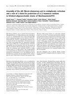
Table 1. Oxygen consumption values for various freshwaterfish species.
Size
Species
(g)
Temp 02 consumption
(oC) (mg/kg/day)
Ori&inal Source
806
100
12
1,921
10
4,080
Beamish 1964<2>
100
20
11,520
100
25
16,800
Beamish 1964C2>
Beamish 1964C2>
Oncorhynchus
nerka
28.6
15
6,600
28.6
15
5,600
Ictalurus
punctatus
100
100
100
26
14 ,600
30
30
13,440
Andrews & Matsuda 1975<1
Andrews & Matsuda I 975C2
19,440
Andrews & Matsuda 1975<2
73
11
Nakanishi & Itazawa 19740
100
15
2 ,9 1 7
7,200
Cyprinus
carpio
Oncorhynchus
my kiss
Sources taken from:
( 1)
(2)
(3)
Nakanishi & Itzawa 1974<1>
Brett & Zala 1975<3>
Brett & Zala 1975<3>
Liao 1971
<2>
Kepenyes and Varadi ( 1 983)
Creswell (1993)
Colt and Tchobanoglous (1981)
International Journal of Recirculating Aquaculture, volume 2
9
PUMPS
Recirculation systems generally utilize pumps for moving
water from
the tank through filters or from a sump through
a filtering s ystem.
Although multiple factors play into the required flow rates, a tank
exchange of at least once an hour is usually sufficient to maintain the
water quality needed for proper fish health. If a heavy feeding regime or
excellent clarity is necessary, a quicker turnover rate should be
considered. Wheaton et al. (1997) uses oxygen consumption as a factor
in the detennination of flow rate. Losordo and Westers (1997) review the
mass-balance approach, where the desired flow rate is computed by
taking variables such as dissolved oxygen and
ammonia
concentrations
into consideration.
Four items of information
(1)
Desired flow rate
(2)
Friction loss
are
needed to correctly size a pump:
from the piping and fittings
(suction & discharge side)
(3)
Vertical distance over which the water is to be pumped
(4)
Pressure required by filters
on friction
selected valves and fittings as "equivalent length of pipe".
Using this information, the total length of all fittings is added to the
length of straight pipe needed to give a total length of pipe, which is then
used in the Hazen- Williams formula. Major pipe sizes and their
corresponding friction losses are shown in Table 2. Lawson ( 1997)
recommends using a C-value (Hazen-Williams coefficient for various
pipe materials) of 100 for permanent installations of PVC piping due to
future biofouling; new PVC pipe has a C-value of 150. This calculation
along with vertical lift and pressures required by any filters will give the
total dynamic head. This information along with the desired flow rate
will determine which size pump is best suited for the application.
Creswell (1993) and Lawson (1997) gathered information
losses for
l 0 International Journal of Recirculating Aquaculture, volume 2
Table2
Losses are given in headfeet per 30.5 m (100') ofpipe using ·the Hazen-Williamsformula.
A C-value of 130 is used as the coefficient w:ing Sclul. 4() PVC pipe. Velocity (v) is given in
ft/sec (l ft/sec = 18.29 mlmin). Divide the loss (headfeet) by 3.28 to obtain meters of
head. LPM is liters per minute, a� GPM is gallons per minute.
Pipe Size. mm
LPMGPM
(in)
38(l..5)
50(2)
25(1)
19 (0..75)
Velocity. Loss Velocity Loss Velocity Loss Velocity
Loss
19
(5)
10.17
3.63
39
(10)
36.73
7.26
9.0S
4.09
1.26
1.82
0.31
1.02
78
(20)
132.58
14.52
32.67
8.17
4.53
3.63
1.12
2.04
116
(30)
69.21
12.26
9.61
5.45
2.37
3.06
155
(40)
117.9
16.34
16.37
7.26
4.03
4.09
194
(50)
178.24
20.43
24.75
9.08
6.10.
.5.11
233
('8)
34.68
10.89
8.54
6.13
271
(70)
10.99
7.15
310
(80)
13.43
8.17
349
(90)
15.89
9.19
388
(100)
18.37
10.21
(1988) notes that for general service applications
velocity is not to exceed 3.0 m/sec (IO ft/sec).
Note: Crane
a
reasonable
International Journal of Recirculating Aquaculture; volwne.2
11
FILTRATION
Recirculation systems rely u pon filtration to remove waste products
and to carry out the nitrification processes. Basic components of a
recirculation system often include: mechanical filtration, biological
filtration, sterilization, and heating/cooling. Various tertiary components
such as fractionators and carbon filters may also be added to a system.
Mechanical filters are typically the first filters in a filtration sequence.
Manufacturers will rate mechanical filters according to a flow rate and
are sized accordingly. A good review of mechanical filters is found in
Wheaton (1977), Chen et al. ( 1997), and Lawson ( 1997). The biological
filtration of interest for fisheries professionals is the nitrification process
in which several genera of autotrophic bacteria convert
amm onium
(NH/) to nitrite (NO;) then to nitrate (NQ3-) (Wheaton 1977). Biofilters
provide a large surface area for nitrifying bacteria to colonize, which the
water has to pass over or through. A biological filtering device should be
located following the mechanical filter. Reliable reviews of biological
filtration devices used in fish systems include: Wheaton (1977); Rogers
(1985); Malone et al . (1993); Westerman et al. (1993); and Wheaton et
al. (1997).
Biological filtration design is not an exact science in fish systems due
to limited scientific literature on ammonia production by fish and
inconsistencies in the data that do exist (Wheaton 1997). Malone et al.
(1993) also expresses that 30-60% of nitrification can take place outside
of the biofilter: Biological filters are sized according to the amount of
surface area that is needed for nitrifying bacteria. Meade (1985)
reviewed information on fish ammonia production and found ranges of
20-78 . 5 g/kg - diet/day. Three out of the five sources cited by Meade
found production rates between 31-37.4 g/k.g-diet/day. Piper (1982)
found that much of the literature on trout and salmon total ammonia
production rates, which were fed a dry-pelleted food, produced 32 g/kg
food. For smaller, lightly loaded systems, submerged or trickling
biofilters are commonly used and are relatively inexpensive. Wheaton
( 1977) reviewed literature on nitrification rates for a submerged gravel
biofilter to be 1.0 g/NH3-N/m2-day at 20°C. Miller and Libey (1985)
found a trickling filter to have removal rates from 0.14-0.25 g N/m2-day.
Bead filters were found to have removal rates of 0.27 g TAN/m2/day
12 International Journal of Recirculating Aquaculture, volume 2
(Lawson 1995). Using these
determine the surface
amm onia
findings, the following formula is used to
area needed.
produced (g)
------
=
m2 surface area
ammonia removal (g/m2/day)
Poor performance of biofilters is most often caused by uneven flow
across all of the media (Hochheimer and Wheaton 1991). The nitrifying
bacteria must have
an ample supply of nutrients and an adequate supply
of oxygen to survive. Hochheimer and Wheaton
(1991) review various
chemical factors that may inhibit nitrifying bacteria growth.
Losordo (1991) and Laws on (1995) describe a mass-balance approach to
biological filter design that is commonly used for the design of high
physical and
density systems.
CALCULATIONS
The following example is for a recirculating system used as
a
area for freshwater fishes. The following information is used in
holding
the
design process:
A.
S chool aquaculture system for warm. water fish.
Total weight of fish not to exceed 50 kg.
B.
Total feed is not
to
exceed 2 kg/day.
C.
2835 L(750 gal) system; 2- 945 L circular tanks and
D.
Components consist of a sand filter, trickling biofilter,
1- 945 L rectangular trough.
UV sterilizer, and supplemental aeration.
1.
Turnover rate lx/hr.
(2835 L /60 min= 47.25 Umin <13 gpml
FLOW RATE:
One inch Schd. 40 PVC pipe will be used, which will have a
(3 ft/sec) and a head loss
(15 feet) head/30.5 m pipe (Table 2).
velocity of about 91.5 m/min
4.5 meters
International Journal of Recirculating Aquaculture,
of around
volume 2
13
2.
PLUMBING FITTINGS: From Creswell (1993), the
following losses are gi ven in equ i vale nt length of pipe:
DISCHARGE (Outflow)
SUCTION (Inflow)
Qty. Part
90° elbows
8
Qty.
Equiv. Pipe
6.4 m pipe
4
45°elbows
1.7
2
Tees
32
2
Gate
Equiv. Pipe
90° elbows
1.5 m pipe
Straight pipe
0.9
.
TOTAL SUCTION
(branch flow)
6
Part
Valves
2.4mpipe
2.1
(open )
Straight pipe
30
.
TOTAL DISCHARGE 16.4m pipe
3.
FILTRATION COMPONENTS: Vertical distance from su mp
water to the hig hes t point; where the water is discharged i nto the
tric kling filter = 2 m
Sand
UV=
4.
filter= 3 psi= 2.1 meters head
minimal (from manufacturer)
TDH (total dynamic head): TDH =friction head + pressure
head+ static h ea d + velocity head (minimal)
18.8 m pipe (suction+ discharge)
(from #1,Table 2.0)
m)(4 .5 m/30.5 m) = 2.8 m
Head loss 4.5 m/30.5 m pipe
(18.8
velocity head = velocity2 I 2g = V2/2(32.2)
g
=
=
(minimal)
gravitational constant
TDH
=
2.8
+
2.1
+
2
=
6.9 meters head
Therefore, a pump that would supply 47 Umin
(13 gpm) at 7
meters of head is neede d It is rec ommended that a pump that is
.
slightly larger be used to take into consideration any plumbing
modifications that may be considered later.
14
International Journal of Recirculating Aquaculture, volume 2
5.
AERATION REQUIREMENTS: From Table 1 we find
14,600 mg/kg/day 0 consumption for catfi sh at 26°C.
2
(50 kg fish)(14,600 mg/kg/day)
=
730,000 mg /day 02
consumption
According to a sup plier, a 1 5 cm
8 g O/h r (192,000mg 0.jday).
(6") airstone has an output of
730,000 mg/day 02 consumption
192,000 mg O.j day output each
=
(4) 15 cm airstones
Note: Because we are using a trickling filter, which will also
oxygenate the wa ter, oxygen consumed by bacteria is not
included. Also, water entering the tank is assumed to have a DO
level
6.
of 0 mg/I.
AERATION DEVICE: 15 cm airstones
are s ugg ested to run at
14 Umin (supplied from manufacturer) each.
14 Umin (4)
=
56 Umin
Friction loss due to flow and pi pe size is minimal for this volume
of air (Creswell 1993 ). With a depth of 0.7 m, about 1 psi of
press ure is required. This minimal air volume will require a small
air pump capable of 60 Umin @ 1.5-2 psi.
figures there is a buffer.
7.
and using these
BIOWGICAL: Feeding at a rate of 2 kg/day and using a
production rate of 35g N/kg feed = 70 g N produced/day
Using
a removal rate of 0.14 g/m2/day for a trickling filter
70gN
-----
=
500 m2 surface area
0.14 g/m2/day
2.54 cm bioballs
=
532 m2 surface area/m3 (given by supplier)
Therefore, one cubic meter of bioballs is needed for the
trickling filter.
International Jm.tmal of Recirculating Aquaculture, volume 2
15
CONCWSIONS
are only a few of many needed for the
of an aquatic holding system. However, this paper will give the
non-engineer a starting point in the design phase and eliminate some of
the guessing that is often involved in system design. Proper design of
any system is the basis for its performance. Without proper design, water
quality will likely limit the systems cap ability to properly house healthy
fish over a period of time. Moreover, by being involved in the design
phase of a system, the owner will better understand the limits of the
system.
The considerations mentioned
design
16 International Journal of Recirculating Aquaculture, volume 2
REFERENCES
Boersen, G., Westers, H. Waste Solids Control in Hatchery Raceways.
The Progressive Fish Culturalist
Chen, S., Stechey, D.,
M alone
,
1986. 48,
151-154.
R.F. Suspended Solids Control in
Recirculating Aquaculture Systems. In Aqu ac ulture Water Reuse
Systems : Engineering Design and Management; Timmons, M.B. and
Losordo,
T.M., Eds. 1997. Elsevier: New York, NY, USA.
Colt, J.E., Tchobanoglous, G. Design of Aeration Systems for
Aquaculture. In Proceedings of the Bio-engineering Symposium for
Fish" Culture; Allen, L.J. and Kinney, E.C., Eds. 1981. American
Fisheries Society, Bethesda,
MD, USA.
Watten, B. Applications of Pure Oxygen in Fish Culture.
Aquacultural Engineering 1988. 7, 397-44 1.
Colt, J.,
Crane Co.
1988.
Flow of Fluids Through Valves. Fittings. and Pipe.
Crane Co., Joliet, n.., USA.
1993. Aquaculture Desk Reference. Chapman and Hall:
New York, NY, USA.
Creswell, R.L.
Ellis, S.C., Watanabe, W. Comparison of Raceway and Cylindroconical
Tanks for Brackish-Water Production of Juvenile Florida Red Tilapia
Under High Stocking Densities. Aquacultural Engineering
1994.
13,
59-69.
Hochheimer, I.N., Wh eaton, F.W. Und erstanding Biofilters, Practical
Microbiology for Ammonia Removal. In Engineering Aspects of
Intensive Aquaculture:
Procee dings from the Aquaculture
Symposium. NRAES-49; 1991. Northeast Reg ional Agricultural
Engineering Service, Ithac a, NY, USA.
Kepenyes, J., Varadi, L. Aeration and Oxygenation. In Inland
ADCPIREP/84/21; Pillay, T. V. R., Clay,
C.H., Kovart, J., Eds. 1984. Food and Agriculture Organization of
Aquaculture En�ineering.
th e United Nations, Rome, Italy.
International Journal of Recirculating Aquaculture, volume 2
17
Kindschi, G.A., Thompson,
R.G., Mendoza, A.P. Use of Raceway
Baffles in Rainbow Trout Culture. The Progressive Fish
1991. 53, 97-101.
Lawson, T.B. 1995. Fundamentals of Aguacultural
Chapman and Hall: New York,
NY, USA.
Culturalist
Ensineering.
Losordo, T.B. An Introduction to Recirculating Production System
Design . In Enaineerin1 Aspects of Intensive Aqyacµlture:
1991.
Engineering Service. Ithaca, NY,
Proceedings from the Aquaculture Symposium. NRAES-49;
Northeast Regional Agricultural
USA
.
·
.
Losordo, T.M.,Westers, H.
System Carrying Capacity and Flow
Estimation. In Aquaculture Water Reuse Systems : Engineering
Design and Management: Timmons, M.B., and Losordo, T.M., Eds.
1997. Eisevier: New York, NY, USA.
Malone, R.F., Chitt_a, B.S., I;>rennan,
D.G. Optimizing Nitri�c.ation �
Bead Filters for Warmwater Recircitlating Aquaculture Systems. In:
Techniques for Modem Aquaculture (Proc.); Wang, J.K;, Ed.
American Society of Agricultural
l993.
Engine�rs. St. Joseph, MI, USA.
Meade, J.W. Allowable Ammonia for Fish Culture. The Progressive Fish
Culturt#ist 1985. 47(2), 135-145.
Miller, G.E., Libey, G.S. Evaluation of Three Biological.Filters Suitable
for Aquacultural Applications. Journal of World Mariculture
1985. 16,158-168.
Society
Piedrahita, R.H. Engineering _Aspects of Wannwa�er Hatchery Design.
In Aguaculture Systems En&ineering
Engineers, St. Joseph, MI, USA.
·
Piper, R.G., McElwain, I.B., Orme, L.E., McCraren, J.P., Fowler,
Leon ard, J.J_l.1982.
.
the Interior,
Fish Hatchery Management. U.S. Departm�nt of
Fish and Wtldlife Service, Washington, DC; '(JSA�
Rogers, G.L., Klemetson, S.L. Ammonia Remov al in Selected
Aquaculture Water Reuse
1985.
L.G.,
Biofilters. Aquacultural Engineering
4,135-154.
18 International Journal of �circulating Aquaculture, volume 2
Quality Principles. In Recirculatim� System
Fundamentals, Special Session Proceedings from the World
Aquaculture Society Annual Conference, 2000. Aquacultural
Rusch. K. B asic Water
Engineering Society.
Spee ce , R.E. Management for Dissolved Oxygen and
Nitrogen in Fish
Hatchery Waters. In Proceedings of the Bio-Engineering Symposium
for Fjsh Culture. Allen, L.J. and Ki nney, E.C.,
Eds.
1981. American
Fisheries Society, Bethesda, MD, USA.
Wedemeyer, G.A. 1996. Physiology of Fish in Intensive Culture
Systems. Chapman and Hall: New York, NY, USA.
Westerman, P.W., Losordo, T.M., Wildhaber, M.L.
Evaluation of
Various Biofilters in an Intens i ve Recirculating Fish Production
Technigues for Modern Aquaculture (Proc.). Wang, J.K.,
Ed. 1993. American Society of Agricultural Engineers, St. Joseph,
Facility. In
MI, USA.
Wheaton, F.W.1977.
Aquacultural Engineering. John Wiley and Sons:
New York, NY, USA.
Malone, R.F., Krones,
Easter, C.C. Nitrification Filter Design Methods in
Aquaculture Water Reuse Systems: Engineering Design and
Management. In Aquaculture Water Reuse Systems:Engineering
Design and Management. Timmons, M.B., and Losordo, T.M. Eds.
1997. Elsevier: New York, NY, USA.
Wheaton, F.W., Hochheimer, J., Kaiser, G.E.,
M.J., Libey, G.S.,
International Journal of Recirculating Aquaculture, volwne 2
19