Analysis of a recirculating aquaculture system
Bạn đang xem bản rút gọn của tài liệu. Xem và tải ngay bản đầy đủ của tài liệu tại đây (16.85 MB, 54 trang )
Figure 0.1: Clarias Gariepinus, Illustrations of the Zoology of South Africa, 1838
Analysis of a Recirculating Aquaculture
System
An analysis at Lantfisk
Master’s thesis in Innovative and Sustainable Chemical Engineering
Amanda Andersson and Måns Gerdtsson
Department of Architecture and Civil Engineering
C HALMERS U NIVERSITY OF T ECHNOLOGY
Gothenburg, Sweden 2018
Master’s thesis ACEX30-18-91
Analysis of a Recirculating Acuaculture System
An analysis at Lantfisk
Amanda Andersson
Måns Gerdtsson
Department of Architecture and Civil Engineering
Division of Water Environment Engineering
Chalmers University of Technology
Gothenburg, Sweden 2018
Analysis of a recirculating aquaculture system
An analysis at Lantfisk
AMANDA ANDERSSON AND MÅNS GERDTSSON
© AMANDA ANDERSSON AND MÅNS GERDTSSON, 2018.
Supervisor: Torsten Wik, Department of electrical engineering
Examiner: Britt-Marie Wilén, Department of Water Environment Technology
Master’s Thesis ACEX30-18-91
Department of Arcitechure and Civil Engineering
Division of Water Environment Technology
Chalmers University of Technology
SE-412 96 Gothenburg
Telephone +46 31 772 1000
Cover: Clarias Gariepinus
Typeset in LATEX
Gothenburg, Sweden 2018
iv
Analysis of a recirculating aquaculture system
An analysis at Lantfisk
Master’s Thesis in the Master’s programme Innovative and Sustainable Chemical
Engineering
AMANDA ANDERSSON
MÅNS GERDTSSON
Department of Civil and Environmental Engineering
Division of Water Environment Technology
Chalmers University of Technology
Abstract
The water treatment in a commercial RAS used for production of Clarias Gariepinus
was studied in order to gain understanding of the efficiency of the process. In order
to evaluate the capacity of the water treatment several methods were used such as;
analysis of nitrogen compounds with ion chromatography, analysis of total organic
carbon, microscopic investigation of sludge, analysis of COD and BOD and activity
tests of nitrifying and denitrifying bacteria. It was found that the concentration
difference of the nitrogen compounds between the incoming and outgoing flow of
the treatment process were small due to low activity and short retention times. No
concentrations of the nitrogen compounds exceeded the limit values for what the
fish can withstand. However, the water has high COD and very low BOD. Carbon
should be removed in order to improve nitrification while the denitrification is limited
by the low amount of biodegradable carbon. It was also found that the sludge in
the pump sumps performed better in the activity test than the sludge from the
denitrification tanks. Although the water treatment process of the RAS has some
areas of improvements, the process has shown to be insensitive to disruptions and
able to recover from interference.
Keywords: Recirculating aquaculture system, RAS, Clarias Gariepinus, nitrification,
denitrification.
v
Acknowledgements
Thanks to our examiner Britt-Marie Wilén and our supervisor Torsten Wik for their
support throughout the project.
Thanks to Diana Olsson Waage at Lantfisk for letting us use their facility for the
purpose of this study. Also thanks to Robin Ek and Kalle Larsson for their assistance
during the work at lantfisk.
Special thanks to Mona Pålsson for her assistance during laboratory work at the
Environmental Chemistry Laboratory at Chalmers university of technology.
Amanda Andersson and Måns Gerdtsson, Gothenburg, June 2018
vii
Contents
List of Figures
xi
List of Tables
xiii
1 Introduction
1
1.1 Fish production . . . . . . . . . . . . . . . . . . . . . . . . . . . . . . 1
1.1.1 Recirculating aquaculture systems RAS . . . . . . . . . . . . . 1
1.2 Lantfisk . . . . . . . . . . . . . . . . . . . . . . . . . . . . . . . . . . 2
1.2.1 RAS at lantfisk . . . . . . . . . . . . . . . . . . . . . . . . . . 2
1.3 Research questions . . . . . . . . . . . . . . . . . . . . . . . . . . . . 4
1.3.1 What is the nitrogen removal rate? . . . . . . . . . . . . . . . 4
1.3.2 Are there daily variations of nitrogen compounds in the system? 5
1.3.3 What is the amount of dissolved carbon in the system and
how much of it is biodegradable? . . . . . . . . . . . . . . . . 5
1.3.4 Is it viable to operate a RAS without a dedicated sludge removal unit? . . . . . . . . . . . . . . . . . . . . . . . . . . . . 5
2 Theory
2.1 Water treatment in RAS
2.2 Ion chromatography . .
2.3 Carbon removal . . . . .
2.4 Flow . . . . . . . . . . .
2.5 Excretion . . . . . . . .
.
.
.
.
.
.
.
.
.
.
.
.
.
.
.
.
.
.
.
.
.
.
.
.
.
.
.
.
.
.
.
.
.
.
.
.
.
.
.
.
.
.
.
.
.
.
.
.
.
.
7
7
9
10
11
11
3 Methods
3.1 Mapping of recirculating system . . . . . . . . . . . .
3.2 Analysis of nitrogen compounds . . . . . . . . . . . .
3.2.1 Activity test . . . . . . . . . . . . . . . . . . .
3.2.1.1 Nitrification test . . . . . . . . . . .
3.2.1.2 Denitrification test . . . . . . . . . .
3.3 Carbon removal . . . . . . . . . . . . . . . . . . . . .
3.4 Microscopic investigation of process water and sludge
3.5 Analysis of metals . . . . . . . . . . . . . . . . . . . .
.
.
.
.
.
.
.
.
.
.
.
.
.
.
.
.
.
.
.
.
.
.
.
.
.
.
.
.
.
.
.
.
.
.
.
.
.
.
.
.
.
.
.
.
.
.
.
.
.
.
.
.
.
.
.
.
.
.
.
.
.
.
.
.
.
.
.
.
.
.
.
.
13
13
13
13
14
14
15
15
16
.
.
.
.
.
.
.
.
.
.
.
.
.
.
.
.
.
.
.
.
.
.
.
.
.
.
.
.
.
.
.
.
.
.
.
.
.
.
.
.
.
.
.
.
.
.
.
.
.
.
.
.
.
.
.
.
.
.
.
.
.
.
.
.
.
.
.
.
.
.
.
.
.
.
.
4 Results and Discussion
17
4.1 Nitrogen removal . . . . . . . . . . . . . . . . . . . . . . . . . . . . . 17
4.1.1 Nitrogen excretion . . . . . . . . . . . . . . . . . . . . . . . . 17
ix
Contents
4.2
4.3
4.4
4.5
4.1.2 Ammonium . . . . . . . . . . .
4.1.3 Nitrate . . . . . . . . . . . . . .
Activity test . . . . . . . . . . . . . . .
4.2.1 Nitrification test . . . . . . . .
4.2.2 Denitrification test . . . . . . .
Carbon removal . . . . . . . . . . . . .
Microscopic investigation . . . . . . . .
4.4.1 Characteristics of flocks . . . .
4.4.2 Characteristics of process water
4.4.3 Characteristics of sludge . . . .
Metal analysis . . . . . . . . . . . . . .
.
.
.
.
.
.
.
.
.
.
.
.
.
.
.
.
.
.
.
.
.
.
.
.
.
.
.
.
.
.
.
.
.
.
.
.
.
.
.
.
.
.
.
.
.
.
.
.
.
.
.
.
.
.
.
.
.
.
.
.
.
.
.
.
.
.
.
.
.
.
.
.
.
.
.
.
.
.
.
.
.
.
.
.
.
.
.
.
.
.
.
.
.
.
.
.
.
.
.
.
.
.
.
.
.
.
.
.
.
.
.
.
.
.
.
.
.
.
.
.
.
.
.
.
.
.
.
.
.
.
.
.
.
.
.
.
.
.
.
.
.
.
.
.
.
.
.
.
.
.
.
.
.
.
.
.
.
.
.
.
.
.
.
.
.
.
.
.
.
.
.
.
.
.
.
.
.
.
.
.
.
.
.
.
.
.
.
17
19
20
21
23
27
29
29
30
30
34
5 Conclusion
37
Bibliography
39
x
List of Figures
0.1
Clarias Gariepinus, Illustrations of the Zoology of South Africa, 1838
2.1
2.2
Theoretical RAS setup. . . . . . . . . . . . . . . . . . . . . . . . . . . 7
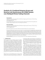
Example of chromatogram with interference between sodium and ammonium peaks. . . . . . . . . . . . . . . . . . . . . . . . . . . . . . . 10
4.1
4.2
Ammonium concentration over the nitrification unit. . . . . . . . .
Ammonium concentration into the denitrification and out of the OCR
unit over 24 hours. . . . . . . . . . . . . . . . . . . . . . . . . . . .
Denitrification and OCR unit. . . . . . . . . . . . . . . . . . . . . .
Series 1: Nitrate concentration as mgN O3 − N/l in and out of the
nitrification unit over 24 hours. . . . . . . . . . . . . . . . . . . . .
Series 1: Nitrate concentration as mgN O3 − N/l into the denitrification and out of the OCR unit over 24 hours. . . . . . . . . . . . . .
Nitrification test of the first nitrification tank. . . . . . . . . . . . .
Nitrification test of the last nitrification tank. . . . . . . . . . . . .
Nitrification test of the OCR tank. . . . . . . . . . . . . . . . . . .
Pictures taken of the biofilter media from aerobic tanks. . . . . . .
Denitrification test of the denitrification tank with biofilter media. .
Picture of biofilter media from the denitrification tank. . . . . . . .
Denitrification test of sludge from the denitrification tank. . . . . .
Denitrification test of sludge from the pump sump. . . . . . . . . .
Denitrification test of thick sludge from the pump sump. . . . . . .
The sum of nitrate and nitrite from the denitrification tests of the
pump sump . . . . . . . . . . . . . . . . . . . . . . . . . . . . . . .
Total organic carbon concentration as mg/l over 24 hours . . . . . .
COD . . . . . . . . . . . . . . . . . . . . . . . . . . . . . . . . . . .
BOD . . . . . . . . . . . . . . . . . . . . . . . . . . . . . . . . . . .
Common structure of the flocks in the water going to the fish. . . .
Characteristics of process water. . . . . . . . . . . . . . . . . . . . .
Higher organisms in the flocks. . . . . . . . . . . . . . . . . . . . . .
The pictures shows how the same amoebae changes its form. . . . .
Two different specimen of actinopodas. . . . . . . . . . . . . . . . .
Two different examples of rotifiers. . . . . . . . . . . . . . . . . . .
Unknown structures found in the sludge samples. . . . . . . . . . .
4.3
4.4
4.5
4.6
4.7
4.8
4.9
4.10
4.11
4.12
4.13
4.14
4.15
4.16
4.17
4.18
4.19
4.20
4.21
4.22
4.23
4.24
4.25
i
. 18
. 18
. 19
. 20
.
.
.
.
.
.
.
.
.
.
20
21
22
22
23
24
24
25
26
26
.
.
.
.
.
.
.
.
.
.
.
27
28
28
29
30
30
31
32
32
33
34
xi
List of Figures
xii
List of Tables
1.1
1.2
1.3
4.1
4.2
4.3
4.4
4.5
Dimensions of tanks . . . . . . . . . . . . . . . . . . . . . . . . . . .
Components of studied RAS at Lantfisk . . . . . . . . . . . . . . . .
Average retention times. Since there are three parallel lines for DN
and OCR the total retention time is shown for a single line. Fish
tanks are also connected in parallel and retention time is given as the
average for a single tank . . . . . . . . . . . . . . . . . . . . . . . . .
Nitrogen excretion based on feed rate during the series. The concentration increase is based on the volume of the entire system. . . . .
Rate of nitrification, NF1: First nitrification tank, NF5: last nitrification tank, L14: First OCR tank. . . . . . . . . . . . . . . . . . .
Rate of denitrification. . . . . . . . . . . . . . . . . . . . . . . . . .
Concentrations of metals (mg/kg dry matter) . . . . . . . . . . . .
Weights of dry sludge samples . . . . . . . . . . . . . . . . . . . . .
3
4
4
. 17
.
.
.
.
23
27
35
35
xiii
List of Tables
xiv
1
Introduction
1.1
Fish production
The fish production, both aquaculture and capture production, has grown significantly since the 1950’s and must grow further to satisfy the increasing global population and consumption. In 2013, the total fish production reached a number of
162.9 million tonnes of which 141.5 million tonnes was used for human consumption.
The estimated global annual fish consumption per capita has increased from 9.9 kg
in the 1960s to 14.4 kg in the 1990s to 19.7 kg in 2013. This is partly because of
increasing production of fish but also due to better distribution to consumers and
better utilization of the product, which reduces waste. This fast increase of fish production demands sustainable strategies and techniques for fishing that take social,
economical and environmental aspects into consideration[2].
At some places around the world, the capture fisheries production has reached a
point where it risks extinction of local fish stocks. This could in turn lead to disruption of ecosystems and devastate the subsistence for people who depend on fishing.
However, improvements of the of the fisheries management has led to small amends
in the state of some fish stocks. The increased growth in aquaculture stands for
almost half of the human consumption of fish. The most common method for traditional fish farming is in open cage systems in the ocean or in lakes. Large fish
cages are placed in already existent lakes or in the ocean where they utilize the surrounding ecosystem for water flow into the system and transport of faeces and food
waste out of the system. This is a cost effective and well established method but it
also causes strain on the ecosystem because of the nutrients and particles spread to
the local environment. There is also a risk of spreading disease and escape of fish,
which could disrupt the already existing ecosystem[2].
1.1.1
Recirculating aquaculture systems RAS
Semi-closed or closed systems have been developed to reduce the environmental impact of the open cage systems. This technique for fish farming can also be placed
in lakes or in the ocean. Water is pumped into a closed container with fish, which
can be a “moving bag” or a solid tank, and the water flows out from the container
at specific outlets. The water is then processed in a water treatment plant and can
be returned to surrounding water or a closed container for the fish[1].
1
1. Introduction
One method of fish farming that gives better control of the water treatment process
is RAS, recirculated aquaculture system. It is a land based process that implements
biological water treatment processes that removes nitrogen, biological matter and
phosphorus. This enables a high degree of water to be recirculated and reused in
the fish tanks. Nitrogen removal is important since the fish excrete ammonia from
their gills and ammonia is toxic to the fish at high concentrations. Nitrogen removal
is achieved by the processes called nitrification and denitrification, which is further
explained in section 2.1. The sludge produced in the process can be removed and sent
to sewage treatment or used as fertilizer. Compared to open cage system, RAS has
many advantages, such as reduction of pathogenic bacteria and disease, low water
use and high control of operational parameters. It also enables fish farming in areas
where the access to water is poor. On the other hand, it is an expensive process,
both in investment cost and in operational cost. It also requires close control by
experienced staff since the system is sensitive to changes in process parameters[1].
1.2
Lantfisk
Lantfisk is a small but expanding company on the outskirts of Gothenburg that
utilizes the RAS technique to farm Clarias gariepinus, also calles African sharptooth
catfish. They started their business in 2013 at a very small scale and in 2017
they produced 24 tonnes of fish. In 2018 they are planning on expanding their
production even further and expect to produce 40 tonnes of fish. Since Lantfisk
aims at continuous expansion of their production they wish to gain further knowledge
about their RAS.
1.2.1
RAS at lantfisk
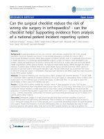
The flow chart of the RAS at Lantfisk is shown in Figure 1.1a. Floating feed is
provided with automatic feeders from 06:00 to 17:00. The tanks labeled NF and
OCR are aerated with pressurized air, which also cause agitation. The process is a
closed system, which means that all the water is recirculating within the system. It
is only refilled with water that corresponds to the loss of evaporation. More loops
than expected were found in the system. The loops have been introduced in order
to increase operating safety. Mainly the risk of overflow has decreased according to
Lantfisk. As is shown in Figure 1.1a water leaving Pump 2 can either pass through
the anoxic denitrification tanks (DN) and the aerated organic carbon removal tanks
(OCR), or pass directly to the OCR tanks. This bypass is introduced in order to
avoid overflow in the DN tanks while maintaining a high flow through the OCR
tanks in order to aerate the water to provide sufficient oxygen to the fish.
2
1. Introduction
(b) Flow through pumps
(a) RAS flow chart. DN=anaerobic tanks for deni-
trification, OCR=aerated tanks for organic carbon
removal, NF=aerated tanks for nitrification. The
number of tanks in series is also indicated for each
unit.
Pump 1
Pump 2
Pump 3
Flow (l/s)
2.0
2.1
8.2
The bioreactors used for the water treatment are filled with Kaldnes bio carriers in
order to provide sufficient area for microorganisms to grow. In the tanks labeled NF
and OCR in Figure 1.1a the bio carriers are moving around in the water as a result
of the aeration. The bio carriers in the tanks labeled DN are stationary because the
these tanks are filled with more carriers than the others, the flow is lower and there
is no aeration. This effectively turns these tanks into fixed bed bio reactors. The
water treatment of RAS is discussed further in section 2.1
Since Pump 3 has a higher flow than Pump 2 most of the water from the fish is
recirculated back through the pump sumps and does not reach the treatment. All
the tanks, including the pump sumps has the same dimensions, see Table 1.1. In
Table 1.2 the components of the system is listed.
Table 1.1: Dimensions of tanks
Height (m)
1
Length (m)
1.2
Width (m) Volume (m3 )
1
1.2
3
1. Introduction
Table 1.2: Components of studied RAS at Lantfisk
Number of units
(n)
Average water level
in units (m)
Total volume
in units (m3 )
Ratio of
component to
entire system (%)
Fish tanks
Anaerobic tanks
Aerobic tanks
Pump sump
Total RAS
20
9
11
4
44
0.81
0.75
0.69
0.58
-
24
10.8
13.2
4.8
52.8
45.5
20.5
25.0
9.1
100
Retention times in different tanks are calculated according to Equation 2.4. The
retention time vary between the units and is shown as averages in Table 1.3. Since
the denitrifying tanks are not agitated the hydraulic retention time is not a good
approximation of the residence time. However, the flow rate is 3-4 times lower into
the denitrifying tanks than into the OCR tanks.
Table 1.3: Average retention times. Since there are three parallel lines for DN
and OCR the total retention time is shown for a single line. Fish tanks are also
connected in parallel and retention time is given as the average for a single tank
Individual tanks (min) Total (min)
Nitrification
5,9
30,0
Organic carbon removal 13,2
26,4
Fish tanks
33,5
There is no dedicated unit for removal of solids and most of the solids are trapped
in the denitrification tanks where the flow is lowest and there is no agitation. These
tanks fill up with solids and are therefore emptied approximately once a month.
Solids also settle in the pump sumps. This creates anoxic environments where
denitrification can occur both in the denitrification tanks and in the pump sumps.
1.3
Research questions
The following are research questions that this project was aiming to answer.
1.3.1
What is the nitrogen removal rate?
The fish excrete ammonium which is toxic and has to be removed in a recirculating
system. The removal rates of ammonium and nitrate have therefore been studied.
4
1. Introduction
1.3.2
Are there daily variations of nitrogen compounds in
the system?
The fish is only fed during parts of the day. This could for example result in lower
concentrations of waste in the morning than at night.
1.3.3
What is the amount of dissolved carbon in the system
and how much of it is biodegradable?
The amount of dissolved carbon in the water was expected to be high in the entire
system because the water has a brown colour. The majority of the dissolved carbon
is also expected to not be digestible by the microorganisms. An aim has therefore
been to determine the amount of carbon in the system, and if it is biodegradable.
1.3.4
Is it viable to operate a RAS without a dedicated
sludge removal unit?
The system has no dedicated sludge removal unit. Instead sludge builds up in the
denitrification tanks where the flow is low and there is no agitation. When there
is too much sludge in the denitrification tanks they are emptied and are therefore
used for both sludge removal and denitrification.
5
1. Introduction
6
2
Theory
2.1
Water treatment in RAS
An efficient water treatment process is crucial for RAS. Ammonium should be kept
at a level below 45 mgN H4 − N/l and nitrate below 140 mgN O3 − N/l in order
to avoid disturbances in physiology, growth and feed intake [16][8].There are several
different RAS setups for fish production and the one that Lantfisk based their system
on is shown in Figure 2.1.
Figure 2.1: Theoretical RAS setup.
The conventional RAS configuration uses nitrifying biofilters to reduce ammonia and
nitrite concentrations by oxidizing them into nitrate. This is combined with organic
carbon removal where organic matter remaining after denitrification is removed by
heterotrophic bacteria in aerobic tanks. The sludge created in this process can be
removed by sedimentation or mechanical filtration [3]. The nitrification is carried
out by ammonia oxidizing bacteria (AOB) and nitrite oxidizing bacteria (NOB) in
aerobic tanks according to the following reactions 2.1 and 2.2. These bacteria are
autotrophic and can be outcompeted by heterotrophs. The presence of organic carbon can therefore reduce the effectiveness of the nitrification units[7]. The ratio of
carbon to nitrogen will affect which species are favoured. Especially the amount of
biodegradable carbon is of interest. The ratio of biological oxygen demand (BOD)
to total ammonia nitrogen (TAN) is used in this report. In order to avoid negative
effects on the nitrification rate the nitrification unit is placed after the organic carbon removal unit.
Nitrification:
2N H4+ + 3O2
2N O2− + 4H + + 4H2 O
2N O2− + O2
2N O3−
(2.1)
(2.2)
Ammonia and nitrite are toxic for aquatic animals while nitrate is much less harmful.
Consequently, priorities have been on removal of ammonia and nitrite. The nitrate
7
2. Theory
produced is normally removed in two ways, by dilution with water exchange or by
denitrification. In the denitrification, nitrate is reduced to nitrogen gas by oxidation
of organic matter and is emitted to the surrounding air according to equation 2.3.
Denitrification was introduced in order to increase the nitrate control and lower
the water exchange rate. In cases when the denitrification does not match the
nitrification the maximum allowed nitrate concentration steers the external water
exchange rate in the system. The conventional semi-closed RASs have a varying
external water exchange rate between 0.1-1m3 /kg feed to avoid accumulation of
nitrate. This corresponds to a water renewal of 5-10% of the system volume [3, 4].
Denitrification:
(2.3)
N O3− → N O2− → N O → N2 O → N2
The denitrifiction occurs at anaerobic conditions by facultative bacteria. The facultative bacteria are using electron donors originated from organic or inorganic sources.
In RAS and traditional wastewater treatment plants, heterotrophic denitrification is
the most commonly applied method. It uses organic electron donors from a carbon
source (e.g. carbohydrates, organic alcohols) that can be added externally to the
system or originate from the fish feed or faeces. If the process has limited access to a
biodegradable carbon source, accumulations of intermediate products, such as NO2
and N2 O, can occur. If the process has an excess of carbon, the concentration of
ammonia could increase due to AOB being outcompeted by heterotropic bacteria[3].
By reducing the concentration of nitrate, the need for water exchange will be lowered and thus decrease the water use of the process. Apart from the direct toxic
effect from high nitrate concentrations on aquatic animals, there are regulations on
how much nitrate that is allowed to be discharged. Since the denitrification reduces
the nitrate levels and thereby the water use, these restrictions are more easily attained and increase the sustainability of the RAS [3]. Another positive effect of
denitrification is improved alkalinity. The intensive nitrification of RAS leads to a
decreased alkalinity and a resulting drop in pH. Acidic conditions negatively affects
the performance of the biofilter and the environment for the aquatic organisms. Alkalinity supplements, usually sodium bicarbonate, are commonly added to stabilize
the alkalinity and pH. By incorporating heterotrophic denitrification the alkalinity
will be increased and thus the need for alkalinity supplement will be reduced or even
eliminated[3]. There is also a risk with a low water exchange rate. When much of
the same water is used in the process, accumulation of growth inhibiting substances
may occur. These substances come from the fish, bacteria or the food and cannot
be degraded by the water treatment processes. Examples of these substances are
cortisol, a stress hormone from the fish, or metals that are brought to the process
by the feed[4].
After the denitrifying units the water is transported to aerated tanks for organic
carbon removal. In these tanks organic material is consumed by bacteria and carbon
dioxide is released. The tanks for denitrification and organic carbon removal are
connected in series.
8
2. Theory
2.2
Ion chromatography
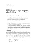
Ion chromatography was used in order to determine concentrations of the nitrogen
containing ions in the system. However, there are disproportionate concentrations
of ammonium and sodium in this system and since they have similar retention times
that causes interference. In Figure 2.2a and 2.2b there is an example of a chromatogram where this can be seen. This is common when there are disproportionate
concentrations of sodium and ammonium, but by using different equipment better separation of the peaks can be achieved[10]. This was not in the scope of the
project and this source of error in determining ammonium concentration could not
be avoided.
9
2. Theory
(a) Chromatogram of sample before nitrification unit.
(b) Close up of ammonium peak close to sodium peak.
Figure 2.2: Example of chromatogram with interference between sodium and ammonium peaks.
2.3
Carbon removal
As mentioned in Section 2.1, carbon is required for denitrification but undesirable
in nitrification. No external carbon source apart from the fish feed is used in the
10
2. Theory
studied RAS. In order to determine the amount of carbon present in the system the
total organic carbon (TOC) was measured. Samples were taken so that the change
in concentration over the different treatment units could be determined. In order to
find out how much of that carbon that could be utilized by the microorganisms biological oxygen demand (BOD) and chemical oxygen demand (COD) were analyzed.
BOD is a measurement of how much oxygen is consumed by microorganisms in a
sample over a specified time. BOD7, for example is the consumption over seven days
which was used in this case. This can be compared to COD which is the oxygen
consumption when the content of a sample is oxidized chemically[15].
2.4
Flow
In order to estimate the residence time in the bioreactors the hydraulic retention
time (HRT) was calculated using the relation:
HRT = V olume of tank/Inlet f low rate
(2.4)
Using the residence time along with concentrations from the flow to and out of the
reactor the reaction rate can be estimated using:
Reaction rate = (Cin − Cout )/HRT
2.5
(2.5)
Excretion
As mentioned in section 1.1.1 fish excrete ammonium. However they only do this
when they have been fed. When they are being fed the excretion rate increase
and when the feeding stops the excretion decline over time. Approximately five
hours after feeding ceased the ammonia production was undetectable in a study by
Bovendeur et al.[9]. The excretion rate of total ammonia nitrogen is estimated to
be 3% of the daily feeding rate[7].
11