SUBJECT MICROFLUIDICS
Bạn đang xem bản rút gọn của tài liệu. Xem và tải ngay bản đầy đủ của tài liệu tại đây (1.8 MB, 22 trang )
Vietnam National University Ho Chi Minh City
University of Science
FACULTY OF MATERIALS SCIENCE & TECHNOLOGY
Instructor D.Sc LE VIET HAI
GROUP 4
NGUYEN THI HONG YEN 1619302
SEMINAR SUBJECT: BIOSENSES
TOPIC: MICROFLUIDICS
NGUYEN NHAT XUAN AN 1619001
Insert image of colony flower
Insert image of colony tree
BASIC CONCEPTS IN
MICROFLUIDICS
MICROFLUIDIC TECHNOLOGY:
Insert image of colony bird
HOW TO BUILD A MICROFLUIDIC
CHIP
CHAPTER I
THE STRUCTURE AND
OPERATION MECHANISM OF
MICROFLUIDICS
CHAPTER III
Insert image of famous person
CHAPTER II
APPLICATIONS OF MICROFLUIDICS
CONTENTS
CHAPTER IV
1.1. The development of microfluidics
In the early 1990ies, The field of lab-on-a-chip systems has evolved dramatically.
The main vision being to develop entire bio/chemical laboratories on the surface of silicon or polymer
chips.
Polymer-based lab-on-a-chip systems have emerged the recent years, and these systems promise
CHAPTER I: BASIC CONCEPTS
cheaper and faster production cycles. The study of fluid motion in microsystems is denoted
IN MICROFLUIDICS
microfluidics.
1.2. Definitions
Microfluidics
The science which studies the behavior of fluids through micro-channels and the technology of
manufacturing microminiaturized devices containing chambers and tunnels through which fluids flows
or are confined
CHAPTER I: BASIC CONCEPTS
IN MICROFLUIDICS
Deal with very small volumes of fluids (fL)
1.2. Definitions
A microfluidic chip
A pattern of micro-channels, molded or engraved
This network of micro-channels incorporated into the microfluidic chip is linked to the macro-environment by several
CHAPTER I: BASIC CONCEPTS
holes of different dimensions hollowed out through the chip. It is through these pathways that fluids are injected into
IN MICROFLUIDICS
and evacuated from the microfluidic chip.
A microfluidic chip is a device that enables a tiny amount of liquid to be processed or visualized. The chip is usually
transparent and its length or width are from 1cm (0.5″) to 10cm (4″). The chip thickness ranges from about 0.5mm
(1/64″) to 5mm (1/4″).
1.1. Structure
A microfluidic chip is a set of micro-channels etched or molded into a material (glass, silicon or polymer such as PDMS, for
Poly Dimethyl Siloxane). They are connected together in order to achieve the desired features (mix, pump, sort, or control
the biochemical environment).
CHAPTER II:
THE STRUCTUREAND
OPERATION MECHANISM OF
MICROFLUIDICS
This network of micro-channels trapped into the microfluidic chip is connected to the outside by inputs and outputs pierced
through the chip, as an interface between the macro- and micro-world.
It is through these holes that the liquids (or gases) are injected and removed from the microfluidic chip (through the tubing,
syringe adapters or even simple holes in the chip) with external active systems (pressure controller, push-syringe or
peristaltic pump) or passive ways (e.g. hydrostatic pressure).
1.2. How does microfluidics work?
Microfluidics systems work by using a pump and a chip. Different types of pump precisely move liquid
inside the chip with the rate of 1 μL/minute to 10,000 μL/minute). Inside the chip, there are microchannels that allow the processing of the liquid such as mixing, chemical or physical reactions. The
CHAPTER II:
THE STRUCTUREAND
OPERATION MECHANISM OF
MICROFLUIDICS
liquid may carry tiny particles such as cells or nanoparticles. The microfluidic device enables the
processing of these particles, for example, trapping and collection of cancer cells from normal cells in
the blood.
1.1. Fabrication materials
The materials make it possible to design microfluidic chips with new features like specific optical characteristics, biological
or chemical compatibility, faster prototyping or lower production costs, the possibility of electro sensing, etc. The final
choice depends on the application.
Polymers (e.g. PDMS), ceramics (e.g. glass), semiconductors (e.g. silicon) and metal
chapterIII: MICROFLUIDIC
Nowadays, a lot of researchers use PDMS and soft lithography due to their easiness of use and fast process. They allow
TECHNOLOGY: HOWTO BUILD A
researchers to rapidly build prototypes and test their applications/setups, instead of wasting time in laborious fabrication
MICROFLUIDIC CHIP
protocols.
1.2. The fabrication of a simple microfluidic chip requires several steps
The design of microfluidic channels with dedicated software (AUTOCAD, Illustrator, LEDIT…)
Transferred on a photomask: chrome coated glass plates or plastic films for the most common templates. (dedicated
manufacturers or in a clean room for glass masks)
The micro-channels are printed with UV opaque ink (if the substrate is a plastic film) or etched in chromium (if the substrate
is a glass plate).
chapterIII: MICROFLUIDIC
TECHNOLOGY: HOWTO BUILD A
MICROFLUIDIC CHIP
chapterIII: MICROFLUIDIC
1.3. The fabrication of microfluidic mold by photolithography
TECHNOLOGY: HOWTO BUILD A
MICROFLUIDIC CHIP
(1) Resin is spread on a flat surface (often a silicon wafer) with the desired thickness (which
determines the height of microfluidic channels)
(2) The resin, protected by the photomask with the microchannel pattern, is then partially
exposed to UV light.
(3) The mold is developed in a solvent that etches the areas of resin that were not exposed to UV
light.
(4) We obtain a microfluidic mold with a resin replica of the patterns from the photomask (future
micro-channels make “reliefs” on the mold).
chapterIII: MICROFLUIDIC
1.4. The molding of microfluidic chips:
TECHNOLOGY: HOWTO BUILD A
MICROFLUIDIC CHIP
(1) The molding step allows mass production of microfluidic chips from a mold.
(2) A mixture of PDMS (liquid) and cross-linking agent (to cure the PDMS) is poured into the mold and heated at a high
temperature.
(3) Once the PDMS is hardened, it can be taken off the mold. We obtain a replica of the micro-channels on the PDMS block.
Microfluidic device completion:
(4) To allow the injection of fluids for future experiments, the inputs and outputs of the microfluidic device are punched with
a PDMS puncher of the size of future connection tubes.
(5) Finally, the face of the block of PDMS with micro-channels and the glass slide are treated with plasma.
(6) The plasma treatment allows PDMS and glass bonding to close the microfluidic chip.
chapterIII: MICROFLUIDIC
TECHNOLOGY: HOWTO BUILD A
1.5. Integration of complex functions:
MICROFLUIDIC CHIP
Many microfluidic devices incorporate other features that require the integration
of electrodes, nanostructures or surface functionalization. This type of additional
steps uses generally standard techniques of micro and nanotechnology (thin film
deposition, plasma etching, self-assembled monolayers).
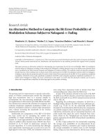
1.1. Glucose biosensor based on open-source wireless microfluidic potentiostat
1.1.1. Structure.
CHAPTER IV:APPLICATIONS
OF MICROFLUIDICS
Figure : Simplified schematic of automated microuidic wireless potentiostat
system: (A) carbon electrode, (B) PEGDGE, (C) MWCNTs, (D) Os(bpy)PVI,
(E) FADGDH, (F) wireless potentiostat, (G) wireless data transfer to internet
based server, (H) data viewed using in
Glucose biosensor
1.1.2. Priciple:
Automate liquid flow and direction include a report
The driving force is supplied by compressed nitrogen,
Integrate automated microfluidic flow and direction
by on a Bluetooth enabled microfluidic liquid
via desktop computer for a multiplexed photonic
with the iMED
handling system that utilized a microcontroller,
crystal.
solenoid valves, and pneumatic pressure.
Priciples of IMED operation:
The entire iMED platform is designed to operate without a desktop computer.
The iMED uses over the air updates (OTA) mechanism which allows the potentiostat to update itself based on
data received while the normal firmware is running (for example, over WiFi) .
The use of the iMED using an electrochemical enzyme-amplified biosensor.
1.1.3. Application:
The extraction of nucleic acids rotating disc based analysis of infectious disease, flow cytometry, magnetic
stirring, genetic stability with multiplexed PCR, chemiluminescence detection and protein immunoblotting.
Detection of glucose concentrations in solution.
The system capability was demonstrated by application to a bead-based HIV1 p24 sandwich immunoassay on a
multi-layer polydimethylsiloxane (PDMS) chip .
Glucose biosensor
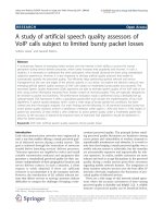
1.2. Detection of cancer antigens (CA-125) using gold nano particles on interdigitated electrode-based microfuidic
biosensor:
1.2.1. Structure:
The interdigitated electrodes were patterned using a photolithography process .
A silicon wafer with an oxide layer was used as the substrate .
A positive tone photoresist .
A gold layer 95 nm thick was deposited on top of the Titanium coated silicon substrate using high vacuum e-beam
metal evaporator .
CHAPTER IV:APPLICATIONS
OFMICROFLUIDICS
Figure : AFM image of the plain electrodes
1.2.2. Priciples :
The antigen detection under shear flow condition during self-driven flow of antigen solution, when immobilized with the gold nano
particles (GNPs) .
The capacitive signal response of the gold nano particle coated interdigitated electrodes compared to the plain interdigitated electrodes
during the antigen–antibody.
The biosensor was exposed to CA-125 antigens in both the static and microfluidic flow conditions.
Detection of cancer
antigens
Figure : Schematic representation at various stages of biosensor fabrication: (i) Bare electrodes (ii) SAM layer on the bare electrodes (iii)
immobilized gold nano particles on the SAM layer (iv) Antibody immobilization on the electrodes (v) antigen–antibody con
1.2.3. Application
The feasibility of expanding the sensor to multiplex assay to detect the panel of protein biomarkers that minimize
the false positive and false negative scenarios in cancer diagnosis which commonly arise from measuring a single
biomarker.
Detection of cancer
antigens
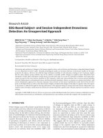
1.3. A microfluidic biosensor using graphene oxide and aptamerfunctionalized quantum dots for peanut
allergen detection:
1.3.1. Structure:
The Ara h 1 aptamer synthesis.
80 base pairs sequence:
5′TCGCACATTCCGCTTCTACCGGGGGGGTCGAGCGAGTGAGCGAATCTGTGGGTGGGCCGTA
AGTCCGTGGTG CGAA 3′(the 5′ end was modified with biotin).
CHAPTER IV:APPLICATIONS OF
MICROFLUIDICS
Ara h 1, Ara h 2, Ara h 3 standards.
The Ara h 1 ELISA kit.
CdSe Qdots modified with covalently attached streptavidin.
Polydimethylsiloxane.
Graphene oxide.
Phosphate-buffered saline (PBS).
Chemicals and solvents.
1.3.2. Priciple:
The fluorescence quenching and recovering properties of GO through the adsorption and desorption of QDots-conjugated
aptamers .
The fluorescence signals were measured on a miniaturized optical detector .
Fluorescence of Qdots is quenched via FRET process between the Qdots-aptamer probes and GO due to their selfassembly through specific π–π interaction.
A microfluidic
biosensor
Figure : (A) Schematic of the sensing mechanism of the Qdots-aptamer-GO quenching system. (B) Schematic diagram of microfluidic chip design (not to scale). The
microfluidic chip had two inlets for loading the Qdots-aptamer-GO probe mixture and the Ara h1 sample.
1.3.3. Application:
A microfluidic system integrated with a quantum dots (Qdots) aptamer functionalized graphene oxide (GO)
nano-biosensor for simple, rapid, and sensitive food allergen detection.
Quantitative detection of Ara h 1, one of the major allergens appearing in peanuts.
A microfluidic
biosensor
THANK YOU