đức anh đề cương máy điện
Bạn đang xem bản rút gọn của tài liệu. Xem và tải ngay bản đầy đủ của tài liệu tại đây (568.9 KB, 23 trang )
1.a) What are the requirements of dc machine's armature windings?
b) Define the winding pitches, collector's segment and pole pitch?
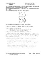
c) Draw a figure of the winding pitches in case of simplex lap winding?
2: present the main and linkage flux in DC machine?
3 : Present the distributon of magnetic field on the armature surface when the
brush is on the geometrical neutral axis and the main magnetic field is not
considered.
4 : What is the armature magnetic field? Present the cause of spark in the armature
winding of DC machine?
5 : Present the method of improving the reversing direction rectification in DC
machineby using the auxiliary magnetic pole ?
6. Establish the magnetomotive force equations of the transformer?
7) What are the reasons and conditions for establishing a replacement circuit of a
transformer? Draw the equivalent circuit of transformer and explain the
parameters?
8. draw an open circuit experiment diagram and introduce the pitch to determine
the magnetizing circuit parameter of the transformer
9. Draw a short - circuited experiment diagram and introduce the pitches to
determine the primary and secondary circuit impedance of the transformer?
10: write the basic set of equations of an asynchronous machine in the case of a
rotating rotor .Draw the vector graph ?
11) write the basic set of equations of an asynchronous machine in the case of a
rotating rotor? Draw the vector graph in motor mode and generator mode.
12. Establish the equivalent circuit of induction machines in case of stationary
rotor ?
13 : Draw the equivalent circuit of induction machines in the case of rotating
rotors. Draw a vector diagram in motor mode.
14 : What is an amature reaction of synchronous machine? Which does it depend
on? Which are the properties of amature reaction when working with capacitive
load?
15: establish the equivalent voltage equation of syn.machine? in case of
unsaturated magnetic circuit, draw the vector diagram of synchronous generator
salient pole? What’s comments from the vector graph?
16. A) Establish the active power-angle equation of synchronous machine,
B) draw curve of this power-angle characteristic?
1.a) What are the requirements of dc machine's armature windings?
b) Define the winding pitches, collector's segment and pole pitch?
c) Draw a figure of the winding pitches in case of simplex lap winding?
a) Requirements for winding:
- generate the necessary electromotive force such as: a passant current which
produce the required torque, do not give the overheating.
- ensure for a good changement of direction
- have a simple, sure are safe structure
b)
+) Pitches of winding
-The first winding pitch y1: is the distance between the first
working-edge and the second working -edge of one
winding element
- Second winding pitch y2: is the distance between the
second working-edge of the fist winding element and the
fist working-edge of the second wingding element
-The mix winding pitch: is the distance between two fist
working-edge of two adjacent elements
-The collector pitch yg=: is the distance between to
winding-edge of one winding element.
Y1=
Y=YG=1
Y2=Y1-YG
c)
Uniform winding element
Level winding element
2: present the main and linkage flux in DC machine?
The main flux � 0 pass through the airgap between
induced part and pole within one pole step
�� is scattered flux:
The magnetic flux linking the loop separately to each winding is called the flux
magnetic flux, we have the stator magnetic flux, the only stator loops with the
stator winding, the rotor flux magnetic floss loops with the rotor winding only.
Dissipation flux is characterized by dissipation resistance.
3 : Present the distributon of magnetic field on the armature surface when the
brush is on the geometrical neutral axis and the main magnetic field is not
considered.
-
If N is the total number conductor of the winding , the number ampere
conductor per unit length equival
A= N
iu
πD
iu =
( A/cm) With
i
2a
is the current in conductor
D is the outer diameter of the armature (cm)
A is the number of branched part
-
If the circuit is symetrical with the midpoint of two brushes, according to the
law of total current, the magnetomotive force of armature part at a point x is
Fux = A.2.x
-
(A/pair of pole)
If bypassing the magnetic impedance of magnetic poles of the terminals and
rotors,
Fux
distance
δ
is the magnetic force required to force the path through the two
is
Fuwx = H uwx .2δ
The word bromide in the opening will be
-
Bux = µ0 H ux = µ0
with
µ0
H ux
Fux
A
= µ0 x
2δ
δ
is magnetic field magnitude at the base of a segment
x
is permeability of air
4 : What is the armature magnetic field? Present the cause of spark in the armature
winding of DC machine?
•
•
-
In order to produced magnetic field of armature part, we introduc DC current
in to the armature part by the brush as normal working condition
The cause of spark
Mecanical cause
+ Collector is not consistant with the central axis
+ Rotating part is not well balenced
+ The surface of collector is not flat
+ Force on brush is inappropriate
-
Electromagnetic force
+ The reactant of electromotive force does not remove completely the reversing
electromotive force
+ The current’s distribation on the contact surface is not uniform
5 : Present the method of improving the reversing direction rectification in DC
machineby using the auxiliary magnetic pole ?
1)
2)
The fandaneted way to impove the reversing dỉrection is to create an extural
magnetic field also knows as a reversig magnetic field at neutral zone by
placing auxiliary pole between the main pole.
The magnetomotive force ( emf ) of auxiliary pole Ft must be :
a) Direction ,inverse with horizonal emf of induced part Fuq .
b) Magnitude have to neutrualize the effect of Fuq and also create the
auxiliary field to genenate the reversing emf epk .
Therefore ,the auxiliary pole in the generator must be set to have do same
polarity as the main pole with the egles of the winding elememt at the
auxiliary pole appwatching inverseinthe motor mode.
d) Due to the reactant emf epk=Iu and edc is proportial with Bdc ,so Bdc have
to be ratio with Iu.
e) Therefore , auxiliary pole winding must be connected part winding and Iu
is changed only is a zone that auxiliary polr circuit is not saturated.
The air gap between auxiliary pole and induced part =( 1,5 - 2 ) time the main
pole and induced part gap . The width of auxiliary pole =( 0,4 – 0,8 ) time the
width of reversing director zone.
The auxiliary pole is only located on machine with P > 0,3 KW ,munber of
auxiliary pole = number of main pole.
c)
3)
4)
6.
Establish the magnetomotive force equations of the transformer?
With load : I1W1+I2W2
Open circuit : I0W1
Because the applied voltage in primary winding U1=Udm=const
m = const
So, the balance magnetomotive force equations is obtained as follow:
I1W1+I2W2 = I0W1
Complex form
W1+2W2 = 0W1
1
Where
2
=0+(-2 )
=0 + (-2’)
’= 2
- When the transformers works with load the total magnemotive force
(i1.w1+i2.w2) of the primary and secondary winding generated the main magnetic
flux in transformers.
- When the transformers works in the opens circuit case: the secondary winding is
opened the current in primary winding is i0, the magnemotive force i0.w1
produces the main magnetic flux in transformers.
7) What are the reasons and conditions for establishing a replacement circuit of a
transformer? Draw the equivalent circuit of transformer and explain the
parameters?
Reason: In order to simplify the transformation of transformer and power system,
we replace the electric circuit and magnetic circuit of transformer to an equivalent
circuit. This consist of resistance and reactance called an repalacement circuit of
transformer.
Condition: In the process of conversion. It makes sure that the physical and energy
process have not to change, such as transmission power, machine losses,etc…
The Equivalent Circuit of Transformer:
8. draw an open circuit experiment diagram and introduce the pitch to determine
the magnetizing circuit parameter of the transformer
open circuit experiment
open circuit in secondary winding
A
*
*
W
I0
U source
-the
V1
U20
primary winding is applied a voltage U1 = U1dm and the secondary winding is
open
I0 % = x 100%
R0 = =R1 + Rm ≈ Rm
Z0 = ≈ Zm
X0= Z02 – R02) ≈ Xm
I0 is the open circuit current
X0 is the open circuit reactance
Z0 is the open circuit inpedance
R0 is the open circuit resistance
Rm is magnetic resistance which prensent the main magnetic flux
Xm is magnetic reactance which prensent the main magnetic flux
Zm is magnetic inpedance which prensent the main magnetic flux
9. Draw a short - circuited experiment diagram and introduce the pitches to
determine the primary and secondary circuit impedance of the transformer?
- The secondary winding is shorted
Determine: Un, In, Pn
Zn=
- The primary winding is applied
a low voltage for obtaining I1n= I1dm
rn=r1+r2’= Pn/In2
- Based on meters , we
determine : Un , In , Pn
xn=
=> So , we calculate :
r1=r2’= rn/2 ; x1=x2’=xn/2
10: write the basic set of equations of an asynchronous machine in the case of a
rotating rotor .Draw the vector graph ?
U1= -E1+I1(r1+jx1)= -E1+I1* Z1
0=E’2 –I’2*(r’2/s +jx’2)=E’2 –I’2(x’2+jx’2+([1-s]/s)r’2
E’2 =E1
I1+I’2=I0
-E1=I0 (rm+jxm) =I0 *Zm
Where
U1, E1, I1: voltage,emf and current of stator winding
r1, x1, Z1: resistance, reactance and impedance of satator winding
E’2, I’2:emf and current of rotor winding which area converted to stator winding
r’2, x’2: resistance, rectane of rotor which are conveted to stator winding
s: coefficient of slide
rm: resitance of magnetic circuit which is characteristic for iron losses
xm:reactance of magnectic circuit which presents the mutual inductance between
stator and rotor
I0:current in magnectic circuit which produces the mmf F0
The vector graph
11) write the basic set of equations of an asynchronous machine in the case of a
rotating rotor? Draw the vector graph in motor mode and generator mode.
Emf : electromotive force
Mmf :magnetomotive force
U1=-E1+I1(r1+jx1)=- E1+ I1Z1
0=E2'- I2'(r'2+jx2')= E2'- I2'(r'2+jx2'+ r2')
E2'= E1
I1+ I2'= I0
-E1= I0(rm+jxm)= I0 Zm
Where:
U1, E1, I1: voltage, emf and current of stator winding
r1, x1, Z1: resistance, reactance and Impedance of stator winding
E'2, I'2 : emf and current of rotor winding which are converted to stator winding
r'2, x2' : resistance, reactance of rotor winding which are converted to stator
winding
s : coefficient of slide
rm : resistance of magnetic circuit which is characteristic for iron losses
xm :reactance of magnetic circuit which presents the mutal inductance between
stator and rotor
I0 : is current in magnetic circuit which produces the mmf F0
12. Establish the equivalent circuit of induction machines in case of stationary
rotor ?
-
-
When rotor is non-rotating : f2 = f1, so the voltage transform rotio :
Ke ==
Converting rotor emf to stator emf, we have:
E1= E2’ = KeE2
The equivalent emf equation in stator circuit
U1 =-E1 + I1 .(r1 + jx1 )= -E1 + I1Z1 = - (E1 + Eσ1 ) + I1.r1
Eσ1 : is dissipated emf induction in stator
I1r : is drop voltage in stator circuit
Z1=r1 + jx1 : is impedance of stator winding
-
Because rotor winding is shorted, the equivalent emf equation in rotor circuit
is:
0 = -E2 + I2 .( r2 + jx2 ) = -E2 + I2Z2
r2 : rotor resistance
x2: dissipated reactance in rotor winding
Z2: impedance of rotor winding
-
Similar to transformer, we have :
-E1 = I0 Zm = I0 ( rm + j xm )
rm : resistance of magnetic circuit which is characteristic for iron losses
Xm: reactance of magnetic circuit which produce the mmf F1
-
Converting the resistance due to losses is :m2I22 r2 = m1I2΄ 2 r2’
‘
r2 = kiker2=k.r2
Converting X2 due to the phase between F2 and I2 const :
Tan φ2 = =
X2’ = .x2 = k.x2
Impedance : Z2’= r2’ + jx2’ = k( r2 + jx2 )= k.Z2
-
K=kike : is converted ratio of resistance, reactance and
impedance
Conclusion: the final equation of induction machines in case of stationary rotor
U1 =-E1 + I1Z1 = -E1 + I1.(r1+jx1)
0 =E΄2 - I΄2.(r΄2+jx΄2) = -E΄2 + I΄2.Z΄2
E2’ = E1
I1 + I2’ = I0
-E1 = I0 Zm = I0 ( rm + j xm )
U1 E1 I1 : voltage, emf, current of stator winding
r1 , x1, z1 : resistance, reactance, impedance of stator winding
E΄2 + I΄2 emf and current of rotor winding which are converted to stator winding
r΄2, x΄2, Z΄2: resistance, reactance, impedance of rotor winding which are
converted to stator winding
rm: is resistance of magnetic circuit which is characteristic for iron losses
xm: is reactance of magnetic circuit which present the mutual inductance
between stator and rotor
I0: is current in magnetic circuit which produce the mmf Fo.
The equivalent circuit
When rotor is non-rotating ( stationary rotor ) and rotor winding is shorted, for
limiting the current I1 & I2 in stator winding and rotor winding to nominal value,
the applied voltage should be decreased → the electromotive force ( emf ) E1
decreases → the main flux in machine decrease → the magnetomotive force
( mmf ) F0 very small → ignore.
F1 + F2 = F0 ≈ 0 (1) → I1 + I2 (2)
With (1) & (2) we have:
I1 = U1/( Z1 + Z΄2 ) = U1 / Zn
Where: Zn = Z1 + Z΄2 = rn + jxn is short circuit impedance of IM
13 : Draw the equivalent circuit of induction machines in the case of rotating
rotors. Draw a vector diagram in motor mode.
14 : What is an amature reaction of synchronous machine? Which does it depend
on? Which are the properties of amature reaction when working with capacitive
load?
-
-
-
When a synchronous generator's rotor is spun, a voltage EA is induced in the
generator's stator windings. If a load is attached to the terminals ofthe
generator, a current flows. But a three-phase stator current flow will produce a
magnetic field of its own in the machine. This stator magnetic field distorts the
original rotor magnetic field, changing the resulting phase vo ltage. This effect
is called armature reaction because the armature (stator) current affects the
magnetic field which produced it in the first place.
In an alternator like all other synchronous machines, the effect of armature
reaction depends on the power factor i.e the phase relationship between the
terminal voltage and armature current.
The properties of armature reaction under capacitive load is to help the main
field flux and thereby increasing the electromagnetic force induced in the
armature. Therefore, when a synchronous generator is capacitively loaded, It’s
terminal voltage will increase.
15: establish the equivalent voltage equation of syn.machine? in case of
unsaturated magnetic circuit, draw the vector diagram of synchronous generator
salient pole? What’s comments from the vector graph?
•
Generator synchronous
With symmetric load, the equation of phase the voltage is as follows
U = E� – I(ru+jxσu) (1)
Where U: terminal voltage of generator
ru+jxσu : the resistance & the reactance of the armature winding
E� the emf of armature winding
•
In case of unsaturated magnetic circuit: E� = E + Eu
(2)
Combining the above two equations (1)&(2), we have:
U = E� +Eu– I(ru+jxσu)
Eu = -jIu U = E – j I(ru+jxσu) - I.ru = E – jIxdb - I.ru
Where: xdb = xu + xσu is the synchronous reactance of salient pole synchronous
generator.
Vector diagram of synchronous generator salient pole
Left – in case of inductive load
Right - in case of capacitive load
16. A) Establish the active power-angle equation of synchronous machine,
B) draw curve of this power-angle characteristic?
A) Active power –angle characteristic
-the active power-angle characteristic of synchronous machine is expressed by:
P=f (); when E= const, U= const
Where it the angle between to vectors of E and U
Ignoring rư since it is much smaller than Xđb, Xd
and X, we obtain
P=m.U.I.cos
a)in case of salient synchronous machine
according to the simplified vector diagram with Rư=0, we have:
Id=
Iq=
With:
So P= m.U.I.cos = m.U.I.cos () = m.U.(Icos.cos
= m.U.(Iq.cos + Id.sin)
Finally we have:
P=.sin+.(-).sin2
= PE+PU
Inper unit of machine (P.U)
P*=.sin+.( - ).sin2
b) in case of non-sqliend synchronous machine: P=.sin
B) Characteristic curve of power angle