IT training microcontroller projects in c for the 8051 ibrahim 2000 06 19
Bạn đang xem bản rút gọn của tài liệu. Xem và tải ngay bản đầy đủ của tài liệu tại đây (973.11 KB, 187 trang )
Microcontroller Projects in C
for the 8051
This
. Page Intentionally Left Blank
Microcontroller Projects
in C
for the 8051
Dogan Ibrahim
OXFORD AUCKLAND BOSTON JOHANNESBURG MELBOURNE NEW DELHI
Newnes
An imprint of Butterworth-Heinemann
Linacre House, Jordan Hill, Oxford OX2 8DP
225 Wildwood Avenue, Woburn, MA 01801-2041
A division of Reed Education and Professional Publishing Ltd
A member of the Reed Elsevier plc group
First published 2000
# Dogan Ibrahim 2000
All rights reserved. No part of this publication
may be reproduced in any material form (including
photocopying or storing in any medium by electronic
means and whether or not transiently or incidentally
to some other use of this publication) without the
written permission of the copyright holder except
in accordance with the provisions of the Copyright,
Designs and Patents Act 1988 or under the terms of a
licence issued by the Copyright Licensing Agency Ltd,
90 Tottenham Court Road, London, England W1P 9HE.
Application for the copyright holder's written permission
to reproduce any part of this publication should be addressed
to the publishers
British Library Cataloguing in Publication Data
A catalogue record for this book is available from the British Library
ISBN 0 7506 46403
Library of Congress Cataloguing in Publication Data
A catalogue record for this book is available from the Library of Congress
Tyeset by David Gregson Assciates, Beccles, Suolk
Printed and bound in Great Britain
Contents
vii
Preface
Chapter 1
1.1
1.2
1.3
1.4
1.5
1.6
1.7
1.8
1.9
1.10
Introduction
Microcontroller Evolution
Microcontroller Architecture
8051 Family
Architecture of the 8051 Family
Pin Con®guration
Timer/Counters
Interrupt Control
Minimum Microcontroller Con®guration
Project Development
Chapter 2
2.1
2.2
2.3
2.4
2.5
Microcomputer Systems
Programming Microcontrollers in C
Data Types
2.1.1 bit
2.1.2 signed char/unsigned char
2.1.3 signed short/unsigned short
2.1.4 signed int/unsigned int
2.1.5 signed long/unsigned long
2.1.6 ¯oat
2.1.7 sbit
2.1.8 sfr
2.1.9 sfr16
Memory Models
Interrupts
Structure of a Microcontroller-based C Program
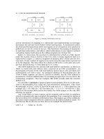
Program Description Language
2.5.1 START-END
2.5.2 Sequencing
2.5.3 IF-THEN-ELSE-ENDIF
1
1
1
2
3
4
4
10
11
12
13
15
16
16
16
17
17
18
18
18
19
19
19
20
21
22
22
24
24
vi
Microcontroller Projects in C for the 8051
2.6
2.7
2.5.4 DO-ENDO
2.5.5 REPEAT-UNTIL
Internet Web Sites of Microcontroller Compilers
Further Reading
24
25
25
27
Chapter 3
PROJECT
PROJECT
PROJECT
PROJECT
PROJECT
PROJECT
PROJECT
PROJECT
PROJECT
PROJECT
PROJECT
Light Projects
1 ± LED Binary Counter
2 ± LED Chasing Circuit
3 ± Random LED Pattern
4 ± Cyclic LED Pattern
5 ± LED Dice
6 ± Hexadecimal Display
7 ± Two-digit Decimal Count
8 ± TIL311 Dice
9 ± 7 Segment Display Driver
10 ± Four-digit LED Display Interface
11 ± Interrupt Driven Event Counter with 4-digit
LED Display
29
29
33
34
37
38
46
50
53
57
62
75
Chapter 4
Sound Projects
85
PROJECT 12 ± Simple Buzzer Interface
PROJECT 13 ± Small Speaker Interface (Using the Timer Interrupt)
PROJECT 14 ± Two-tone Small Speaker Interface
(Using the Timer Interrupt)
PROJECT 15 ± Electronic Siren (Using the Timer Interrupt)
PROJECT 16 ± Electronic Siren (Using the Timer Interrupt)
95
101
Chapter 5
107
Temperature Projects
86
90
94
PROJECT 17 ± Using a Digital Temperature Sensor
PROJECT 18 ± Digital Thermometer with Centigrade/Fahrenheit
Output
PROJECT 19 ± Digital Thermometer with High Alarm Output
PROJECT 20 ± Digital Thermometer with High and Low Alarm
Outputs
PROJECT 21 ± Using Analogue Temperature Sensor IC with A/D
Converter
125
126
Chapter 6
147
RS232 Serial Communication Projects
108
119
132
PROJECT 22 ± Output a Simple Text Message from the RS232 Port
PROJECT 23 ± Input/Output Example Using the RS232 Port
PROJECT 24 ± A Simple Calculator Program Using the RS232 Port
151
155
161
Appendix ± ASCII code
167
GLOSSARY
171
Index
177
Preface
A microcontroller is a single chip microprocessor system which contains data
and program memory, serial and parallel I/O, timers, external and internal
interrupts, all integrated into a single chip that can be purchased for as little as
$2.00. It is estimated that on average, a middle-class household in America has
a minimum of 35 microcontrollers in it. About 34% of microcontroller
applications are in oce automation, such as laser printers, fax machines,
intelligent telephones, and so forth. About one-third of microcontrollers are
found in consumer electronics goods. Products like CD players, hi-®
equipment, video games, washing machines, cookers and so on ®t into this
category. The communications market, automotive market, and the military
share the rest of the application areas.
Microcontrollers have traditionally been programmed using the assembly
language of the target microcontroller. Dierent microcontrollers from
dierent manufacturers have dierent assembly languages. Assembly
language consists of short mnemonic descriptions of the instruction sets.
These mnemonics are dicult to remember and the programs developed for
one microcontroller cannot be used for other types of microcontrollers. The
most common complaint about microcontroller programming is that the
assembly language is somewhat dicult to work with, especially during the
development of complex projects. The solution to this problem is to use highlevel languages. This makes the programming a much simpler task and the
programs are usually more readable, portable, and easier to maintain. There
are various forms of BASIC and C compilers available for most microcontrollers. BASIC compilers are usually in the form of interpreters and the code
produced is usually slow.
Another disadvantage of BASIC is that most BASIC compilers are not
structured and this makes the program maintenance a dicult task. In this
book we shall be using a fully featured professional C compiler to program our
target microcontroller.
viii
Microcontroller Projects in C for the 8051
This book is about programming the 8051 family of microcontrollers using the
C language, and I have chosen the AT89C2051 microcontroller for all the
examples. AT89C2051 belongs to the industry standard 8051 family of
microcontrollers. AT89C2051 is a 20-pin device which is fully code compatible
with its bigger brother 8051. The device contains a serial port, 15 bits parallel
I/O, two timer/counters, six interrupt sources, 128 bytes of data RAM, and
2 Kbytes of reprogrammable ¯ash program memory. There are many reasons
for choosing the AT89C2051, including its compatibility with the 8051 family
and the ease of erasing and reprogramming the device. There is no need to use
a UV eraser to erase the program memory. The memory can be erased and then
reprogrammed by using a low-cost programmer. Other reasons for using the
AT89C2051 are its low cost and small size. All of the examples given herein can
run on all members of the 8051 family.
Chapter 1 provides an introduction to the architecture of the 8051 family, with
special emphasis on the AT89C2051 microcontroller. Chapter 2 describes the
features of the C compiler used throughout the projects in this book. Addresses
of some popular web sites are also given in this chapter which contain
information on the 8051 family. Chapter 3 provides many light-based
projects. The circuit diagrams and the full C code of all the projects are
given with full comments and explanations. All the projects have been built and
tested on a breadboard. Chapter 4 is based on sound projects and there are
working projects from simple buzzer circuits to electronic organ projects.
Chapter 5 provides several working temperature-based projects using digital
temperature sensors and analogue-to-digital converters. Finally, Chapter 6
describes several RS232-based projects which explain how information can be
transferred between a microcontroller and external devices.
Dogan Ibrahim
1999, London
CHAPTER 1
MICROCOMPUTER SYSTEMS
1.1
Introduction
The term microcomputer is used to describe a system that includes a
microprocessor, program memory, data memory, and an input/output (I/O).
Some microcomputer systems include additional components such as timers,
counters, analogue-to-digital converters and so on. Thus, a microcomputer
system can be anything from a large computer system having hard disks, ¯oppy
disks and printers, to single chip computer systems.
In this book we are going to consider only the type of microcomputers that
consist of a single silicon chip. Such microcomputer systems are also called
microcontrollers.
1.2
Microcontroller Evolution
First, microcontrollers were developed in the mid-1970s. These were basically
calculator-based processors with small ROM program memories, very limited
RAM data memories, and a handful of input/output ports.
As silicon technology developed, more powerful, 8-bit microcontrollers were
produced. In addition to their improved instruction sets, these microcontrollers
included on-chip counter/timers, interrupt facilities, and improved I/O
handling. On-chip memory capacity was still small and was not adequate for
many applications. One of the most signi®cant developments at this time was
the availability of on-chip ultraviolet erasable EPROM memory. This simpli®ed the product development time considerably and, for the ®rst time, also
allowed the use of microcontrollers in low-volume applications.
The 8051 family was introduced in the early 1980s by Intel. Since its
introduction, the 8051 has been one of the most popular microcontrollers
and has been second-sourced by many manufacturers. The 8051 currently has
many dierent versions and some types include on-chip analogue-to-digital
converters, a considerably large size of program and data memories,
2
Microcontroller Projects in C for the 8051
pulse-width modulation on outputs, and ¯ash memories that can be erased and
reprogrammed by electrical signals.
Microcontrollers have now moved into the 16-bit market. 16-bit microcontrollers are high-performance processors that ®nd applications in
real-time and compute intensive ®elds (e.g. in digital signal processing or
real-time control). Some of the 16-bit microcontrollers include large amounts
of program and data memories, multi-channel analogue-to-digital converters, a
large number of I/O ports, several serial ports, high-speed arithmetic and logic
operations, and a powerful instruction set with signal processing capabilities.
1.3
Microcontroller Architecture
The simplest microcontroller architecture consists of a microprocessor,
memory, and input/output. The microprocessor consists of a central processing
unit (CPU) and the control unit (CU).
The CPU is the brain of a microprocessor and is where all of the arithmetic and
logical operations are performed. The control unit controls the internal
operations of the microprocessor and sends control signals to other parts of
the microprocessor to carry out the required instructions.
Memory is an important part of a microcomputer system. Depending upon the
application we can classify memories into two groups: program memory and
data memory. Program memory stores all the program code. This memory is
usually a read-only memory (ROM). Other types of memories, e.g. EPROM
and PEROM ¯ash memories, are used for low-volume applications and also
during program development. Data memory is a read/write memory (RAM).
In complex applications where there may be need for large amounts of memory
it is possible to interface external memory chips to most microcontrollers.
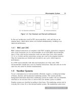
Input/Output (I/O) ports allow external digital signals to be connected to the
microcontroller. I/O ports are usually organized into groups of 8 bits and each
group is given a name. For example, the 8051 microcontroller contains four
8-bit I/O ports named P0, P1, P2, and P3. On some microcontrollers the
direction of the I/O port lines are programmable so that dierent bits of a port
can be programmed as inputs or outputs. Some microcontrollers (including the
8051 family) provide bi-directional I/O ports. Each I/O port line of such
microcontrollers can be used as inputs and outputs. Some microcontrollers
provide `open-drain' outputs where the output transistors are left ¯oating (e.g.
port P0 of the 8051 family). External pull-up resistors are normally used with
such output port lines.
3
Microcomputer Systems
1.4
8051 Family
The 8051 family is a popular, industry standard 8-bit single chip microcomputer (microcontroller) family, manufactured by various companies with
many dierent capabilities. The basic standard device, which is the ®rst
member of the family, is the 8051, which is a 40-pin microcontroller. This
basic device is now available in several con®gurations. The 80C51 is the lowpower CMOS version of the family. The 8751 contains EPROM program
memory, used mainly during development work. The 89C51 contains ¯ash
programmable and erasable memory (PEROM) where the program memory
can be reprogrammed without erasing the chip with ultraviolet light. The 8052
is an enhanced member of the family which contains more RAM and also more
timer/counters. There are many versions of the 40-pin family which contain onchip analogue-to-digital converters, pulse-width modulators, and so on. At the
lower end of the 8051 family we have the 20-pin microcontrollers which are
code compatible with the 40-pin devices. The 20-pin devices have been
manufactured for less complex applications where the I/O requirements are
not very high and where less power is required (e.g. in portable applications).
The AT89C1051 and AT89C2051 (manufactured by Atmel) are such microcontrollers, which are fully code compatible with the 8051 family and oer
reduced power and less functionality. Table 1.1 gives a list of the characteristics
of some members of the 8051 family.
Table 1.1
Some popular members of the 8051 family
Device
Program
memory
AT89C1051
1K ¯ash
AT89C2051
Data
memory
Timer/
counters
I/O pins
Pin
count
64 RAM
1
15
20
2K ¯ash
128 RAM
2
15
20
AT89C51
4K ¯ash
128 RAM
2
32
40
AT89C52
8K ¯ash
256 RAM
3
32
40
8051AH
4K ROM
128 RAM
2
32
40
87C51H
4K EPROM
128 RAM
2
32
40
8052AH
8K ROM
256 RAM
3
32
40
87C52
8K EPROM
256 RAM
3
32
40
87C54
16K EPROM
256 RAM
3
32
40
87C58
32K EPROM
256 RAM
3
32
40
4
Microcontroller Projects in C for the 8051
In this book all the projects are based upon the AT89C2051 microcontroller.
The code given will run on other members of the family, including the 40-pin
devices. The reasons for choosing the AT89C2051 are its low cost, low power
consumption, small space (20 pin), and powerful features.
In this chapter we shall be looking at the features of the 8051 family brie¯y
with more emphasis on the smaller AT89C2051. More information on these
microcontrollers can be obtained from the manufacturers' data sheets.
1.5
Architecture of the 8051 Family
The 8051 is an 8-bit, low-power, high-performance microcontroller. There are
a large number of devices in the 8051 family with similar architecture and each
member of the family is downward compatible with each other. The basic 8051
microcontroller has the following features:
.
.
.
.
.
.
.
.
4 Kbytes of program memory
256 Â 8 RAM data memory
32 programmable I/O lines
Two 16-bit timer/counters
Six interrupt sources
Programmable serial UART port
External memory interface
Standard 40-pin package
The EPROM versions of the family (e.g. 8751) are used for development and
the program memory of these devices is erased with an ultraviolet light source.
The pin con®guration of the standard 8051 microcontroller is shown in
Fig. 1.1.
The AT89C2051 is a low-end member of the 8051 family, aimed for less
complex applications. This device contains a 2 Kbyte ¯ash programmable
memory (PEROM) which can be erased and reprogrammed using a suitable
programmer. The AT89C2051 contains 128 bytes of RAM and 15 programmable I/O lines. The code developed for this device runs on a standard 8051
without any modi®cation. As shown in Fig. 1.2, the AT89C2051 is housed in a
20-pin package.
1.6
Pin Con®guration
Descriptions of the various pins are given below.
Microcomputer Systems
5
Figure 1.1.
Pin con®guration of the standard 8051
RST
This is the reset input. This input should normally be at logic 0. A reset is
accomplished by holding the RST pin high for at least two machine cycles.
Power-on reset is normally performed by connecting an external capacitor and
a resistor to this pin (see Figs 1.3 and 1.4).
P3.0
This is a bi-directional I/O pin (bit 0 of port 3) with an internal pull-up resistor.
This pin also acts as the data receive input (RXD) when the device is used as an
asynchronous UART to receive serial data.
6
Microcontroller Projects in C for the 8051
Figure 1.2.
Pin con®guration of the standard AT89C2051
P3.1
This is a bi-directional I/O pin (bit 1 of port 3) with an internal pull-up resistor.
This pin also acts as the data transmit output (TXD) on the 8051 when the
device is used as an asynchronous UART to transmit serial data.
XTAL1 and XTAL2
These pins are where an external crystal should be connected for the operation
of the internal oscillator. Normally two 33 pF capacitors are connected with
the crystal as shown in Figs 1.3 and 1.4. A machine cycle is obtained by
dividing the crystal frequency by 12. Thus, with a 12 MHz crystal, the machine
cycle is 1 ms. Most machine instructions execute in one machine cycle.
P3.2
This is a bi-directional I/O pin (bit 2 of port 3) with an internal pull-up resistor.
This pin is also the external interrupt 0 (INT0) pin.
Microcomputer Systems
7
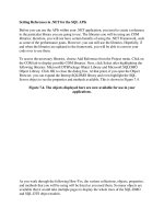
Figure 1.3.
Minimum 8051 con®guration
P3.3
This is a bi-directional I/O pin (bit 3 of port 3) with an internal pull-up resistor.
This pin is also the external interrupt 1 (INT1) pin.
P3.4
This is a bi-directional I/O pin (bit 4 of port 3) with an internal pull-up resistor.
This pin is also the counter 0 input (T0) pin.
8
Microcontroller Projects in C for the 8051
Figure 1.4.
Minimum AT89C2051 con®guration
P3.5
This is a bi-directional I/O pin (bit 5 of port 3) with an internal pull-up resistor.
This pin is also the counter 1 input (T1) pin.
GND
Ground pin.
P3.6
This is a bi-directional I/O pin. This pin is not available on the AT89C2051. It
is also the external memory write (WR) pin.
Microcomputer Systems
9
P3.7
This is a bi-directional I/O pin for bit 7 of port 3. On the standard 8051, this
pin is also the external data memory read (RD) pin.
P1.0
This is a bi-directional I/O pin for bit 0 of port 1. This pin has no internal pullup resistors on the 20-pin devices. It is also used as the positive input of the
analogue comparator (AIN0) on the 20-pin device.
P1.1
This is a bi-directional I/O pin for bit 1 of port 1. This pin has no internal pullup resistors on the 20-pin devices. It is also used as the positive input of the
analogue comparator (AIN1) on the 20-pin device.
P1.2 to P1.7
These are the remaining bi-directional I/O pins of port 1. These pins have
internal pull-up resistors.
VCC
Supply voltage.
P0.0 to P0.7
These are the eight I/O pins of port 0 of the standard 8051. These pins have no
pull-up resistors. P0.0 to P0.7 are also used to provide the low addresses (A0 to
A7) and the data during fetches from external program memory and during
accesses to external data memory.
P2.0 to P2.7
These are the eight I/O pins of port 2 of the standard 8051. These pins have
pull-up resistors. P2.0 to P2.7 are also used to provide the high address (A8 to
A15) byte during fetches from external program memory and during accesses
to external data memory.
EA/VPP
This is the external access enable pin on the standard 8051. EA should be
connected to VCC for internal program executions. This pin also receives the
programming voltage during programming.
10
Microcontroller Projects in C for the 8051
PSEN
This is the program store enable pin on the 8051 devices. This pin is activated
when the device is executing code from external memory.
ALE/PROG
This is the address latch enable pin on the standard 8051 devices. This pin is
used to latch the low byte of the address during accesses to external memory.
1.7
Timer/Counters
The 8051 and AT89C2051 contain two timer/counters known as timer/counter
0 and timer/counter 1 (larger members of the 8051 family contain more timers/
counters). These timer/counters can be operated in several dierent modes
depending upon the programming of two registers TCON and TMOD, as
shown in Tables 1.2 and 1.3. These registers should be programmed before
using any timer or counter facilities of the microcontroller.
Table 1.2
TCON timer/counter control register
Bit name
Bit position
Description
TF1
7
Timer 1 over¯ow ¯ag. Set and cleared by
hardware
TR1
6
Timer 1 run control bit. Timer 1 is turned on when
TR1 1, and stopped when TR1 0
TF0
5
Timer 0 over¯ow ¯ag. Set and cleared
by hardware
TR0
4
Timer 0 run control bit. Timer 0 is turned on
when TR0 1, and stopped when TR0 0
IE1
3
External interrupt 1 edge ¯ag. Set and cleared
by hardware
IT1
2
External interrupt 1 type. IT1 1 speci®es
interrupt on falling edge. IT1 0 speci®es
interrupt on low level
IE0
1
External interrupt 0 edge ¯ag. Set and cleared
by hardware
IT0
0
External interrupt 0 type. IT0 1 speci®es
interrupt on falling edge. IT0 0 speci®es
interrupt on low level
11
Microcomputer Systems
Table 1.3
TMOD timer/counter mode control register
TIMER 1
GATE
GATE:
C/T:
M1, M0:
TIMER 0
C/T
M1
M0
GATE
C/T
M1
M0
When TRx is set and GATE 1, TIMER/COUNTERx runs only while
the INTx pin is high. When GATE 0, TIMER/COUNTERx will run
only while TRx 1.
Timer or counter select bit. When C/T 0, operates as a timer
(from internal clock). When C/T 1, it operates as a counter
(input from Tx input).
Timer/counter mode select bits are de®ned in Table 1.4.
TCON is the timer/counter control register and this register is bit addressable.
Table 1.4 M1, M0 mode control bits
M1
M0
Operating mode
0
0
13-bit timer
0
1
16-bit timer/counter
1
0
8-bit auto-reload timer/counter
1
1
Two 8-bit timers
For example, bit 4 of TCON is the counter 0 run control bit and setting this bit
starts counter 0. TCON register is at address 88 (hex) and bits in this register
can be accessed either by making reference to the address or by using compiler
reserved names (e.g. TR0).
TMOD is the timer/counter mode control register. This register sets the
operating modes of the two timer/counters as shown in Table 1.3. There are
three operating modes, known as modes 0, 1, and 2. TMOD is not bit
addressable and should be loaded by specifying all the 8 bits. For example,
loading hexadecimal byte 01 into TMOD sets timer 0 into mode 1 which is a
16-bit timer and is turned on and o by bit TR0 of TCON. Also, timer 1 is set
into mode 0 which is a 13-bit timer and is turned on and o by bit TR1 of
TCON.
1.8
Interrupt Control
The standard 8051 and AT89C2051 provide six interrupt sources:
12
Microcontroller Projects in C for the 8051
Table 1.5
Interrupt entry locations in memory
Interrupt source
Interrupt number
Location in memory (hex)
External interrupt 0
0
0003
Timer 0
1
000B
External interrupt 1
2
0013
Timer 1
3
001B
Serial port
4
0023
Table 1.6
EA
Where:
EA:
ES:
ET1:
EX1:
ET0:
EX0:
.
.
.
.
±
±
Interrupt enable/disable bits
ES
ET1
EX1
ET0
EX0
Global interrupt enable/disable. If EA 0, no interrupt will
be accepted. If EA 1, each interrupt source is individually
enabled or disabled by setting or clearing its bit, given below.
Serial port interrupt enable bit.
Timer 1 interrupt enable bit.
External interrupt 1 enable bit.
Timer 0 interrupt enable bit.
External interrupt 0 enable bit.
Two external interrupts (INT0 and INT1)
Two timer interrupts (timer 0 and timer 1)
One serial port receive interrupt
One serial port transmit interrupt
Each interrupt is assigned a ®xed location in memory and an interrupt causes
the CPU to jump to that location, where it executes the interrupt service
routine. Table 1.5 gives the interrupt sources and the start of their service
routines in memory. Note that the serial port receive and transmit interrupts
point to the same location.
Each interrupt source can be individually enabled or disabled by setting or
clearing its interrupt enable bit. Table 1.6 gives the interrupt enable bit
patterns.
1.9
Minimum Microcontroller Con®guration
The minimum microcontroller con®gurations of the 8051- and AT89C2051based microcontroller systems are shown in Figs 1.3 and 1.4. As can be seen
Microcomputer Systems
13
from these ®gures, only the following external components are required to have
a working microcontroller:
X1
C1, C2
C3
R1
Crystal (e.g. 12 MHz)
33 pF capacitors
10 mF, 10 V electrolytic capacitor
8.2K, 0.125 W resistor
We shall be using the circuit in Fig. 1.4 in all of the projects described in this
book, except the last project which is based on a 40-pin device. The crystal
chosen for the projects is 12 MHz, which gives a basic instruction timing of
1 ms. The power supply current of the AT89C2051 is around 15 mA, but a
power supply which can deliver up to a few hundred milliamperes is
recommended so that the interface circuitry attached to the microcontroller
can be powered.
1.10 Project Development
Development of a AT89C2051 microcontroller project requires several development tools. The following is a list of the tools that are essential:
.
.
.
Suitable assembler or compiler which can generate machine code for the
AT89C2051 microcontroller. In this book we shall be developing the
projects using a C compiler.
Chip programmer suitable to program AT89C2051 devices. There are
many programmers available on the market for this purpose. For example,
PG302 by Inguana labs, Evalu8r by Equinox Technologies, and others. The
programmer should be compatible with the code generated by the
assembler or the compiler so that the code can be downloaded to the
microcontroller. Notice that there is no ultraviolet erasing process.
AT89C2051 devices contain reprogrammmable ¯ash memories which can
be erased and reprogrammed by electrical signals.
A minimum AT89C2051 microcontroller hardware. Many manufacturers
oer development systems, consisting of a basic microcontroller, LED
lights, switches, buzzers etc. Some development systems include both
language compilers and hardware and such systems can be very useful
during project development.
Although the microcontroller used in the projects is the 20-pin AT89C2051, the
code given will run on all members of the 8051 family provided that there is
enough program and data memories.
This
. Page Intentionally Left Blank
CHAPTER 2
PROGRAMMING MICROCONTROLLERS IN C
The C programming language is a general-purpose high-level programming
language that oers ecient and compact code and provides elements of
structured programming. Many control and monitoring-based applications
can be solved more eciently with C than with any other programming
language. C was originally available on mainframe computers, minicomputers, and personal computers (PCs). The C programming language is
now available on most microcontrollers and microprocessors.
This book is not intended for teaching the C programming language. It is
assumed that the reader is familiar with programming in C. The aim of this
chapter is to show the special features of the C language when programming
microcontrollers. In this book, the industry standard C51 optimizing C
compiler is used throughout. This compiler has been developed by Keil
Elektronik GmbH. C51 is available on both MS-DOS and Windows-based
operating systems and the compiler implements the American National
Standards Institute (ANSI) standard for the C language.
There are many other high-level language compilers available for microcontrollers, including PASCAL, BASIC, and other C compilers. Some of
these compilers are freely available as shareware products and some can be
obtained from the Internet with little cost. Also, some companies supply free
limited capability compilers, mainly for evaluation purposes. These compilers
can be used for learning the features of a speci®c product and in some cases
small projects can be developed with such compilers. Section 2.5 gives a list of
some sites where readers can ®nd more information on high-level microcontroller compilers.
The C51 compiler has been developed for the 8051 family of microcontrollers.
This is one of the most commonly used industry standard C compilers for the
8051 family, and can generate machine code for most of the 20-pin and 40-pin
8051 devices and its derivatives, including the following microcontrollers:
Intel and others 8051, 80C51, and 87C51
Atmel 89C51, 89C52, 89C55, 89S8252, and 89S53
Atmel 89C1051 and 89C2051
16
Microcontroller Projects in C for the 8051
AMD 80C321, 80C521, and 80C541
Dallas 80C320, 80C520, and 80C530
Signetics 8xC750, 8xC751, and 8xC752
Siemens 80C517 and 80C537
C51 is a professional, industry standard compiler with many features, including
a large number of built-in functions. In this chapter we shall be looking at the
features of the C51 programming language as applied to programming single
chip microcontrollers. More information on the C51 compiler is available from
Keil Elektronik GmbH (see the C51 Optimizing 8051 Compiler and Library
Reference Manual).
2.1
Data Types
The C51 compiler provides the standard C data types and in addition several
extended data types are oered to support the 8051 microcontroller family.
Table 2.1 lists the available data types (see the C51 reference manual for more
information).
Some of the data types are described below in more detail.
2.1.1
bit
These data types may be used to declare 1-bit variables.
Example:
bit my_¯ag;
/* declare my_¯ag as a bit variable */
my_¯ag 1;
/* set my_¯ag to 1 */
2.1.2
signed char/unsigned char
These data types are as in standard C language and are used to declare signed
and unsigned character variables. Each character variable is 1 byte long
(8 bits). Signed character variables range from À128 to 127; unsigned
character variables range from 0 to 255.
Example:
unsigned char var1,var2;
/* declare var1 and var2 as unsigned char */
var1 0xA4;
/* assign hexadecimal A4 to variable var1 */
var2 var1;
/* assign var1 to var2 */