12 static equilibrium and elasticity tủ tài liệu bách khoa
Bạn đang xem bản rút gọn của tài liệu. Xem và tải ngay bản đầy đủ của tài liệu tại đây (1.58 MB, 28 trang )
2.2
361
This is the Nearest One Head
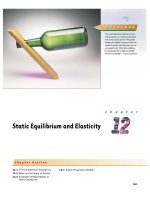
P U Z Z L E R
This one-bottle wine holder is an interesting example of a mechanical system
that seems to defy gravity. The system
(holder plus bottle) is balanced when its
center of gravity is directly over the lowest support point. What two conditions
are necessary for an object to exhibit
this kind of stability? (Charles D. Winters)
c h a p t e r
Static Equilibrium and Elasticity
Chapter Outline
12.1 The Conditions for Equilibrium
12.2 More on the Center of Gravity
12.3 Examples of Rigid Objects in
12.4 Elastic Properties of Solids
Static Equilibrium
361
362
CHAPTER 12
Static Equilibrium and Elasticity
I
n Chapters 10 and 11 we studied the dynamics of rigid objects — that is, objects
whose parts remain at a fixed separation with respect to each other when subjected to external forces. Part of this chapter addresses the conditions under
which a rigid object is in equilibrium. The term equilibrium implies either that the
object is at rest or that its center of mass moves with constant velocity. We deal
here only with the former case, in which the object is described as being in static
equilibrium. Static equilibrium represents a common situation in engineering practice, and the principles it involves are of special interest to civil engineers, architects, and mechanical engineers. If you are an engineering student you will undoubtedly take an advanced course in statics in the future.
The last section of this chapter deals with how objects deform under load conditions. Such deformations are usually elastic and do not affect the conditions for
equilibrium. An elastic object returns to its original shape when the deforming
forces are removed. Several elastic constants are defined, each corresponding to a
different type of deformation.
12.1
F
θ
THE CONDITIONS FOR EQUILIBRIUM
In Chapter 5 we stated that one necessary condition for equilibrium is that the net
force acting on an object be zero. If the object is treated as a particle, then this is
the only condition that must be satisfied for equilibrium. The situation with real
(extended) objects is more complex, however, because these objects cannot be
treated as particles. For an extended object to be in static equilibrium, a second
condition must be satisfied. This second condition involves the net torque acting
on the extended object. Note that equilibrium does not require the absence of
motion. For example, a rotating object can have constant angular velocity and still
be in equilibrium.
Consider a single force F acting on a rigid object, as shown in Figure 12.1. The
effect of the force depends on its point of application P. If r is the position vector
of this point relative to O, the torque associated with the force F about O is given
by Equation 11.7:
P
ϭr؋F
r
d
O
Figure 12.1 A single force F acts
on a rigid object at the point P.
Equivalent forces
Recall from the discussion of the vector product in Section 11.2 that the vector is
perpendicular to the plane formed by r and F. You can use the right-hand rule to
determine the direction of : Curl the fingers of your right hand in the direction
of rotation that F tends to cause about an axis through O : your thumb then points
in the direction of . Hence, in Figure 12.1 is directed toward you out of the
page.
As you can see from Figure 12.1, the tendency of F to rotate the object about
an axis through O depends on the moment arm d, as well as on the magnitude of
F. Recall that the magnitude of is Fd (see Eq. 10.19). Now suppose a rigid object
is acted on first by force F1 and later by force F2 . If the two forces have the same
magnitude, they will produce the same effect on the object only if they have the
same direction and the same line of action. In other words,
two forces F1 and F2 are equivalent if and only if F1 ϭ F2 and if and only if the
two produce the same torque about any axis.
The two forces shown in Figure 12.2 are equal in magnitude and opposite in
direction. They are not equivalent. The force directed to the right tends to rotate
363
12.1 The Conditions for Equilibrium
the object clockwise about an axis perpendicular to the diagram through O,
whereas the force directed to the left tends to rotate it counterclockwise about that
axis.
Suppose an object is pivoted about an axis through its center of mass, as
shown in Figure 12.3. Two forces of equal magnitude act in opposite directions
along parallel lines of action. A pair of forces acting in this manner form what is
called a couple. (The two forces shown in Figure 12.2 also form a couple.) Do not
make the mistake of thinking that the forces in a couple are a result of Newton’s
third law. They cannot be third-law forces because they act on the same object.
Third-law force pairs act on different objects. Because each force produces the
same torque Fd, the net torque has a magnitude of 2Fd. Clearly, the object rotates
clockwise and undergoes an angular acceleration about the axis. With respect to
rotational motion, this is a nonequilibrium situation. The net torque on the object gives rise to an angular acceleration ␣ according to the relationship ⌺ ϭ
2Fd ϭ I␣ (see Eq. 10.21).
In general, an object is in rotational equilibrium only if its angular acceleration ␣ ϭ 0. Because ⌺ ϭ I␣ for rotation about a fixed axis, our second necessary
condition for equilibrium is that the net torque about any axis must be zero.
We now have two necessary conditions for equilibrium of an object:
1. The resultant external force must equal zero.
⌺F ϭ 0
F2
F1
O
Figure 12.2 The forces F1 and
F2 are not equivalent because they
do not produce the same torque
about some axis, even though they
are equal in magnitude and opposite in direction.
(12.1)
Conditions for equilibrium
2. The resultant external torque about any axis must be zero.
⌺ ϭ 0
(12.2)
The first condition is a statement of translational equilibrium; it tells us that the
linear acceleration of the center of mass of the object must be zero when viewed
from an inertial reference frame. The second condition is a statement of rotational equilibrium and tells us that the angular acceleration about any axis must
be zero. In the special case of static equilibrium, which is the main subject of this
chapter, the object is at rest and so has no linear or angular speed (that is, vCM ϭ 0
and ϭ 0).
F
d
CM
d
Quick Quiz 12.1
(a) Is it possible for a situation to exist in which Equation 12.1 is satisfied while Equation
12.2 is not? (b) Can Equation 12.2 be satisfied while Equation 12.1 is not?
The two vector expressions given by Equations 12.1 and 12.2 are equivalent, in
general, to six scalar equations: three from the first condition for equilibrium, and
three from the second (corresponding to x, y, and z components). Hence, in a
complex system involving several forces acting in various directions, you could be
faced with solving a set of equations with many unknowns. Here, we restrict our
discussion to situations in which all the forces lie in the xy plane. (Forces whose
vector representations are in the same plane are said to be coplanar.) With this restriction, we must deal with only three scalar equations. Two of these come from
balancing the forces in the x and y directions. The third comes from the torque
equation — namely, that the net torque about any point in the xy plane must be
zero. Hence, the two conditions of equilibrium provide the equations
⌺Fx ϭ 0
⌺Fy ϭ 0
⌺ z ϭ 0
where the axis of the torque equation is arbitrary, as we now show.
(12.3)
–F
Figure 12.3 Two forces of equal
magnitude form a couple if their
lines of action are different parallel
lines. In this case, the object rotates
clockwise. The net torque about
any axis is 2Fd.
364
CHAPTER 12
Regardless of the number of forces that are acting, if an object is in translational equilibrium and if the net torque is zero about one axis, then the net torque
must also be zero about any other axis. The point can be inside or outside the
boundaries of the object. Consider an object being acted on by several forces such
that the resultant force ⌺F ϭ F1 ϩ F2 ϩ F3 ϩ иии ϭ 0. Figure 12.4 describes this
situation (for clarity, only four forces are shown). The point of application of F1
relative to O is specified by the position vector r1 . Similarly, the points of application of F2 , F3 , . . . are specified by r2 , r3 , . . . (not shown). The net torque
about an axis through O is
F1
F2
r1
O
r1 – r ′
O′
r′
F3
Static Equilibrium and Elasticity
⌺ O ϭ r1 ؋ F1 ϩ r2 ؋ F2 ϩ r3 ؋ F3 ϩ иии
F4
Figure 12.4
Construction showing that if the net torque is zero
about origin O, it is also zero about
any other origin, such as OЈ.
Now consider another arbitrary point OЈ having a position vector rЈ relative to
O. The point of application of F1 relative to OЈ is identified by the vector r1 Ϫ rЈ.
Likewise, the point of application of F2 relative to OЈ is r2 Ϫ rЈ, and so forth.
Therefore, the torque about an axis through OЈ is
⌺ O Ј ϭ (r1 Ϫ rЈ) ؋ F1 ϩ (r2 Ϫ rЈ) ؋ F2 ϩ (r3 Ϫ rЈ) ؋ F3 ϩ иии
ϭ r1 ؋ F1 ϩ r2 ؋ F2 ϩ r3 ؋ F3 ϩ иии ϪrЈ ؋ (F1 ϩ F2 ϩ F3 ϩ иии)
Because the net force is assumed to be zero (given that the object is in translational equilibrium), the last term vanishes, and we see that the torque about OЈ is
equal to the torque about O. Hence, if an object is in translational equilibrium
and the net torque is zero about one point, then the net torque must be zero
about any other point.
12.2
y
x 2,y 2
x1,y1
m2
m1
×
CM
x 3,y 3
m3
x
O
Figure 12.5 An object can be divided into many small particles
each having a specific mass and
specific coordinates. These particles can be used to locate the center of mass.
MORE ON THE CENTER OF GRAVITY
We have seen that the point at which a force is applied can be critical in determining how an object responds to that force. For example, two equal-magnitude but
oppositely directed forces result in equilibrium if they are applied at the same
point on an object. However, if the point of application of one of the forces is
moved, so that the two forces no longer act along the same line of action, then a
force couple results and the object undergoes an angular acceleration. (This is the
situation shown in Figure 12.3.)
Whenever we deal with a rigid object, one of the forces we must consider is
the force of gravity acting on it, and we must know the point of application of this
force. As we learned in Section 9.6, on every object is a special point called its center of gravity. All the various gravitational forces acting on all the various mass elements of the object are equivalent to a single gravitational force acting through
this point. Thus, to compute the torque due to the gravitational force on an object
of mass M, we need only consider the force Mg acting at the center of gravity of
the object.
How do we find this special point? As we mentioned in Section 9.6, if
we assume that g is uniform over the object, then the center of gravity of
the object coincides with its center of mass. To see that this is so, consider an
object of arbitrary shape lying in the xy plane, as illustrated in Figure 12.5.
Suppose the object is divided into a large number of particles of masses
m 1 , m 2 , m 3 , . . . having coordinates (x 1 , y 1 ), (x 2 , y 2 ), (x 3 , y 3 ), . . . . In
365
12.3 Examples of Rigid Objects in Static Equilibrium
Equation 9.28 we defined the x coordinate of the center of mass of such an object to be
x CM ϭ
⌺m i x i
m 1x 1 ϩ m 2 x 2 ϩ m 3 x 3 ϩ иии
ϭ i
m 1 ϩ m 2 ϩ m 3 ϩ иии
⌺m i
i
We use a similar equation to define the y coordinate of the center of mass, replacing each x with its y counterpart.
Let us now examine the situation from another point of view by considering the force of gravity exerted on each particle, as shown in Figure 12.6.
Each particle contributes a torque about the origin equal in magnitude to the
particle’s weight mg multiplied by its moment arm. For example, the torque due
to the force m1 g1 is m1 g 1x1 , where g 1 is the magnitude of the gravitational field
at the position of the particle of mass m 1. We wish to locate the center of gravity,
the point at which application of the single gravitational force Mg (where M ϭ
m 1 ϩ m 2 ϩ m 3 ϩ . . . is the total mass of the object) has the same effect on rotation as does the combined effect of all the individual gravitational forces m i g i .
Equating the torque resulting from Mg acting at the center of gravity to the
sum of the torques acting on the individual particles gives
(m 1g 1 ϩ m 2g 2 ϩ m 3g 3 ϩ иии)x CG ϭ m 1g 1x 1 ϩ m 2g 2x 2 ϩ m 3g 3x 3 ϩ иии
y
x1,y1
m1g
CG ×
x 2,y 2
m2g
x 3,y 3
m3g
x
O
Fg = Mg
Figure 12.6 The center of gravity
of an object is located at the center
of mass if g is constant over the
object.
This expression accounts for the fact that the gravitational field strength g can in
general vary over the object. If we assume uniform g over the object (as is usually
the case), then the g terms cancel and we obtain
x CG ϭ
m 1x 1 ϩ m 2x 2 ϩ m 3x 3 ϩ иии
m 1 ϩ m 2 ϩ m 3 ϩ иии
(12.4)
Comparing this result with Equation 9.28, we see that the center of gravity is located at the center of mass as long as the object is in a uniform gravitational field.
In several examples presented in the next section, we are concerned with homogeneous, symmetric objects. The center of gravity for any such object coincides
with its geometric center.
12.3
EXAMPLES OF RIGID OBJECTS
IN STATIC EQUILIBRIUM
The photograph of the one-bottle wine holder on the first page of this chapter
shows one example of a balanced mechanical system that seems to defy gravity. For
the system (wine holder plus bottle) to be in equilibrium, the net external force
must be zero (see Eq. 12.1) and the net external torque must be zero (see Eq.
12.2). The second condition can be satisfied only when the center of gravity of the
system is directly over the support point.
In working static equilibrium problems, it is important to recognize all the external forces acting on the object. Failure to do so results in an incorrect analysis.
When analyzing an object in equilibrium under the action of several external
forces, use the following procedure.
A large balanced rock at the Garden of the Gods in Colorado
Springs, Colorado — an example of
stable equilibrium.
366
CHAPTER 12
Static Equilibrium and Elasticity
Problem-Solving Hints
Objects in Static Equilibrium
• Draw a simple, neat diagram of the system.
• Isolate the object being analyzed. Draw a free-body diagram and then show
and label all external forces acting on the object, indicating where those
forces are applied. Do not include forces exerted by the object on its surroundings. (For systems that contain more than one object, draw a separate
free-body diagram for each one.) Try to guess the correct direction for each
force. If the direction you select leads to a negative force, do not be
alarmed; this merely means that the direction of the force is the opposite of
what you guessed.
• Establish a convenient coordinate system for the object and find the components of the forces along the two axes. Then apply the first condition for
equilibrium. Remember to keep track of the signs of all force components.
• Choose a convenient axis for calculating the net torque on the object. Remember that the choice of origin for the torque equation is arbitrary; therefore, choose an origin that simplifies your calculation as much as possible.
Note that a force that acts along a line passing through the point chosen as
the origin gives zero contribution to the torque and thus can be ignored.
The first and second conditions for equilibrium give a set of linear equations containing several unknowns, and these equations can be solved simultaneously.
EXAMPLE 12.1
The Seesaw
A uniform 40.0-N board supports a father and daughter
weighing 800 N and 350 N, respectively, as shown in Figure
12.7. If the support (called the fulcrum) is under the center of
gravity of the board and if the father is 1.00 m from the center, (a) determine the magnitude of the upward force n exerted on the board by the support.
(b) Determine where the child should sit to balance the
system.
Solution
To find this position, we must invoke the second
condition for equilibrium. Taking an axis perpendicular to
the page through the center of gravity of the board as the
axis for our torque equation (this means that the torques
Solution First note that, in addition to n, the external
forces acting on the board are the downward forces exerted
by each person and the force of gravity acting on the board.
We know that the board’s center of gravity is at its geometric
center because we were told the board is uniform. Because
the system is in static equilibrium, the upward force n must
balance all the downward forces. From ⌺ F y ϭ 0, we have,
once we define upward as the positive y direction,
n
1.00 m
x
n Ϫ 800 N Ϫ 350 N Ϫ 40.0 N ϭ 0
n ϭ 1 190 N
(The equation ⌺ F x ϭ 0 also applies, but we do not need
to consider it because no forces act horizontally on the
board.)
40.0 N
800 N
350 N
Figure 12.7
A balanced system.
367
12.3 Examples of Rigid Objects in Static Equilibrium
produced by n and the force of gravity acting on the board
about this axis are zero), we see from ⌺ ϭ 0 that
(800 N)(1.00 m) Ϫ (350 N)x ϭ 0
x ϭ 2.29 m
through the location of the father. Recall that the sign of the
torque associated with a force is positive if that force tends to
rotate the system counterclockwise, while the sign of the
torque is negative if the force tends to rotate the system
clockwise. In this case, ⌺ ϭ 0 yields
n(1.00 m) Ϫ (40.0 N)(1.00 m) Ϫ (350 N)(1.00 m ϩ x) ϭ 0
(c) Repeat part (b) for another axis.
From part (a) we know that n ϭ 1 190 N. Thus, we can solve
Solution
To illustrate that the choice of axis is arbitrary,
let us choose an axis perpendicular to the page and passing
for x to find
x ϭ 2.29 m.
This result is in agreement with
the one we obtained in part (b).
Quick Quiz 12.2
In Example 12.1, if the fulcrum did not lie under the board’s center of gravity, what other
information would you need to solve the problem?
EXAMPLE 12.2
A Weighted Hand
A person holds a 50.0-N sphere in his hand. The forearm is
horizontal, as shown in Figure 12.8a. The biceps muscle is attached 3.00 cm from the joint, and the sphere is 35.0 cm
from the joint. Find the upward force exerted by the biceps
on the forearm and the downward force exerted by the upper arm on the forearm and acting at the joint. Neglect the
weight of the forearm.
Solution We simplify the situation by modeling the forearm as a bar as shown in Figure 12.8b, where F is the upward
force exerted by the biceps and R is the downward force exerted by the upper arm at the joint. From the first condition
for equilibrium, we have, with upward as the positive y direction,
(1)
⌺ F y ϭ F Ϫ R Ϫ 50.0 N ϭ 0
From the second condition for equilibrium, we know that
the sum of the torques about any point must be zero. With
the joint O as the axis, we have
Fd Ϫ mg ᐉ ϭ 0
F
Biceps
F(3.00 cm) Ϫ (50.0 N)(35.0 cm) ϭ 0
mg = 50.0 N
d = 3.00 cm
ᐉ = 35.0 cm
F ϭ 583 N
This value for F can be substituted into Equation (1) to
give R ϭ 533 N. As this example shows, the forces at joints
and in muscles can be extremely large.
mg
O
O
d
d
ᐉ
R
mg
ᐉ
Figure 12.8
(a) The biceps muscle pulls upward with a force F
that is essentially at right angles to the forearm. (b) The mechanical
model for the system described in part (a).
EXAMPLE 12.3
Exercise
In reality, the biceps makes an angle of 15.0° with
the vertical; thus, F has both a vertical and a horizontal component. Find the magnitude of F and the components of R
when you include this fact in your analysis.
Answer
F ϭ 604 N, Rx ϭ 156 N, R y ϭ 533 N.
Standing on a Horizontal Beam
A uniform horizontal beam with a length of 8.00 m and a
weight of 200 N is attached to a wall by a pin connection. Its far
end is supported by a cable that makes an angle of 53.0° with
the horizontal (Fig. 12.9a). If a 600-N person stands 2.00 m
from the wall, find the tension in the cable, as well as the magnitude and direction of the force exerted by the wall on the beam.
368
CHAPTER 12
Static Equilibrium and Elasticity
the left end of the beam would probably move to the left as
it begins to fall. This tells us that the wall is not only holding the beam up but is also pressing outward against it.
Thus, we draw the vector R as shown in Figure 12.9b. If we
resolve T and R into horizontal and vertical components,
as shown in Figure 12.9c, and apply the first condition for
equilibrium, we obtain
(1)
(2)
⌺ F x ϭ R cos Ϫ T cos 53.0Њ ϭ 0
⌺ F y ϭ R sin ϩ T sin 53.0Њ
Ϫ 600 N Ϫ 200 N ϭ 0
53.0°
8.00 m
(a)
R
T
θ
53.0°
200 N
where we have chosen rightward and upward as our positive
directions. Because R, T, and are all unknown, we cannot
obtain a solution from these expressions alone. (The number
of simultaneous equations must equal the number of unknowns for us to be able to solve for the unknowns.)
Now let us invoke the condition for rotational equilibrium. A convenient axis to choose for our torque equation is
the one that passes through the pin connection. The feature
that makes this point so convenient is that the force R and
the horizontal component of T both have a moment arm of
zero; hence, these forces provide no torque about this point.
Recalling our counterclockwise-equals-positive convention for
the sign of the torque about an axis and noting that the moment arms of the 600-N, 200-N, and T sin 53.0° forces are
2.00 m, 4.00 m, and 8.00 m, respectively, we obtain
⌺ ϭ (T sin 53.0Њ)(8.00 m)
600 N
Ϫ (600 N )(2.00 m) Ϫ (200 N )(4.00 m) ϭ 0
(b)
T ϭ 313 N
R sin θ
T sin 53.0°
R cos θ
T cos 53.0°
200 N
2.00 m
4.00 m
600 N
Figure 12.9 (a) A uniform beam supported by a cable. (b) The
free-body diagram for the beam. (c) The free-body diagram for the
beam showing the components of R and T.
Solution
First we must identify all the external forces
acting on the beam: They are the 200-N force of gravity, the
force T exerted by the cable, the force R exerted by the
wall at the pivot, and the 600-N force that the person exerts
on the beam. These forces are all indicated in the free-body
diagram for the beam shown in Figure 12.9b. When we consider directions for forces, it sometimes is helpful if we
imagine what would happen if a force were suddenly removed. For example, if the wall were to vanish suddenly,
Thus, the torque equation with this axis gives us one of the
unknowns directly! We now substitute this value into Equations (1) and (2) and find that
R cos ϭ 188 N
R sin ϭ 550 N
We divide the second equation by the first and, recalling the
trigonometric identity sin /cos ϭ tan , we obtain
tan ϭ
550 N
ϭ 2.93
188 N
ϭ 71.1Њ
This positive value indicates that our estimate of the direction
of R was accurate.
Finally,
188 N
188 N
Rϭ
ϭ
ϭ 580 N
cos
cos 71.1Њ
If we had selected some other axis for the torque equation, the solution would have been the same. For example, if
369
12.3 Examples of Rigid Objects in Static Equilibrium
we had chosen an axis through the center of gravity of the
beam, the torque equation would involve both T and R. However, this equation, coupled with Equations (1) and (2),
could still be solved for the unknowns. Try it!
When many forces are involved in a problem of this nature, it is convenient to set up a table. For instance, for the
example just given, we could construct the following table.
Setting the sum of the terms in the last column equal to zero
represents the condition of rotational equilibrium.
EXAMPLE 12.4
Force
Component
Moment Arm
Relative to
O (m)
Torque About
O (Nиm)
T sin 53.0°
T cos 53.0°
200 N
600 N
R sin
R cos
8.00
0
4.00
2.00
0
0
(8.00)T sin 53.0°
0
Ϫ (4.00)(200)
Ϫ (2.00)(600)
0
0
The Leaning Ladder
A uniform ladder of length ᐍ and weight mg ϭ 50 N rests
against a smooth, vertical wall (Fig. 12.10a). If the coefficient
of static friction between the ladder and the ground is s ϭ
0.40, find the minimum angle min at which the ladder does
not slip.
Solution The free-body diagram showing all the external
forces acting on the ladder is illustrated in Figure 12.10b.
The reaction force R exerted by the ground on the ladder is
the vector sum of a normal force n and the force of static friction fs . The reaction force P exerted by the wall on the ladder is horizontal because the wall is frictionless. Notice how
we have included only forces that act on the ladder. For example, the forces exerted by the ladder on the ground and
on the wall are not part of the problem and thus do not appear in the free-body diagram. Applying the first condition
for equilibrium to the ladder, we have
⌺Fx ϭ f Ϫ P ϭ 0
⌺ F y ϭ n Ϫ mg ϭ 0
From the second equation we see that n ϭ mg ϭ 50 N. Furthermore, when the ladder is on the verge of slipping, the
force of friction must be a maximum, which is given by
f s,max ϭ sn ϭ 0.40(50 N) ϭ 20 N. (Recall Eq. 5.8: fs Յ s n.)
Thus, at this angle, P ϭ 20 N.
To find min , we must use the second condition for equilibrium. When we take the torques about an axis through the
origin O at the bottom of the ladder, we have
⌺ O ϭ P ᐉ sin Ϫ mg
ᐉ
cos ϭ 0
2
Because P ϭ 20 N when the ladder is about to slip, and because mg ϭ 50 N, this expression gives
tan min ϭ
mg
50 N
ϭ
ϭ 1.25
2P
40 N
min ϭ 51Њ
P
O′
ᐉ
R
n
θ
θ
φ
O
(a)
Figure 12.10
mg
f
(b)
(a) A uniform ladder at rest, leaning against a
smooth wall. The ground is rough. (b) The free-body diagram for
the ladder. Note that the forces R, mg, and P pass through a common point OЈ.
An alternative approach is to consider the intersection OЈ
of the lines of action of forces mg and P. Because the torque
about any origin must be zero, the torque about OЈ must be
zero. This requires that the line of action of R (the resultant
of n and f ) pass through OЈ. In other words, because the ladder is stationary, the three forces acting on it must all pass
through some common point. (We say that such forces are
concurrent.) With this condition, you could then obtain the
angle that R makes with the horizontal (where is greater
than ). Because this approach depends on the length of the
ladder, you would have to know the value of ᐍ to obtain a
value for min .
Exercise
For the angles labeled in Figure 12.10, show that
tan ϭ 2 tan .
370
CHAPTER 12
EXAMPLE 12.5
Static Equilibrium and Elasticity
Negotiating a Curb
(a) Estimate the magnitude of the force F a person must apply to a wheelchair’s main wheel to roll up over a sidewalk
curb (Fig. 12.11a). This main wheel, which is the one that
comes in contact with the curb, has a radius r, and the height
of the curb is h.
Solution Normally, the person’s hands supply the required force to a slightly smaller wheel that is concentric with
the main wheel. We assume that the radius of the smaller
wheel is the same as the radius of the main wheel, and so we
can use r for our radius. Let us estimate a combined weight
of mg ϭ 1 400 N for the person and the wheelchair and
choose a wheel radius of r ϭ 30 cm, as shown in Figure
12.11b. We also pick a curb height of h ϭ 10 cm. We assume
that the wheelchair and occupant are symmetric, and that
each wheel supports a weight of 700 N. We then proceed to
analyze only one of the wheels.
When the wheel is just about to be raised from the street,
the reaction force exerted by the ground on the wheel at
point Q goes to zero. Hence, at this time only three forces act
on the wheel, as shown in Figure 12.11c. However, the force
R, which is the force exerted on the wheel by the curb, acts at
point P, and so if we choose to have our axis of rotation pass
through point P, we do not need to include R in our torque
equation. From the triangle OPQ shown in Figure 12.11b, we
see that the moment arm d of the gravitational force mg acting on the wheel relative to point P is
(a)
F
O
r–h
r
h
Q
d
(b)
F
C
d ϭ !r 2 Ϫ (r Ϫ h)2 ϭ !2rh Ϫ h 2
The moment arm of F relative to point P is 2r Ϫ h. Therefore, the net torque acting on the wheel about point P is
R
O
2r – h
mgd Ϫ F(2r Ϫ h) ϭ 0
θ
mg !2rh Ϫ h 2 Ϫ F(2r Ϫ h) ϭ 0
P
mg !2rh Ϫ h 2
Fϭ
2r Ϫ h
mg
(700 N)!2(0.3 m)(0.1 m) Ϫ (0.1 m)2
ϭ 300 N
Fϭ
2(0.3 m) Ϫ 0.1 m
(c)
(Notice that we have kept only one digit as significant.) This
result indicates that the force that must be applied to each
wheel is substantial. You may want to estimate the force required to roll a wheelchair up a typical sidewalk accessibility
ramp for comparison.
(b) Determine the magnitude and direction of R.
mg
F
We use the first condition for equilibrium to determine the direction:
Dividing the second equation by the first gives
tan ϭ
mg
700 N
; ϭ 70Њ
ϭ
F
300 N
R
θ
Solution
⌺ Fx ϭ F Ϫ R cos ϭ 0
⌺ Fy ϭ R sin Ϫ mg ϭ 0
P
(d)
Figure 12.11
(a) A wheelchair and person of total weight mg being
raised over a curb by a force F. (b) Details of the wheel and curb.
(c) The free-body diagram for the wheel when it is just about to be
raised. Three forces act on the wheel at this instant: F, which is exerted
by the hand; R, which is exerted by the curb; and the gravitational
force mg. (d) The vector sum of the three external forces acting on the
wheel is zero.
12.3 Examples of Rigid Objects in Static Equilibrium
We can use the right triangle shown in Figure 12.11d to obtain R :
R ϭ !(mg)2 ϩ F 2 ϭ !(700 N)2 ϩ (300 N)2 ϭ 800 N
APPLICATION
Load: 7 200 N
B
30°
30°
D
30°
30°
E
(a)
B
FAB
D
FBC
30°
FAC
30°
⌺Fy ϭ nA ϩ nE Ϫ Fg ϭ 0
n A ϩ n E ϭ 7 200 N
Next, we calculate the torque about A, noting that the overall
length of the bridge structure is L ϭ 50 m:
⌺ ϭ Ln E Ϫ (L/2)F g ϭ 0
n E ϭ F g /2 ϭ 3 600 N
Although we could repeat the torque calculation for the right
end (point E), it should be clear from symmetry arguments
that nA ϭ 3 600 N.
Now let us balance the vertical forces acting on the pin at
point A. If we assume that strut AB is in compression, then
the force FAB that the strut exerts on the pin at point A has a
negative y component. (If the strut is actually in tension, our
calculations will result in a negative value for the magnitude
of the force, still of the correct size):
⌺ F y ϭ n A Ϫ F AB sin 30Њ ϭ 0
F AB ϭ 7 200 N
The positive result shows that our assumption of compression
was correct.
We can now find the forces acting in the strut between A
and C by considering the horizontal forces acting on the pin
at point A. Because point A is not accelerating, we can safely
assume that FAC must point toward the right (Fig. 12.12b);
this indicates that the bar between points A and C is under
tension:
⌺ F x ϭ F AC Ϫ F AB cos 30Њ ϭ 0
Now let us consider the vertical forces acting on the pin at
point C. We shall assume that strut BC is in tension. (Imagine
the subsequent motion of the pin at point C if strut BC were
to break suddenly.) On the basis of symmetry, we assert that
F BC ϭ F DC and that F AC ϭ F EC :
50 m
A
Solve this problem by noting that the three forces
acting on the wheel are concurrent (that is, that all three pass
through the point C). The three forces form the sides of the
triangle shown in Figure 12.11d.
F AC ϭ (7 200 N)cos 30Њ ϭ 6 200 N
C
nA
Exercise
Analysis of a Truss
Roofs, bridges, and other structures that must be both strong
and lightweight often are made of trusses similar to the one
shown in Figure 12.12a. Imagine that this truss structure represents part of a bridge. To approach this problem, we assume
that the structural components are connected by pin joints. We
also assume that the entire structure is free to slide horizontally because it sits on “rockers” on each end, which allow it to
move back and forth as it undergoes thermal expansion and
contraction. Assuming the mass of the bridge structure is negligible compared with the load, let us calculate the forces of tension or compression in all the structural components when it is
supporting a 7 200-N load at the center (see Problem 58).
The force notation that we use here is not of our usual format. Until now, we have used the notation FAB to mean “the
force exerted by A on B.” For this application, however, all
double-letter subscripts on F indicate only the body exerting
the force. The body on which a given force acts is not named
in the subscript. For example, in Figure 12.12, FAB is the force
exerted by strut AB on the pin at A.
First, we apply Newton’s second law to the truss as a whole
in the vertical direction. Internal forces do not enter into this
accounting. We balance the weight of the load with the normal forces exerted at the two ends by the supports on which
the bridge rests:
A
371
FDC
C
30°
FCE
FCA
⌺ F y ϭ 2 F BC sin 30Њ Ϫ 7 200 N ϭ 0
nE
30°
FEC
F BC ϭ 7 200 N
E
FED
Fg
Finally, we balance the horizontal forces on B, assuming that
strut BD is in compression:
⌺ F x ϭ F AB cos 30Њ ϩ F BC cos 30Њ Ϫ F BD ϭ 0
(b)
(7 200 N)cos 30Њ ϩ (7 200 N)cos 30Њ Ϫ F BD ϭ 0
Figure 12.12 (a) Truss structure for a bridge. (b) The forces acting on the pins at points A, C, and E. As an exercise, you should diagram the forces acting on the pin at point B.
Thus, the top bar in a bridge of this design must be very
strong.
F BD ϭ 12 000 N
372
CHAPTER 12
12.4
Static Equilibrium and Elasticity
ELASTIC PROPERTIES OF SOLIDS
In our study of mechanics thus far, we have assumed that objects remain undeformed when external forces act on them. In reality, all objects are deformable.
That is, it is possible to change the shape or the size of an object (or both) by applying external forces. As these changes take place, however, internal forces in the
object resist the deformation.
We shall discuss the deformation of solids in terms of the concepts of stress
and strain. Stress is a quantity that is proportional to the force causing a deformation; more specifically, stress is the external force acting on an object per unit
cross-sectional area. Strain is a measure of the degree of deformation. It is found
that, for sufficiently small stresses, strain is proportional to stress; the constant
of proportionality depends on the material being deformed and on the nature of
the deformation. We call this proportionality constant the elastic modulus. The
elastic modulus is therefore the ratio of the stress to the resulting strain:
Elastic modulus ϵ
stress
strain
(12.5)
In a very real sense it is a comparison of what is done to a solid object (a force is
applied) and how that object responds (it deforms to some extent).
A plastic model of an arch structure under load conditions. The wavy lines indicate regions
where the stresses are greatest. Such models are useful in designing architectural components.
373
12.4 Elastic Properties of Solids
We consider three types of deformation and define an elastic modulus for each:
1. Young’s modulus, which measures the resistance of a solid to a change in its
length
2. Shear modulus, which measures the resistance to motion of the planes of a
solid sliding past each other
3. Bulk modulus, which measures the resistance of solids or liquids to changes
in their volume
Li
Young’s Modulus: Elasticity in Length
Consider a long bar of cross-sectional area A and initial length L i that is clamped
at one end, as in Figure 12.13. When an external force is applied perpendicular to
the cross section, internal forces in the bar resist distortion (“stretching”), but the
bar attains an equilibrium in which its length Lf is greater than L i and in which
the external force is exactly balanced by internal forces. In such a situation, the
bar is said to be stressed. We define the tensile stress as the ratio of the magnitude of the external force F to the cross-sectional area A. The tensile strain in this
case is defined as the ratio of the change in length ⌬L to the original length L i .
We define Young’s modulus by a combination of these two ratios:
Yϭ
F/A
tensile stress
ϭ
tensile strain
⌬L/L i
(12.6)
Young’s modulus is typically used to characterize a rod or wire stressed under either tension or compression. Note that because strain is a dimensionless quantity,
Y has units of force per unit area. Typical values are given in Table 12.1. Experiments show (a) that for a fixed applied force, the change in length is proportional
to the original length and (b) that the force necessary to produce a given strain is
proportional to the cross-sectional area. Both of these observations are in accord
with Equation 12.6.
The elastic limit of a substance is defined as the maximum stress that can be
applied to the substance before it becomes permanently deformed. It is possible to
exceed the elastic limit of a substance by applying a sufficiently large stress, as seen
in Figure 12.14. Initially, a stress – strain curve is a straight line. As the stress increases, however, the curve is no longer straight. When the stress exceeds the elas-
∆L
A
F
Figure 12.13
A long bar
clamped at one end is stretched by
an amount ⌬L under the action of
a force F.
Young’s modulus
Stress
(MN/m2)
400
Elastic
Breaking
limit
point
300
200
100
0
Elastic
behavior
Strain
0.002 0.004 0.006 0.008 0.01
Figure 12.14
Stress-versus-strain
curve for an elastic solid.
TABLE 12.1 Typical Values for Elastic Modulus
Substance
Tungsten
Steel
Copper
Brass
Aluminum
Glass
Quartz
Water
Mercury
Young’s Modulus
(N/m2)
Shear Modulus
(N/m2)
Bulk Modulus
(N/m2)
35 ϫ 1010
20 ϫ 1010
11 ϫ 1010
9.1 ϫ 1010
7.0 ϫ 1010
6.5 – 7.8 ϫ 1010
5.6 ϫ 1010
—
—
14 ϫ 1010
8.4 ϫ 1010
4.2 ϫ 1010
3.5 ϫ 1010
2.5 ϫ 1010
2.6 – 3.2 ϫ 1010
2.6 ϫ 1010
—
—
20 ϫ 1010
6 ϫ 1010
14 ϫ 1010
6.1 ϫ 1010
7.0 ϫ 1010
5.0 – 5.5 ϫ 1010
2.7 ϫ 1010
0.21 ϫ 1010
2.8 ϫ 1010
374
CHAPTER 12
∆x
A
Static Equilibrium and Elasticity
tic limit, the object is permanently distorted and does not return to its original
shape after the stress is removed. Hence, the shape of the object is permanently
changed. As the stress is increased even further, the material ultimately breaks.
F
h
–F
Fixed face
(a)
Quick Quiz 12.3
What is Young’s modulus for the elastic solid whose stress – strain curve is depicted in Figure
12.14?
F
Quick Quiz 12.4
A material is said to be ductile if it can be stressed well beyond its elastic limit without breaking. A brittle material is one that breaks soon after the elastic limit is reached. How would
you classify the material in Figure 12.14?
fs
(b)
Figure 12.15
(a) A shear deformation in which a rectangular
block is distorted by two forces of
equal magnitude but opposite directions applied to two parallel
faces. (b) A book under shear
stress.
Shear Modulus: Elasticity of Shape
Another type of deformation occurs when an object is subjected to a force tangential to one of its faces while the opposite face is held fixed by another force (Fig.
12.15a). The stress in this case is called a shear stress. If the object is originally a
rectangular block, a shear stress results in a shape whose cross-section is a parallelogram. A book pushed sideways, as shown in Figure 12.15b, is an example of an
object subjected to a shear stress. To a first approximation (for small distortions),
no change in volume occurs with this deformation.
We define the shear stress as F/A, the ratio of the tangential force to the area
A of the face being sheared. The shear strain is defined as the ratio ⌬x/h, where
⌬x is the horizontal distance that the sheared face moves and h is the height of the
object. In terms of these quantities, the shear modulus is
Sϭ
Shear modulus
shear stress
F/A
ϭ
shear strain
⌬x/h
(12.7)
Values of the shear modulus for some representative materials are given in
Table 12.1. The unit of shear modulus is force per unit area.
Bulk Modulus: Volume Elasticity
QuickLab
Estimate the shear modulus for the
pages of your textbook. Does the
thickness of the book have any effect
on the modulus value?
Bulk modulus
Bulk modulus characterizes the response of a substance to uniform squeezing or
to a reduction in pressure when the object is placed in a partial vacuum. Suppose
that the external forces acting on an object are at right angles to all its faces, as
shown in Figure 12.16, and that they are distributed uniformly over all the faces.
As we shall see in Chapter 15, such a uniform distribution of forces occurs when
an object is immersed in a fluid. An object subject to this type of deformation undergoes a change in volume but no change in shape. The volume stress is defined as the ratio of the magnitude of the normal force F to the area A. The quantity P ϭ F/A is called the pressure. If the pressure on an object changes by an
amount ⌬P ϭ ⌬F/A, then the object will experience a volume change ⌬V. The volume strain is equal to the change in volume ⌬V divided by the initial volume Vi .
Thus, from Equation 12.5, we can characterize a volume (“bulk”) compression in
terms of the bulk modulus, which is defined as
Bϵ
volume stress
⌬F/A
⌬P
ϭϪ
ϭϪ
volume strain
⌬V/Vi
⌬V/Vi
(12.8)
375
12.4 Elastic Properties of Solids
Vi
F
Figure 12.16
Vi – ∆V
When a solid is under uniform pressure, it
undergoes a change in volume but no change in shape.
This cube is compressed on all sides by forces normal to its
six faces.
A negative sign is inserted in this defining equation so that B is a positive number.
This maneuver is necessary because an increase in pressure (positive ⌬P ) causes a
decrease in volume (negative ⌬V ) and vice versa.
Table 12.1 lists bulk moduli for some materials. If you look up such values in a
different source, you often find that the reciprocal of the bulk modulus is listed.
The reciprocal of the bulk modulus is called the compressibility of the material.
Note from Table 12.1 that both solids and liquids have a bulk modulus. However, no shear modulus and no Young’s modulus are given for liquids because a
liquid does not sustain a shearing stress or a tensile stress (it flows instead).
Prestressed Concrete
If the stress on a solid object exceeds a certain value, the object fractures. The
maximum stress that can be applied before fracture occurs depends on the nature
of the material and on the type of applied stress. For example, concrete has a tensile strength of about 2 ϫ 106 N/m2, a compressive strength of 20 ϫ 106 N/m2,
and a shear strength of 2 ϫ 106 N/m2. If the applied stress exceeds these values,
the concrete fractures. It is common practice to use large safety factors to prevent
failure in concrete structures.
Concrete is normally very brittle when it is cast in thin sections. Thus, concrete
slabs tend to sag and crack at unsupported areas, as shown in Figure 12.17a. The
slab can be strengthened by the use of steel rods to reinforce the concrete, as illustrated in Figure 12.17b. Because concrete is much stronger under compression
(squeezing) than under tension (stretching) or shear, vertical columns of concrete
can support very heavy loads, whereas horizontal beams of concrete tend to sag
and crack. However, a significant increase in shear strength is achieved if the reinforced concrete is prestressed, as shown in Figure 12.17c. As the concrete is being
poured, the steel rods are held under tension by external forces. The external
Load force
Concrete
Cracks
(a)
Figure 12.17
Steel
rod
under
tension
Steel
reinforcing
rod
(b)
(c)
(a) A concrete slab with no reinforcement tends to crack under a heavy load.
(b) The strength of the concrete is increased by using steel reinforcement rods. (c) The concrete
is further strengthened by prestressing it with steel rods under tension.
QuickLab
Support a new flat eraser (art gum or
Pink Pearl will do) on two parallel
pencils at least 3 cm apart. Press
down on the middle of the top surface just enough to make the top face
of the eraser curve a bit. Is the top
face under tension or compression?
How about the bottom? Why does a
flat slab of concrete supported at the
ends tend to crack on the bottom
face and not the top?
376
CHAPTER 12
Static Equilibrium and Elasticity
forces are released after the concrete cures; this results in a permanent tension in
the steel and hence a compressive stress on the concrete. This enables the concrete slab to support a much heavier load.
EXAMPLE 12.6
Stage Design
Recall Example 8.10, in which we analyzed a cable used to
support an actor as he swung onto the stage. The tension in
the cable was 940 N. What diameter should a 10-m-long steel
wire have if we do not want it to stretch more than 0.5 cm under these conditions?
The radius of the wire can be found from A ϭ r 2:
rϭ
! !
A
ϭ
9.4 ϫ 10Ϫ6 m2
ϭ 1.7 ϫ 10Ϫ3 m ϭ 1.7 mm
d ϭ 2r ϭ 2(1.7 mm) ϭ 3.4 mm
Solution
From the definition of Young’s modulus, we can
solve for the required cross-sectional area. Assuming that the
cross section is circular, we can determine the diameter of the
wire. From Equation 12.6, we have
Yϭ
F/A
⌬L/L i
Aϭ
FL i
(940 N)(10 m)
ϭ
ϭ 9.4 ϫ 10 Ϫ6 m2
Y ⌬L
(20 ϫ 10 10 N/m2)(0.005 m)
EXAMPLE 12.7
Squeezing a Brass Sphere
A solid brass sphere is initially surrounded by air, and the air
pressure exerted on it is 1.0 ϫ 105 N/m2 (normal atmospheric pressure). The sphere is lowered into the ocean to a
depth at which the pressure is 2.0 ϫ 107 N/m2. The volume
of the sphere in air is 0.50 m3. By how much does this volume
change once the sphere is submerged?
Solution
To provide a large margin of safety, we would probably use a
flexible cable made up of many smaller wires having a total
cross-sectional area substantially greater than our calculated
value.
From the definition of bulk modulus, we have
BϭϪ
⌬P
⌬V/Vi
⌬V ϭ Ϫ
V i ⌬P
B
Because the final pressure is so much greater than the initial
pressure, we can neglect the initial pressure and state that
⌬P ϭ Pf Ϫ Pi Ϸ Pf ϭ 2.0 ϫ 10 7 N/m2. Therefore,
⌬V ϭ Ϫ
(0.50 m3)(2.0 ϫ 10 7 N/m2)
ϭ Ϫ1.6 ϫ 10 Ϫ4 m3
6.1 ϫ 10 10 N/m2
The negative sign indicates a decrease in volume.
SUMMARY
A rigid object is in equilibrium if and only if the resultant external force acting
on it is zero and the resultant external torque on it is zero about any axis:
⌺F ϭ 0
⌺ ϭ 0
(12.1)
(12.2)
The first condition is the condition for translational equilibrium, and the second
is the condition for rotational equilibrium. These two equations allow you to analyze a great variety of problems. Make sure you can identify forces unambiguously,
create a free-body diagram, and then apply Equations 12.1 and 12.2 and solve for
the unknowns.
377
Problems
The force of gravity exerted on an object can be considered as acting at a single point called the center of gravity. The center of gravity of an object coincides
with its center of mass if the object is in a uniform gravitational field.
We can describe the elastic properties of a substance using the concepts of
stress and strain. Stress is a quantity proportional to the force producing a deformation; strain is a measure of the degree of deformation. Strain is proportional to
stress, and the constant of proportionality is the elastic modulus:
Elastic modulus ϵ
stress
strain
(12.5)
Three common types of deformation are (1) the resistance of a solid to elongation under a load, characterized by Young’s modulus Y ; (2) the resistance of a
solid to the motion of internal planes sliding past each other, characterized by the
shear modulus S ; and (3) the resistance of a solid or fluid to a volume change,
characterized by the bulk modulus B.
QUESTIONS
1. Can a body be in equilibrium if only one external force
acts on it? Explain.
2. Can a body be in equilibrium if it is in motion? Explain.
3. Locate the center of gravity for the following uniform objects: (a) sphere, (b) cube, (c) right circular cylinder.
4. The center of gravity of an object may be located outside
the object. Give a few examples for which this is the case.
5. You are given an arbitrarily shaped piece of plywood, together with a hammer, nail, and plumb bob. How could
you use these items to locate the center of gravity of the
plywood? (Hint: Use the nail to suspend the plywood.)
6. For a chair to be balanced on one leg, where must the
center of gravity of the chair be located?
7. Can an object be in equilibrium if the only torques acting
on it produce clockwise rotation?
8. A tall crate and a short crate of equal mass are placed side
by side on an incline (without touching each other). As
the incline angle is increased, which crate will topple
first? Explain.
9. When lifting a heavy object, why is it recommended to
10.
11.
12.
13.
14.
keep the back as vertical as possible, lifting from the
knees, rather than bending over and lifting from the
waist?
Give a few examples in which several forces are acting on
a system in such a way that their sum is zero but the system is not in equilibrium.
If you measure the net torque and the net force on a system to be zero, (a) could the system still be rotating with
respect to you? (b) Could it be translating with respect to
you?
A ladder is resting inclined against a wall. Would you feel
safer climbing up the ladder if you were told that the
ground is frictionless but the wall is rough or that the wall
is frictionless but the ground is rough? Justify your answer.
What kind of deformation does a cube of Jell-O exhibit
when it “jiggles”?
Ruins of ancient Greek temples often have intact vertical
columns, but few horizontal slabs of stone are still in
place. Can you think of a reason why this is so?
PROBLEMS
1, 2, 3 = straightforward, intermediate, challenging
= full solution available in the Student Solutions Manual and Study Guide
WEB = solution posted at />= Computer useful in solving problem
= Interactive Physics
= paired numerical/symbolic problems
Section 12.1 The Conditions for Equilibrium
1. A baseball player holds a 36-oz bat (weight ϭ 10.0 N)
with one hand at the point O (Fig. P12.1). The bat is in
equilibrium. The weight of the bat acts along a line
60.0 cm to the right of O. Determine the force and the
torque exerted on the bat by the player.
O
60.0 cm
mg
Figure P12.1
378
CHAPTER 12
Static Equilibrium and Elasticity
2. Write the necessary conditions of equilibrium for the
body shown in Figure P12.2. Take the origin of the
torque equation at the point O.
Section 12.2 More on the Center of Gravity
5. A 3.00-kg particle is located on the x axis at x ϭ
Ϫ 5.00 m, and a 4.00-kg particle is located on the x axis
at x ϭ 3.00 m. Find the center of gravity of this twoparticle system.
6. A circular pizza of radius R has a circular piece of radius
R/2 removed from one side, as shown in Figure P12.6.
Clearly, the center of gravity has moved from C to CЈ
along the x axis. Show that the distance from C to CЈ is
R/6. (Assume that the thickness and density of the
pizza are uniform throughout.)
Fy
ᐉ
Fx
Ry
θ
Rx
O
Fg
Figure P12.2
WEB
C
3. A uniform beam of mass m b and length ᐍ supports
blocks of masses m 1 and m 2 at two positions, as shown in
Figure P12.3. The beam rests on two points. For what
value of x will the beam be balanced at P such that the
normal force at O is zero?
Figure P12.6
7. A carpenter’s square has the shape of an L, as shown in
Figure P12.7. Locate its center of gravity.
ᐉ
2
d
m1
O
C′
m2
P
4.0 cm
CG
x
ᐉ
18.0 cm
Figure P12.3
4. A student gets his car stuck in a snow drift. Not at a loss,
having studied physics, he attaches one end of a stout
rope to the vehicle and the other end to the trunk of a
nearby tree, allowing for a very small amount of slack.
The student then exerts a force F on the center of the
rope in the direction perpendicular to the car – tree line,
as shown in Figure P12.4. If the rope is inextensible and
if the magnitude of the applied force is 500 N, what is
the force on the car? (Assume equilibrium conditions.)
12 m
4.0 cm
12.0 cm
Figure P12.7
Tree
WEB
0.50 m
F
Figure P12.4
8. Pat builds a track for his model car out of wood, as illustrated in Figure P12.8. The track is 5.00 cm wide,
1.00 m high, and 3.00 m long, and it is solid. The runway is cut so that it forms a parabola described by the
equation y ϭ (x Ϫ 3)2/9. Locate the horizontal position
of the center of gravity of this track.
9. Consider the following mass distribution: 5.00 kg at
(0, 0) m, 3.00 kg at (0, 4.00) m, and 4.00 kg at
(3.00, 0) m. Where should a fourth mass of 8.00 kg be
placed so that the center of gravity of the four-mass
arrangement will be at (0, 0)?
379
Problems
y
y = (x – 3)2/9
1.00 m
15.0°
5.00 cm
x
Figure P12.11
3.00 m
Figure P12.8
10. Figure P12.10 shows three uniform objects: a rod, a
right triangle, and a square. Their masses in kilograms
and their coordinates in meters are given. Determine
the center of gravity for the three-object system.
y(m)
6.00 kg
(9,7)
(2,7)
(–5,5)
(8,5)
5.00 kg
3.00 kg
(–2,2)
(4,1)
x(m)
13. A 15.0-m uniform ladder weighing 500 N rests against a
frictionless wall. The ladder makes a 60.0° angle with
the horizontal. (a) Find the horizontal and vertical
forces that the ground exerts on the base of the ladder
when an 800-N firefighter is 4.00 m from the bottom.
(b) If the ladder is just on the verge of slipping when
the firefighter is 9.00 m up, what is the coefficient of
static friction between the ladder and the ground?
14. A uniform ladder of length L and mass m 1 rests against a
frictionless wall. The ladder makes an angle with the
horizontal. (a) Find the horizontal and vertical forces that
the ground exerts on the base of the ladder when a firefighter of mass m 2 is a distance x from the bottom. (b) If
the ladder is just on the verge of slipping when the firefighter is a distance d from the bottom, what is the coefficient of static friction between the ladder and the ground?
15. Figure P12.15 shows a claw hammer as it is being used
to pull a nail out of a horizontal surface. If a force of
magnitude 150 N is exerted horizontally as shown, find
Figure P12.10
Section 12.3 Examples of Rigid Objects
in Static Equilibrium
11. Stephen is pushing his sister Joyce in a wheelbarrow
when it is stopped by a brick 8.00 cm high (Fig.
P12.11). The handles make an angle of 15.0° from the
horizontal. A downward force of 400 N is exerted on
the wheel, which has a radius of 20.0 cm. (a) What force
must Stephen apply along the handles to just start the
wheel over the brick? (b) What is the force (magnitude
and direction) that the brick exerts on the wheel just as
the wheel begins to lift over the brick? Assume in both
parts (a) and (b) that the brick remains fixed and does
not slide along the ground.
12. Two pans of a balance are 50.0 cm apart. The fulcrum of
the balance has been shifted 1.00 cm away from the center by a dishonest shopkeeper. By what percentage is the
true weight of the goods being marked up by the shopkeeper? (Assume that the balance has negligible mass.)
F
30.0 cm
30.0°
Single point
of contact
5.00 cm
Figure P12.15
380
16.
17.
18.
19.
CHAPTER 12
Static Equilibrium and Elasticity
(a) the force exerted by the hammer claws on the nail
and (b) the force exerted by the surface on the point of
contact with the hammer head. Assume that the force
the hammer exerts on the nail is parallel to the nail.
A uniform plank with a length of 6.00 m and a mass of
30.0 kg rests horizontally across two horizontal bars of a
scaffold. The bars are 4.50 m apart, and 1.50 m of the
plank hangs over one side of the scaffold. Draw a freebody diagram for the plank. How far can a painter with
a mass of 70.0 kg walk on the overhanging part of the
plank before it tips?
A 1 500-kg automobile has a wheel base (the distance
between the axles) of 3.00 m. The center of mass of the
automobile is on the center line at a point 1.20 m behind the front axle. Find the force exerted by the
ground on each wheel.
A vertical post with a square cross section is 10.0 m tall.
Its bottom end is encased in a base 1.50 m tall that is
precisely square but slightly loose. A force of 5.50 N
to the right acts on the top of the post. The base maintains the post in equilibrium. Find the force that the top
of the right sidewall of the base exerts on the post. Find
the force that the bottom of the left sidewall of the base
exerts on the post.
A flexible chain weighing 40.0 N hangs between two
hooks located at the same height (Fig. P12.19). At each
hook, the tangent to the chain makes an angle ϭ
42.0° with the horizontal. Find (a) the magnitude of the
force each hook exerts on the chain and (b) the tension in the chain at its midpoint. (Hint: For part (b),
make a free-body diagram for half the chain.)
0.25 m
0.75 m
LuLu’s
Boutique
Figure P12.20
Figure P12.21
θ
Figure P12.19
20. A hemispherical sign 1.00 m in diameter and of uniform mass density is supported by two strings, as shown
in Figure P12.20. What fraction of the sign’s weight is
supported by each string?
21. Sir Lost-a-Lot dons his armor and sets out from the castle on his trusty steed in his quest to improve communication between damsels and dragons (Fig. P12.21). Unfortunately, his squire lowered the draw bridge too far
and finally stopped lowering it when it was 20.0° below
the horizontal. Lost-a-Lot and his horse stop when their
combined center of mass is 1.00 m from the end of the
bridge. The bridge is 8.00 m long and has a mass of
2 000 kg. The lift cable is attached to the bridge 5.00 m
from the hinge at the castle end and to a point on the
castle wall 12.0 m above the bridge. Lost-a-Lot’s mass
combined with that of his armor and steed is 1 000 kg.
Determine (a) the tension in the cable, as well as
(b) the horizontal and (c) the vertical force components acting on the bridge at the hinge.
22. Two identical, uniform bricks of length L are placed in
a stack over the edge of a horizontal surface such that
the maximum possible overhang without falling is
achieved, as shown in Figure P12.22. Find the distance x.
L
x
Figure P12.22
381
Problems
23. A vaulter holds a 29.4-N pole in equilibrium by exerting
an upward force U with her leading hand and a downward force D with her trailing hand, as shown in Figure
P12.23. Point C is the center of gravity of the pole.
What are the magnitudes of U and D?
30. Review Problem. A 2.00-m-long cylindrical steel wire
with a cross-sectional diameter of 4.00 mm is placed
over a light frictionless pulley, with one end of the wire
connected to a 5.00-kg mass and the other end connected to a 3.00-kg mass. By how much does the wire
stretch while the masses are in motion?
31. Review Problem. A cylindrical steel wire of length L i
with a cross-sectional diameter d is placed over a light
frictionless pulley, with one end of the wire connected
to a mass m1 and the other end connected to a mass m 2 .
By how much does the wire stretch while the masses are
in motion?
U
0.750 m
2.25 m
1.50 m
A
C
B
Fg
WEB
D
Figure P12.23
Section 12.4 Elastic Properties of Solids
24. Assume that Young’s modulus for bone is 1.50 ϫ
1010 N/m2 and that a bone will fracture if more than
1.50 ϫ 108 N/m2 is exerted. (a) What is the maximum
force that can be exerted on the femur bone in the leg
if it has a minimum effective diameter of 2.50 cm?
(b) If a force of this magnitude is applied compressively, by how much does the 25.0-cm-long bone
shorten?
25. A 200-kg load is hung on a wire with a length of 4.00 m,
a cross-sectional area of 0.200 ϫ 10Ϫ4 m2, and a Young’s
modulus of 8.00 ϫ 1010 N/m2. What is its increase in
length?
26. A steel wire 1 mm in diameter can support a tension of
0.2 kN. Suppose you need a cable made of these wires
to support a tension of 20 kN. The cable’s diameter
should be of what order of magnitude?
27. A child slides across a floor in a pair of rubber-soled
shoes. The frictional force acting on each foot is 20.0 N.
The footprint area of each shoe’s sole is 14.0 cm2, and
the thickness of each sole is 5.00 mm. Find the horizontal distance by which the upper and lower surfaces of
each sole are offset. The shear modulus of the rubber is
3.00 ϫ 106 N/m2.
28. Review Problem. A 30.0-kg hammer strikes a steel
spike 2.30 cm in diameter while moving with a speed of
20.0 m/s. The hammer rebounds with a speed of
10.0 m/s after 0.110 s. What is the average strain in the
spike during the impact?
29. If the elastic limit of copper is 1.50 ϫ 108 N/m2, determine the minimum diameter a copper wire can have
under a load of 10.0 kg if its elastic limit is not to be exceeded.
32. Calculate the density of sea water at a depth of 1 000 m,
where the water pressure is about 1.00 ϫ 107 N/m 2 .
(The density of sea water is 1.030 ϫ 103 kg/m3 at the
surface.)
33. If the shear stress exceeds about 4.00 ϫ 108 N/m2, steel
ruptures. Determine the shearing force necessary (a) to
shear a steel bolt 1.00 cm in diameter and (b) to punch
a 1.00-cm-diameter hole in a steel plate 0.500 cm thick.
34. (a) Find the minimum diameter of a steel wire 18.0 m
long that elongates no more than 9.00 mm when a load
of 380 kg is hung on its lower end. (b) If the elastic
limit for this steel is 3.00 ϫ 108 N/m2, does permanent
deformation occur with this load?
35. When water freezes, it expands by about 9.00%. What
would be the pressure increase inside your automobile’s
engine block if the water in it froze? (The bulk modulus
of ice is 2.00 ϫ 109 N/m2.)
36. For safety in climbing, a mountaineer uses a 50.0-m nylon rope that is 10.0 mm in diameter. When supporting
the 90.0-kg climber on one end, the rope elongates by
1.60 m. Find Young’s modulus for the rope material.
ADDITIONAL PROBLEMS
37. A bridge with a length of 50.0 m and a mass of 8.00 ϫ
104 kg is supported on a smooth pier at each end, as illustrated in Figure P12.37. A truck of mass 3.00 ϫ 104 kg
A
B
15.0 m
50.0 m
Figure P12.37
382
CHAPTER 12
Static Equilibrium and Elasticity
is located 15.0 m from one end. What are the forces on
the bridge at the points of support?
38. A frame in the shape of the letter A is formed from two
uniform pieces of metal, each of weight 26.0 N and
length 1.00 m. They are hinged at the top and held together by a horizontal wire 1.20 m in length (Fig.
P12.38). The structure rests on a frictionless surface. If
the wire is connected at points a distance of 0.650 m
from the top of the frame, determine the tension in the
wire.
L
53°
0.65 m
0.35 m
1.20 m
Figure P12.41
Figure P12.38
39. Refer to Figure 12.17c. A lintel of prestressed reinforced concrete is 1.50 m long. The cross-sectional area
of the concrete is 50.0 cm2. The concrete encloses one
steel reinforcing rod with a cross-sectional area of
1.50 cm2. The rod joins two strong end plates. Young’s
modulus for the concrete is 30.0 ϫ 109 N/m2. After the
concrete cures and the original tension T1 in the rod is
released, the concrete will be under a compressive stress
of 8.00 ϫ 106 N/m2. (a) By what distance will the rod
compress the concrete when the original tension in the
rod is released? (b) Under what tension T2 will the rod
still be? (c) How much longer than its unstressed length
will the rod then be? (d) When the concrete was
poured, the rod should have been stretched by what extension distance from its unstressed length? (e) Find
the required original tension T1 in the rod.
40. A solid sphere of radius R and mass M is placed in a
trough, as shown in Figure P12.40. The inner surfaces
of the trough are frictionless. Determine the forces exerted by the trough on the sphere at the two contact
points.
41. A 10.0-kg monkey climbs up a 120-N uniform ladder of
length L, as shown in Figure P12.41. The upper and
lower ends of the ladder rest on frictionless surfaces.
The lower end is fastened to the wall by a horizontal
rope that can support a maximum tension of 110 N.
(a) Draw a free-body diagram for the ladder. (b) Find
the tension in the rope when the monkey is one third
the way up the ladder. (c) Find the maximum distance
d that the monkey can climb up the ladder before the
rope breaks. Express your answer as a fraction of L.
42. A hungry bear weighing 700 N walks out on a beam in
an attempt to retrieve a basket of food hanging at the
end of the beam (Fig. P12.42). The beam is uniform,
weighs 200 N, and is 6.00 m long; the basket weighs
80.0 N. (a) Draw a free-body diagram for the beam.
(b) When the bear is at x ϭ 1.00 m, find the tension in
the wire and the components of the force exerted by
the wall on the left end of the beam. (c) If the wire can
withstand a maximum tension of 900 N, what is the
maximum distance that the bear can walk before the
wire breaks?
x
60.0°
Goodies
α
β
Figure P12.40
Figure P12.42
43. Old MacDonald had a farm, and on that farm he had a
gate (Fig. P12.43). The gate is 3.00 m wide and 1.80 m
383
Problems
θ
30.0°
d
1.80 m
2L
Figure P12.45
3.00 m
Figure P12.43
high, with hinges attached to the top and bottom. The
guy wire makes an angle of 30.0° with the top of the
gate and is tightened by a turn buckle to a tension of
200 N. The mass of the gate is 40.0 kg. (a) Determine
the horizontal force exerted on the gate by the bottom
hinge. (b) Find the horizontal force exerted by the upper hinge. (c) Determine the combined vertical force
exerted by both hinges. (d) What must the tension in
the guy wire be so that the horizontal force exerted by
the upper hinge is zero?
44. A 1 200-N uniform boom is supported by a cable, as illustrated in Figure P12.44. The boom is pivoted at the
bottom, and a 2 000-N object hangs from its top. Find
the tension in the cable and the components of the reaction force exerted on the boom by the floor.
46. A crane of mass 3 000 kg supports a load of 10 000 kg as
illustrated in Figure P12.46. The crane is pivoted with a
frictionless pin at A and rests against a smooth support
at B. Find the reaction forces at A and B.
A
1.00 m
B
2.00 m
(3 000 kg)g
10 000 kg
6.00 m
Figure P12.46
25°
3
ᐉ
4
ᐉ
2 000 N
65°
Figure P12.44
WEB
45. A uniform sign of weight Fg and width 2L hangs from a
light, horizontal beam hinged at the wall and supported
by a cable (Fig. P12.45). Determine (a) the tension in
the cable and (b) the components of the reaction force
exerted by the wall on the beam in terms of Fg , d, L,
and .
47. A ladder having a uniform density and a mass m rests
against a frictionless vertical wall, making an angle 60.0°
with the horizontal. The lower end rests on a flat surface, where the coefficient of static friction is s ϭ
0.400. A window cleaner having a mass M ϭ 2m attempts to climb the ladder. What fraction of the length
L of the ladder will the worker have reached when the
ladder begins to slip?
48. A uniform ladder weighing 200 N is leaning against a
wall (see Fig. 12.10). The ladder slips when ϭ 60.0°.
Assuming that the coefficients of static friction at the
wall and the ground are the same, obtain a value for s .
49. A 10 000-N shark is supported by a cable attached to a
4.00-m rod that can pivot at its base. Calculate the tension in the tie-rope between the wall and the rod if it is
holding the system in the position shown in Figure
P12.49. Find the horizontal and vertical forces exerted
on the base of the rod. (Neglect the weight of the rod.)
384
CHAPTER 12
Static Equilibrium and Elasticity
where T is the force exerted by the Achilles tendon on
the foot and R is the force exerted by the tibia on the
foot. Find the values of T, R, and when Fg ϭ 700 N.
51. A person bends over and lifts a 200-N object as shown in
Figure P12.51a, with his back in a horizontal position (a
terrible way to lift an object). The back muscle attached
at a point two thirds the way up the spine maintains the
position of the back, and the angle between the spine
and this muscle is 12.0°. Using the mechanical model
shown in Figure P12.51b and taking the weight of the
upper body to be 350 N, find the tension in the back
muscle and the compressional force in the spine.
20.0°
10 000 N
Back muscle
60.0°
Figure P12.49
Pivot
Ry
50. When a person stands on tiptoe (a strenuous position),
the position of the foot is as shown in Figure P12.50a.
The total weight of the body Fg is supported by the
force n exerted by the floor on the toe. A mechanical
model for the situation is shown in Figure P12.50b,
T
Rx
12.0°
200 N
350 N
(a)
Achilles
tendon
Tibia
(b)
Figure P12.51
52. Two 200-N traffic lights are suspended from a single cable, as shown in Figure 12.52. Neglecting the cable’s
weight, (a) prove that if 1 ϭ 2 , then T1 ϭ T2 .
(b) Determine the three tensions T1 , T2 , and T3 if
1 ϭ 2 ϭ 8.00°.
T2
T1
(a)
θ1
θ
T3
θ2
T
15.0°
R
18.0 cm
25.0 cm
90.0°
Figure P12.52
n
(b)
Figure P12.50
53. A force acts on a rectangular cabinet weighing 400 N, as
illustrated in Figure P12.53. (a) If the cabinet slides
with constant speed when F ϭ 200 N and h ϭ 0.400 m,
385
Problems
find the coefficient of kinetic friction and the position
of the resultant normal force. (b) If F ϭ 300 N, find the
value of h for which the cabinet just begins to tip.
be suspended from the top before the beam slips.
(b) Determine the magnitude of the reaction force at
the floor and the magnitude of the force exerted by the
beam on the rope at P in terms of m, M, and s .
w = 60 cm
F
ᐉ = 100 cm
P
37.0°
h
m
M
Figure P12.53
θ
Problems 53 and 54.
54. Consider the rectangular cabinet of Problem 53, but
with a force F applied horizontally at its upper edge.
(a) What is the minimum force that must be applied for
the cabinet to start tipping? (b) What is the minimum
coefficient of static friction required to prevent the cabinet from sliding with the application of a force of this
magnitude? (c) Find the magnitude and direction of
the minimum force required to tip the cabinet if the
point of application can be chosen anywhere on it.
55. A uniform rod of weight Fg and length L is supported at
its ends by a frictionless trough, as shown in Figure
P12.55. (a) Show that the center of gravity of the rod is
directly over point O when the rod is in equilibrium.
(b) Determine the equilibrium value of the angle .
Figure P12.57
58. Figure P12.58 shows a truss that supports a downward
force of 1 000 N applied at the point B. The truss has
negligible weight. The piers at A and C are smooth.
(a) Apply the conditions of equilibrium to prove that
nA ϭ 366 N and that nC ϭ 634 N. (b) Show that, because forces act on the light truss only at the hinge
joints, each bar of the truss must exert on each hinge
pin only a force along the length of that bar — a force
of tension or compression. (c) Find the force of tension
or compression in each of the three bars.
1 000 N
B
nA
θ
0.0
1
60.0°
30.0°
A
nC
m
30.0° 45.0°
C
O
Figure P12.55
56. Review Problem. A cue stick strikes a cue ball and delivers a horizontal impulse in such a way that the ball
rolls without slipping as it starts to move. At what height
above the ball’s center (in terms of the radius of the
ball) was the blow struck?
57. A uniform beam of mass m is inclined at an angle to
the horizontal. Its upper end produces a 90° bend in a
very rough rope tied to a wall, and its lower end rests on
a rough floor (Fig. P12.57). (a) If the coefficient of static friction between the beam and the floor is s , determine an expression for the maximum mass M that can
Figure P12.58
59. A stepladder of negligible weight is constructed as
shown in Figure P12.59. A painter with a mass of
70.0 kg stands on the ladder 3.00 m from the bottom.
Assuming that the floor is frictionless, find (a) the tension in the horizontal bar connecting the two halves of
the ladder, (b) the normal forces at A and B, and
(c) the components of the reaction force at the single
hinge C that the left half of the ladder exerts on the
right half. (Hint: Treat each half of the ladder separately.)