M05 YOUN7066 13 ISM c05 kho tài liệu bách khoa
Bạn đang xem bản rút gọn của tài liệu. Xem và tải ngay bản đầy đủ của tài liệu tại đây (1.17 MB, 65 trang )
APPLYING NEWTON’S LAWS
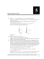
5.1.
5
IDENTIFY: a = 0 for each object. Apply ΣFy = ma y to each weight and to the pulley.
SET UP: Take + y upward. The pulley has negligible mass. Let Tr be the tension in the rope and let Tc
be the tension in the chain.
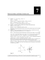
EXECUTE: (a) The free-body diagram for each weight is the same and is given in Figure 5.1a.
ΣFy = ma y gives Tr = w = 25.0 N.
(b) The free-body diagram for the pulley is given in Figure 5.1b. Tc = 2Tr = 50.0 N.
EVALUATE: The tension is the same at all points along the rope.
Figure 5.1a, b
5.2.
G
G
IDENTIFY: Apply Σ F = ma to each weight.
SET UP: Two forces act on each mass: w down and T ( = w) up.
5.3.
EXECUTE: In all cases, each string is supporting a weight w against gravity, and the tension in each string is w.
EVALUATE: The tension is the same in all three cases.
IDENTIFY: Both objects are at rest and a = 0. Apply Newton’s first law to the appropriate object. The
maximum tension Tmax is at the top of the chain and the minimum tension is at the bottom of the chain.
SET UP: Let + y be upward. For the maximum tension take the object to be the chain plus the ball. For the
minimum tension take the object to be the ball. For the tension T three-fourths of the way up from the bottom
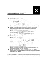
of the chain, take the chain below this point plus the ball to be the object. The free-body diagrams in each of
these three cases are sketched in Figures 5.3a, 5.3b and 5.3c. mb + c = 75.0 kg + 26.0 kg = 101.0 kg.
mb = 75.0 kg. m is the mass of three-fourths of the chain: m = 34 (26.0 kg) = 19.5 kg.
EXECUTE: (a) From Figure 5.3a, Σ Fy = 0 gives Tmax − mb + c g = 0 and
Tmax = (101.0 kg)(9.80 m/s 2 ) = 990 N. From Figure 5.3b, Σ Fy = 0 gives Tmin − mb g = 0 and
Tmin = (75.0 kg)(9.80 m/s2 ) = 735 N.
(b) From Figure 5.3c, Σ Fy = 0 gives T − (m + mb ) g = 0 and T = (19.5 kg + 75.0 kg)(9.80 m/s 2 ) = 926 N.
EVALUATE: The tension in the chain increases linearly from the bottom to the top of the chain.
© Copyright 2012 Pearson Education, Inc. All rights reserved. This material is protected under all copyright laws as they currently exist.
No portion of this material may be reproduced, in any form or by any means, without permission in writing from the publisher.
5-1
5-2
Chapter 5
Figure 5.3a–c
5.4.
IDENTIFY: For the maximum tension, the patient is just ready to slide so static friction is at its maximum
and the forces on him add to zero.
SET UP: (a) The free-body diagram for the person is given in Figure 5.4a. F is magnitude of the traction
force along the spinal column and w = mg is the person’s weight. At maximum static friction, fs = µs n.
(b) The free-body diagram for the collar where the cables are attached is given in Figure 5.4b. The tension
in each cable has been resolved into its x and y components.
Figure 5.4
EXECUTE: (a) n = w and F = fs = μs n = 0.75w = 0.75(9.80 m/s 2 )(78.5 kg) = 577 N.
F
0.75w
=
= 0.41w = (0.41)(9.80 m/s 2 )(78.5 kg) = 315 N.
2sin 65° 2sin 65°
EVALUATE: The two tensions add up to 630 N, which is more than the traction force, because the cables
do not pull directly along the spinal column.
G
G
IDENTIFY: Apply Σ F = ma to the frame.
(b) 2T sin 65° − F = 0 so T =
5.5.
5.6.
SET UP: Let w be the weight of the frame. Since the two wires make the same angle with the vertical, the
tension is the same in each wire. T = 0.75w.
EXECUTE: The vertical component of the force due to the tension in each wire must be half of the weight,
and this in turn is the tension multiplied by the cosine of the angle each wire makes with the vertical.
w 3w
=
cosθ and θ = arccos 23 = 48°.
2
4
EVALUATE: If θ = 0°, T = w/2 and T → ∞ as θ → 90°. Therefore, there must be an angle where T = 3w/ 4.
IDENTIFY: Apply Newton’s first law to the wrecking ball. Each cable exerts a force on the ball, directed
along the cable.
SET UP: The force diagram for the wrecking ball is sketched in Figure 5.6.
Figure 5.6
© Copyright 2012 Pearson Education, Inc. All rights reserved. This material is protected under all copyright laws as they currently exist.
No portion of this material may be reproduced, in any form or by any means, without permission in writing from the publisher.
Applying Newton’s Laws
5-3
EXECUTE: (a) Σ Fy = ma y
TB cos 40° − mg = 0
mg
(4090 kg)(9.80 m/s 2 )
=
= 5.23 × 10⁴ N
cos 40°
cos 40°
(b) Σ Fx = ma x
TB =
TB sin 40° − TA = 0
TA = TB sin 40° = 3.36 × 10⁴ N
5.7.
EVALUATE: If the angle 40° is replaced by 0° (cable B is vertical), then TB = mg and TA = 0.
G
G
IDENTIFY: Apply Σ F = ma to the object and to the knot where the cords are joined.
SET UP: Let + y be upward and + x be to the right.
EXECUTE: (a) TC = w, TA sin30° + TB sin 45° = TC = w, and TA cos30° − TB cos 45° = 0. Since
sin 45° = cos 45°, adding the last two equations gives TA (cos30° + sin 30°) = w, and so
TA =
cos30°
w
= 0.732w. Then, TB = TA
= 0.897 w.
1.366
cos 45°
(b) Similar to part (a), TC = w, − TA cos 60° + TB sin 45° = w, and TA sin 60° − TB cos 45° = 0.
Adding these two equations, TA =
w
sin 60°
= 2.73w, and TB = TA
= 3.35w.
(sin 60° − cos60°)
cos 45°
EVALUATE: In part (a), TA + TB > w since only the vertical components of TA and TB hold the object
5.8.
against gravity. In part (b), since TA has a downward component TB is greater than w.
IDENTIFY: Apply Newton’s first law to the car.
SET UP: Use x and y coordinates that are parallel and perpendicular to the ramp.
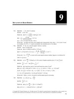
EXECUTE: (a) The free-body diagram for the car is given in Figure 5.8. The vertical weight w and the
tension T in the cable have each been replaced by their x and y components.
(b) ΣFx = 0 gives T cos31.0° − w sin 25.0° = 0 and
sin 25.0°
sin 25.0°
= (1130 kg)(9.80 m/s 2 )
= 5460 N.
cos31.0°
cos31.0°
(c) ΣFy = 0 gives n + T sin 31.0° − w cos 25.0° = 0 and
T =w
n = w cos 25.0° − T sin 31.0° = (1130 kg)(9.80 m/s 2 )cos 25.0° − (5460 N)sin 31.0° = 7220 N
EVALUATE: We could also use coordinates that are horizontal and vertical and would obtain the same
values of n and T.
Figure 5.8
© Copyright 2012 Pearson Education, Inc. All rights reserved. This material is protected under all copyright laws as they currently exist.
No portion of this material may be reproduced, in any form or by any means, without permission in writing from the publisher.
5-4
5.9.
Chapter 5
IDENTIFY: Since the velocity is constant, apply Newton’s first law to the piano. The push applied by the
man must oppose the component of gravity down the incline.
G
SET UP: The free-body diagrams for the two cases are shown in Figures 5.9a and b. F is the force applied
by the man. Use the coordinates shown in the figure.
EXECUTE: (a) Σ Fx = 0 gives F − w sin11.0° = 0 and F = (180 kg)(9.80 m/s 2 )sin11.0° = 337 N.
(b) Σ Fy = 0 gives n cos11.0° − w = 0 and n =
w
. Σ Fx = 0 gives F − n sin11.0° = 0 and
cos11.0°
w
⎛
⎞
F =⎜
⎟ sin11.0° = w tan11.0° = 343 N.
⎝ cos11.0° ⎠
Figure 5.9a, b
5.10.
IDENTIFY: Apply Newton’s first law to the hanging weight and to each knot. The tension force at each
end of a string is the same.
(a) Let the tensions in the three strings be T, T ′, and T ′′, as shown in Figure 5.10a.
Figure 5.10a
SET UP: The free-body diagram for the block is given in Figure 5.10b.
EXECUTE:
Σ Fy = 0
T′ − w = 0
T ′ = w = 60.0 N
Figure 5.10b
© Copyright 2012 Pearson Education, Inc. All rights reserved. This material is protected under all copyright laws as they currently exist.
No portion of this material may be reproduced, in any form or by any means, without permission in writing from the publisher.
Applying Newton’s Laws
5-5
SET UP: The free-body diagram for the lower knot is given in Figure 5.10c.
EXECUTE:
ΣFy = 0
T sin 45° − T ′ = 0
T′
60.0 N
T=
=
= 84.9 N
sin 45° sin 45°
Figure 5.10c
(b) Apply Σ Fx = 0 to the force diagram for the lower knot:
ΣFx = 0
F2 = T cos 45° = (84.9 N)cos 45° = 60.0 N
SET UP: The free-body diagram for the upper knot is given in Figure 5.10d.
EXECUTE:
ΣFx = 0
T cos 45° − F1 = 0
F1 = (84.9 N)cos 45°
F1 = 60.0 N
Figure 5.10d
Note that F1 = F2 .
EVALUATE: Applying Σ Fy = 0 to the upper knot gives T ′′ = T sin 45° = 60.0 N = w. If we treat the whole
system as a single object, the force diagram is given in Figure 5.10e.
ΣFx = 0 gives F2 = F1, which checks
ΣFy = 0 gives T ′′ = w, which checks
Figure 5.10e
5.11.
IDENTIFY: We apply Newton’s second law to the rocket and the astronaut in the rocket. A constant force
means we have constant acceleration, so we can use the standard kinematics equations.
SET UP: The free-body diagrams for the rocket (weight wr ) and astronaut (weight w) are given in
Figures 5.11a and 5.11b. FT is the thrust and n is the normal force the rocket exerts on the astronaut. The
speed of sound is 331 m/s. We use ΣFy = ma y and v = v0 + at .
Figure 5.11
© Copyright 2012 Pearson Education, Inc. All rights reserved. This material is protected under all copyright laws as they currently exist.
No portion of this material may be reproduced, in any form or by any means, without permission in writing from the publisher.
5-6
Chapter 5
EXECUTE:
(a) Apply Σ Fy = ma y to the rocket: FT − wr = ma. a = 4 g and wr = mg , so
F = m (5 g ) = (2.25 × 10⁶ kg) (5) (9.80 m/s 2 ) = 1.10 × 10⁸ N.
(b) Apply Σ Fy = ma y to the astronaut: n − w = ma. a = 4 g and m =
⎛ w⎞
w
, so n = w + ⎜ ⎟ (4 g ) = 5w.
g
⎝g⎠
v − v0
331 m/s
=
= 8.4 s.
a
39.2 m/s 2
EVALUATE: The 8.4 s is probably an unrealistically short time to reach the speed of sound because you
would not want your astronauts at the brink of blackout during a launch.
IDENTIFY: Apply Newton’s second law to the rocket plus its contents and to the power supply. Both the
rocket and the power supply have the same acceleration.
SET UP: The free-body diagrams for the rocket and for the power supply are given in Figures 5.12a and b.
Since the highest altitude of the rocket is 120 m, it is near to the surface of the earth and there is a
downward gravity force on each object. Let + y be upward, since that is the direction of the acceleration.
(c) v0 = 0, v = 331 m/s and a = 4 g = 39.2 m/s 2 . v = v0 + at gives t =
5.12.
The power supply has mass mps = (15.5 N)/(9.80 m/s 2 ) = 1.58 kg.
EXECUTE: (a) Σ Fy = ma y applied to the rocket gives F − mr g = mr a.
a=
F − mr g 1720 N − (125 kg)(9.80 m/s 2 )
=
= 3.96 m/s 2 .
mr
125 kg
(b) Σ Fy = ma y applied to the power supply gives n − mps g = mps a.
n = mps ( g + a ) = (1.58 kg)(9.80 m/s 2 + 3.96 m/s 2 ) = 21.7 N.
EVALUATE: The acceleration is constant while the thrust is constant and the normal force is constant
while the acceleration is constant. The altitude of 120 m is not used in the calculation.
Figure 5.12
5.13.
IDENTIFY: Use the kinematic information to find the acceleration of the capsule and the stopping time.
Use Newton’s second law to find the force F that the ground exerted on the capsule during the crash.
SET UP: Let + y be upward. 311 km/h = 86.4 m/s. The free-body diagram for the capsule is given in
Figure 5.13.
EXECUTE: y − y0 = −0.810 m, v0 y = −86.4 m/s, v y = 0. v 2y = v02y + 2a y ( y − y0 ) gives
ay =
v 2y − v02 y
2 ( y − y0 )
=
0 − (−86.4 m/s) 2
= 4610 m/s 2 = 470 g.
2 (−0.810) m
(b) Σ Fy = ma y applied to the capsule gives F − mg = ma and
F = m ( g + a ) = (210 kg) (9.80 m/s 2 + 4610 m/s 2 ) = 9.70 × 10⁵ N = 471w.
⎛ v0 y + v y ⎞
2 ( y − y0 ) 2 (−0.810 m)
(c) y − y0 = ⎜
=
= 0.0187 s
⎟ t gives t =
v0 y + v y
−86.4 m/s + 0
2
⎝
⎠
© Copyright 2012 Pearson Education, Inc. All rights reserved. This material is protected under all copyright laws as they currently exist.
No portion of this material may be reproduced, in any form or by any means, without permission in writing from the publisher.
Applying Newton’s Laws
5-7
EVALUATE: The upward force exerted by the ground is much larger than the weight of the capsule and
stops the capsule in a short amount of time. After the capsule has come to rest, the ground still exerts a
force mg on the capsule, but the large 9.70 × 10⁵ N force is exerted only for 0.0187 s.
Figure 5.13
5.14.
IDENTIFY: Apply Newton’s second law to the three sleds taken together as a composite object and to each
individual sled. All three sleds have the same horizontal acceleration a.
SET UP: The free-body diagram for the three sleds taken as a composite object is given in Figure 5.14a
and for each individual sled in Figure 5.14b–d. Let + x be to the right, in the direction of the acceleration.
mtot = 60.0 kg.
EXECUTE: (a) Σ Fx = max for the three sleds as a composite object gives P = mtot a and
a=
125 N
P
=
= 2.08 m/s 2 .
mtot 60.0 kg
(b) Σ Fx = max applied to the 10.0 kg sled gives P − TA = m10a and
TA = P − m10a = 125 N − (10.0 kg)(2.08 m/s 2 ) = 104 N. ΣFx = max applied to the 30.0 kg sled gives
TB = m30a = (30.0 kg)(2.08 m/s 2 ) = 62.4 N.
EVALUATE: If we apply Σ Fx = max to the 20.0 kg sled and calculate a from TA and TB found in part (b),
we get TA − TB = m20a. a =
TA − TB 104 N − 62.4 N
=
= 2.08 m/s 2 , which agrees with the value we
m20
20.0 kg
calculated in part (a).
Figure 5.14
5.15.
G
G
IDENTIFY: Apply Σ F = ma to the load of bricks and to the counterweight. The tension is the same at
each end of the rope. The rope pulls up with the same force (T ) on the bricks and on the counterweight.
The counterweight accelerates downward and the bricks accelerate upward; these accelerations have the
same magnitude.
(a) SET UP: The free-body diagrams for the bricks and counterweight are given in Figure 5.15.
© Copyright 2012 Pearson Education, Inc. All rights reserved. This material is protected under all copyright laws as they currently exist.
No portion of this material may be reproduced, in any form or by any means, without permission in writing from the publisher.
5-8
Chapter 5
Figure 5.15
(b) EXECUTE: Apply ΣFy = ma y to each object. The acceleration magnitude is the same for the two
G
objects. For the bricks take + y to be upward since a for the bricks is upward. For the counterweight
G
take + y to be downward since a is downward.
bricks: Σ Fy = ma y
T − m1g = m1a
counterweight: Σ Fy = ma y
m2 g − T = m2a
Add these two equations to eliminate T:
(m2 − m1) g = (m1 + m2 ) a
⎛ m − m1 ⎞
⎛ 28.0 kg − 15.0 kg ⎞
2
2
a =⎜ 2
⎟g =⎜
⎟ (9.80 m/s ) = 2.96 m/s
15
0
kg
28
0
kg
+
.
+
.
m
m
⎝
⎠
2⎠
⎝ 1
(c) T − m1g = m1a gives T = m1 (a + g ) = (15.0 kg)(2.96 m/s 2 + 9.80 m/s 2 ) = 191 N
As a check, calculate T using the other equation.
m2 g − T = m2a gives T = m2 ( g − a ) = 28.0 kg(9.80 m/s 2 − 2.96 m/s 2 ) = 191 N, which checks.
EVALUATE: The tension is 1.30 times the weight of the bricks; this causes the bricks to accelerate
upward. The tension is 0.696 times the weight of the counterweight; this causes the counterweight to
accelerate downward. If m1 = m2 , a = 0 and T = m1g = m2 g . In this special case the objects don’t move. If
5.16.
m1 = 0, a = g and T = 0; in this special case the counterweight is in free fall. Our general result is correct
in these two special cases.
IDENTIFY: In part (a) use the kinematic information and the constant acceleration equations to calculate
G
G
G
G
the acceleration of the ice. Then apply ΣF = ma. In part (b) use ΣF = ma to find the acceleration and use
this in the constant acceleration equations to find the final speed.
SET UP: Figures 5.16a and b give the free-body diagrams for the ice both with and without friction.
Let + x be directed down the ramp, so + y is perpendicular to the ramp surface. Let φ be the angle
between the ramp and the horizontal. The gravity force has been replaced by its x and y components.
EXECUTE: (a) x − x0 = 1.50 m, v0 x = 0. vx = 2.50 m/s. vx2 = v02x + 2a x ( x − x0 ) gives
vx2 − v02x (2.50 m/s) 2 − 0
a 2.08 m/s 2
.
=
= 2.08 m/s 2 . ΣFx = max gives mg sin φ = ma and sin φ = =
2( x − x0 )
2(1.50 m)
g 9.80 m/s 2
φ = 12.3°.
(b) ΣFx = max gives mg sin φ − f = ma and
ax =
a=
mg sin φ − f (8.00 kg)(9.80 m/s 2 )sin12.3° − 10.0 N
=
= 0.838 m/s 2 .
8.00 kg
m
Then x − x0 = 1.50 m, v0 x = 0. ax = 0.838 m/s 2 and vx2 = v02x + 2ax ( x − x0 ) gives
vx = 2a x ( x − x0 ) = 2(0.838 m/s 2 )(1.50 m) = 1.59 m/s
© Copyright 2012 Pearson Education, Inc. All rights reserved. This material is protected under all copyright laws as they currently exist.
No portion of this material may be reproduced, in any form or by any means, without permission in writing from the publisher.
Applying Newton’s Laws
5-9
EVALUATE: With friction present the speed at the bottom of the ramp is less.
Figure 5.16a, b
5.17.
G
G
IDENTIFY: Apply Σ F = ma to each block. Each block has the same magnitude of acceleration a.
SET UP: Assume the pulley is to the right of the 4.00 kg block. There is no friction force on the 4.00 kg
block; the only force on it is the tension in the rope. The 4.00 kg block therefore accelerates to the right and
the suspended block accelerates downward. Let + x be to the right for the 4.00 kg block, so for it a x = a ,
and let + y be downward for the suspended block, so for it a y = a.
EXECUTE: (a) The free-body diagrams for each block are given in Figures 5.17a and b.
T
10.0 N
=
= 2.50 m/s 2 .
(b) Σ Fx = ma x applied to the 4.00 kg block gives T = (4.00 kg)a and a =
4.00 kg 4.00 kg
(c) Σ Fy = ma y applied to the suspended block gives mg − T = ma and
m=
T
10.0 N
=
= 1.37 kg.
g − a 9.80 m/s 2 − 2.50 m/s 2
(d) The weight of the hanging block is mg = (1.37 kg)(9.80 m/s 2 ) = 13.4 N. This is greater than the tension
in the rope; T = 0.75mg .
EVALUATE: Since the hanging block accelerates downward, the net force on this block must be
downward and the weight of the hanging block must be greater than the tension in the rope. Note that the
blocks accelerate no matter how small m is. It is not necessary to have m > 4.00 kg, and in fact in this
problem m is less than 4.00 kg.
Figure 5.17a, b
© Copyright 2012 Pearson Education, Inc. All rights reserved. This material is protected under all copyright laws as they currently exist.
No portion of this material may be reproduced, in any form or by any means, without permission in writing from the publisher.
5-10
5.18.
Chapter 5
G
G
IDENTIFY: (a) Consider both gliders together as a single object, apply ΣF = ma , and solve for a. Use a in
a constant acceleration equation to find the required runway length.
G
G
(b) Apply ΣF = ma to the second glider and solve for the tension Tg in the towrope that connects the two
gliders.
SET UP: In part (a), set the tension Tt in the towrope between the plane and the first glider equal to its
maximum value, Tt = 12 ,000 N.
EXECUTE: (a) The free-body diagram for both gliders as a single object of mass 2m = 1400 kg is given in
Figure 5.18a. ΣFx = ma x gives Tt − 2 f = (2m)a and a =
Tt − 2 f 12,000 N − 5000 N
=
= 5.00 m/s 2 . Then
2m
1400 kg
a x = 5.00 m/s 2 , v0 x = 0 and vx = 40 m/s in vx2 = v02x + 2a x ( x − x0 ) gives ( x − x0 ) =
vx2 − v02x
= 160 m.
2a x
(b) The free-body diagram for the second glider is given in Figure 5.18b.
ΣFx = ma x gives Tg − f = ma and T = f + ma = 2500 N + (700 kg)(5.00 m/s 2 ) = 6000 N.
EVALUATE: We can verify that ΣFx = ma x is also satisfied for the first glider.
Figure 5.18
5.19.
G
G
IDENTIFY: The maximum tension in the chain is at the top of the chain. Apply ΣF = ma to the composite
object of chain and boulder. Use the constant acceleration kinematic equations to relate the acceleration to
the time.
SET UP: Let + y be upward. The free-body diagram for the composite object is given in Figure 5.19.
T = 2.50 wchain. mtot = mchain + mboulder = 1325 kg.
EXECUTE: (a) ΣFy = ma y gives T − mtot g = mtot a.
a=
T − mtot g 2.50mchain g − mtot g ⎛ 2.50mchain ⎞
=
=⎜
− 1⎟ g
mtot
mtot
⎝ mtot
⎠
⎛ 2.50[575 kg] ⎞
a=⎜
− 1⎟ (9.80 m/s 2 ) = 0.832 m/s 2
⎝ 1325 kg
⎠
(b) Assume the acceleration has its maximum value: a y = 0.832 m/s 2 , y − y0 = 125 m and v0 y = 0.
y − y0 = v0 yt + 12 a yt 2 gives t =
2( y − y0 )
2(125 m)
=
= 17.3 s
ay
0.832 m/s 2
EVALUATE: The tension in the chain is T = 1.41 × 10⁴ N and the total weight is 1.30 × 10⁴ N. The upward
force exceeds the downward force and the acceleration is upward.
© Copyright 2012 Pearson Education, Inc. All rights reserved. This material is protected under all copyright laws as they currently exist.
No portion of this material may be reproduced, in any form or by any means, without permission in writing from the publisher.
Applying Newton’s Laws
5-11
Figure 5.19
5.20.
G
G
IDENTIFY: Apply ΣF = ma to the composite object of elevator plus student (mtot = 850 kg) and also to
the student ( w = 550 N). The elevator and the student have the same acceleration.
SET UP: Let + y be upward. The free-body diagrams for the composite object and for the student are
given in Figures 5.20a and b. T is the tension in the cable and n is the scale reading, the normal force the
scale exerts on the student. The mass of the student is m = w/g = 56.1 kg.
EXECUTE: (a) ΣFy = ma y applied to the student gives n − mg = ma y .
n − mg 450 N − 550 N
=
= −1.78 m/s 2 . The elevator has a downward acceleration of 1.78 m/s 2 .
m
56.1 kg
670 N − 550 N
= 2.14 m/s 2 .
(b) a y =
56.1 kg
ay =
(c) n = 0 means a y = − g . The student should worry; the elevator is in free fall.
(d) ΣFy = ma y applied to the composite object gives T − mtot g = mtot a. T = mtot (a y + g ). In part (a),
T = (850 kg)(−1.78 m/s 2 + 9.80 m/s 2 ) = 6820 N. In part (c), a y = − g and T = 0.
EVALUATE: In part (b), T = (850 kg)(2.14 m/s 2 + 9.80 m/s 2 ) = 10 ,150 N. The weight of the composite
object is 8330 N. When the acceleration is upward the tension is greater than the weight and when the
acceleration is downward the tension is less than the weight.
Figure 5.20a, b
5.21.
IDENTIFY: While the person is in contact with the ground, he is accelerating upward and experiences two
forces: gravity downward and the upward force of the ground. Once he is in the air, only gravity acts on
him so he accelerates downward. Newton’s second law applies during the jump (and at all other times).
SET UP: Take + y to be upward. After he leaves the ground the person travels upward 60 cm and his
acceleration is g = 9.80 m/s 2 , downward. His weight is w so his mass is w/g . ΣFy = ma y and
v 2y = v02y + 2a y ( y − y0 ) apply to the jumper.
EXECUTE: (a) v y = 0 (at the maximum height), y − y0 = 0.60 m, a y = − 9.80 m/s 2 .
v 2y = v02y + 2a y ( y − y0 ) gives v0 y = −2a y ( y − y0 ) = −2 ( −9.80 m/s 2 ) (0.60 m) = 3.4 m/s.
(b) The free-body diagram for the person while he is pushing up against the ground is given in Figure 5.21.
© Copyright 2012 Pearson Education, Inc. All rights reserved. This material is protected under all copyright laws as they currently exist.
No portion of this material may be reproduced, in any form or by any means, without permission in writing from the publisher.
5-12
Chapter 5
(c) For the jump, v0 y = 0, v y = 3.4 m/s (from part (a)), and y − y0 = 0.50 m.
v 2y = v02y + 2a y ( y − y0 ) gives a y =
v 2y − v02 y
2( y − y0 )
=
(3.4 m/s) 2 − 0
= 11.6 m/s 2 . ΣFy = ma y gives n − w = ma.
2(0.50 m)
⎛
a⎞
n = w + ma = w ⎜1 + ⎟ = 2.2w.
g⎠
⎝
Figure 5.21
5.22.
EVALUATE: To accelerate the person upward during the jump, the upward force from the ground must
exceed the downward pull of gravity. The ground pushes up on him because he pushes down on the
ground.
G
dv y
G
IDENTIFY: Acceleration and velocity are related by a y =
. Apply ΣF = ma to the rocket.
dt
G
SET UP: Let + y be upward. The free-body diagram for the rocket is sketched in Figure 5.22. F is the
thrust force.
EXECUTE: (a) v y = At + Bt 2 . a y = A + 2 Bt. At t = 0, a y = 1.50 m/s 2 so A = 1.50 m/s 2 . Then
v y = 2.00 m/s at t = 1.00 s gives 2.00 m/s = (1.50 m/s 2 )(1.00 s) + B(1.00 s) 2 and B = 0.50 m/s3.
(b) At t = 4.00 s, a y = 1.50 m/s 2 + 2(0.50 m/s3 )(4.00 s) = 5.50 m/s 2 .
(c) ΣFy = ma y applied to the rocket gives T − mg = ma and
T = m(a + g ) = (2540 kg)(9.80 m/s 2 + 5.50 m/s 2 ) = 3.89 × 10⁴ N. T = 1.56 w.
(d) When a = 1.50 m/s 2 , T = (2540 kg)(9.80 m/s 2 + 1.50 m/s 2 ) = 2.87 × 10⁴ N
EVALUATE: During the time interval when v(t ) = At + Bt 2 applies the magnitude of the acceleration is
increasing, and the thrust is increasing.
Figure 5.22
© Copyright 2012 Pearson Education, Inc. All rights reserved. This material is protected under all copyright laws as they currently exist.
No portion of this material may be reproduced, in any form or by any means, without permission in writing from the publisher.
Applying Newton’s Laws
5.23.
5-13
IDENTIFY: We know the external forces on the box and want to find the distance it moves and its speed.
The force is not constant, so the acceleration will not be constant, so we cannot use the standard constantacceleration kinematics formulas. But Newton’s second law will apply.
F
SET UP: First use Newton’s second law to find the acceleration as a function of time: a x (t ) = x . Then
m
integrate the acceleration to find the velocity as a function of time, and next integrate the velocity to find
the position as a function of time.
F
(−6.00 N/s 2 )t 2
EXECUTE: Let +x be to the right. a x (t ) = x =
= −(3.00 m/s 4 )t 2 . Integrate the acceleration
m
2.00 kg
to find the velocity as a function of time: vx (t ) = −(1.00 m/s 4 )t 3 + 9.00 m/s. Next integrate the velocity to find
the position as a function of time: x(t ) = −(0.250 m/s 4 )t 4 + (9.00 m/s)t. Now use the given values of time.
(a) vx = 0 when (1.00 m/s 4 )t 3 = 9.00 m/s. This gives t = 2.08 s. At t = 2.08 s,
x = (9.00 m/s)(2.08 s) − (0.250 m/s 4 )(2.08 s) 4 = 18.72 m − 4.68 m = 14.0 m.
(b) At t = 3.00 s, vx (t ) = −(1.00 m/s 4 )(3.00 s)3 + 9.00 m/s = −18.0 m/s, so the speed is 18.0 m/s.
5.24.
EVALUATE: The box starts out moving to the right. But because the acceleration is to the left, it reverses
direction and vx is negative in part (b).
IDENTIFY: We know the position of the crate as a function of time, so we can differentiate to find its
acceleration. Then we can apply Newton’s second law to find the upward force.
SET UP: v y (t ) = dy/dt , a y (t ) = dv y /dt , and ΣFy = ma y .
EXECUTE: Let + y be upward. dy/dt = v y (t ) = 2.80 m/s + (1.83 m/s3 )t 2 and
dv y /dt = a y (t ) = (3.66 m/s3 ) t. At t = 4.00 s, a y = 14.64 m/s 2 . Newton’s second law in the y direction
gives F − mg = ma. Solving for F gives F = 49 N + (5.00 kg)(14.64 m/s 2 ) = 122 N.
5.25.
EVALUATE: The force is greater than the weight since it is accelerating the crate upwards.
IDENTIFY: At the maximum tilt angle, the patient is just ready to slide down, so static friction is at its
maximum and the forces on the patient balance.
SET UP: Take + x to be down the incline. At the maximum angle fs = µs n and ΣFx = ma x = 0.
EXECUTE: The free-body diagram for the patient is given in Figure 5.25. ΣFy = ma y gives n = mg cosθ .
ΣFx = 0 gives mg sin θ − μs n = 0. mg sin θ − μs mg cosθ = 0. tan θ = μs so θ = 50°.
Figure 5.25
EVALUATE: A larger angle of tilt would cause more blood to flow to the brain, but it would also cause the
patient to slide down the bed.
© Copyright 2012 Pearson Education, Inc. All rights reserved. This material is protected under all copyright laws as they currently exist.
No portion of this material may be reproduced, in any form or by any means, without permission in writing from the publisher.
5-14
5.26.
Chapter 5
IDENTIFY:
G
G
fs ≤ μs n and f k = μ k n. The normal force n is determined by applying ΣF = ma to the block.
Normally, μ k ≤ μs . fs is only as large as it needs to be to prevent relative motion between the two
surfaces.
SET UP: Since the table is horizontal, with only the block present n = 135 N. With the brick on the block,
n = 270 N.
EXECUTE: (a) The friction is static for P = 0 to P = 75.0 N. The friction is kinetic for P > 75.0 N.
(b) The maximum value of fs is μs n. From the graph the maximum fs is fs = 75.0 N, so
max fs 75.0 N
f
50.0 N
=
= 0.556. f k = μ k n. From the graph, f k = 50.0 N and μ k = k =
= 0.370.
n
135 N
n 135 N
(c) When the block is moving the friction is kinetic and has the constant value f k = μ k n, independent of P.
μs =
This is why the graph is horizontal for P > 75.0 N. When the block is at rest, fs = P since this prevents
relative motion. This is why the graph for P < 75.0 N has slope +1.
(d) max fs and f k would double. The values of f on the vertical axis would double but the shape of the
5.27.
graph would be unchanged.
EVALUATE: The coefficients of friction are independent of the normal force.
(a) IDENTIFY: Constant speed implies a = 0. Apply Newton’s first law to the box. The friction force is
directed opposite to the motion of the box.
G
SET UP: Consider the free-body diagram for the box, given in Figure 5.27a. Let F be the horizontal
force applied by the worker. The friction is kinetic friction since the box is sliding along the surface.
EXECUTE:
ΣFy = ma y
n − mg = 0
n = mg
so f k = μ k n = μk mg
Figure 5.27a
ΣFx = ma x
F − fk = 0
F = f k = μ k mg = (0.20)(11.2 kg)(9.80 m/s 2 ) = 22 N
(b) IDENTIFY: Now the only horizontal force on the box is the kinetic friction force. Apply Newton’s
second law to the box to calculate its acceleration. Once we have the acceleration, we can find the
distance using a constant acceleration equation. The friction force is f k = μ k mg , just as in part (a).
SET UP: The free-body diagram is sketched in Figure 5.27b.
EXECUTE:
ΣFx = ma x
− f k = ma x
− μ k mg = ma x
a x = − μ k g = −(0.20)(9.80 m/s 2 ) = −1.96 m/s 2
Figure 5.27b
© Copyright 2012 Pearson Education, Inc. All rights reserved. This material is protected under all copyright laws as they currently exist.
No portion of this material may be reproduced, in any form or by any means, without permission in writing from the publisher.
Applying Newton’s Laws
5-15
Use the constant acceleration equations to find the distance the box travels:
vx = 0, v0 x = 3.50 m/s, a x = −1.96 m/s 2 , x − x0 = ?
vx2 = v02x + 2a x ( x − x0 )
x − x0 =
vx2 − v02x 0 − (3.50 m/s) 2
=
= 3.1 m
2a x
2(−1.96 m/s 2 )
EVALUATE: The normal force is the component of force exerted by a surface perpendicular to the surface.
G
G
Its magnitude is determined by ΣF = ma. In this case n and mg are the only vertical forces and a y = 0, so
5.28.
n = mg . Also note that f k and n are proportional in magnitude but perpendicular in direction.
G
G
IDENTIFY: Apply ΣF = ma to the box.
SET UP: Since the only vertical forces are n and w, the normal force on the box equals its weight. Static
friction is as large as it needs to be to prevent relative motion between the box and the surface, up to its
maximum possible value of fsmax = μs n. If the box is sliding then the friction force is f k = μ k n.
EXECUTE: (a) If there is no applied force, no friction force is needed to keep the box at rest.
(b) fsmax = μs n = (0.40)(40.0 N) = 16.0 N. If a horizontal force of 6.0 N is applied to the box, then
fs = 6.0 N in the opposite direction.
(c) The monkey must apply a force equal to fsmax, 16.0 N.
(d) Once the box has started moving, a force equal to f k = μk n = 8.0 N is required to keep it moving at
constant velocity.
(e) f k = 8.0 N. a = (18.0 N − 8.0 N)/(40.0 N/9.80 m/s 2 ) = 2.45 m/s 2
EVALUATE: μ k < μs and less force must be applied to the box to maintain its motion than to start it
moving.
5.29.
G
G
IDENTIFY: Apply ΣF = ma to the crate. fs ≤ μs n and f k = μ k n.
SET UP: Let + y be upward and let + x be in the direction of the push. Since the floor is horizontal and
the push is horizontal, the normal force equals the weight of the crate: n = mg = 441 N. The force it takes
to start the crate moving equals max fs and the force required to keep it moving equals f k .
EXECUTE: (a) max fs = 313 N, so μs =
313 N
208 N
= 0.710. f k = 208 N, so μ k =
= 0.472.
441 N
441 N
(b) The friction is kinetic. ΣFx = ma x gives F − f k = ma and
F = f k + ma = 208 N + (45.0 kg)(1.10 m/s 2 ) = 258 N.
(c) (i) The normal force now is mg = 72.9 N. To cause it to move,
F = max fs = μs n = (0.710)(72.9 N) = 51.8 N.
(ii) F = f k + ma and a =
5.30.
F − f k 258 N − (0.472)(72.9 N)
=
= 4.97 m/s 2
m
45.0 kg
EVALUATE: The kinetic friction force is independent of the speed of the object. On the moon, the mass of
the crate is the same as on earth, but the weight and normal force are less.
IDENTIFY: Newton’s second law applies to the rocks on the hill. When they are moving, kinetic friction
acts on them, but when they are at rest, static friction acts.
SET UP: Use coordinates with axes parallel and perpendicular to the incline, with + x in the direction of
the acceleration. ΣFx = ma x and ΣFy = ma y = 0.
EXECUTE: With the rock sliding up the hill, the friction force is down the hill. The free-body diagram is
given in Figure 5.30a.
© Copyright 2012 Pearson Education, Inc. All rights reserved. This material is protected under all copyright laws as they currently exist.
No portion of this material may be reproduced, in any form or by any means, without permission in writing from the publisher.
5-16
Chapter 5
Figure 5.30
ΣFy = ma y = 0 gives n = mg cos φ and f k = μ k n = μ k mg cos φ . ΣFx = ma x gives
mg sin φ + μk mg cos φ = ma.
a = g (sin φ + μk cos φ ) = (9.80 m/s 2 )[sin 36° + (0.45)cos36°]. a = 9.33 m/s 2 , down the incline.
(b) The component of gravity down the incline is mg sin φ = 0.588mg . The maximum possible static
friction force is fs = μs n = μs mg cos φ = 0.526mg . fs can’t be as large as mg sin φ and the rock slides back
down. As the rock slides down, f k is up the incline. The free-body diagram is given in Figure 5.30b.
ΣFy = ma y = 0 gives n = mg cos φ and f k = μ k n = μ k mg cos φ . ΣFx = ma x gives
mg sin φ − μ k mg cos φ = ma, so a = g (sin φ − μ k cos φ ) = 2.19 m/s 2 , down the incline.
5.31.
EVALUATE: The acceleration down the incline in (a) is greater than that in (b) because in (a) the static
friction and gravity are both acting down the incline, whereas in (b) friction is up the incline, opposing
gravity which still acts down the incline.
G
G
IDENTIFY: Apply ΣF = ma to the composite object consisting of the two boxes and to the top box. The
friction the ramp exerts on the lower box is kinetic friction. The upper box doesn’t slip relative to the lower
box, so the friction between the two boxes is static. Since the speed is constant the acceleration is zero.
SET UP: Let + x be up the incline. The free-body diagrams for the composite object and for the upper box
2.50 m
are given in Figures 5.31a and b. The slope angle φ of the ramp is given by tan φ =
, so
4.75 m
φ = 27.76°. Since the boxes move down the ramp, the kinetic friction force exerted on the lower box by
the ramp is directed up the incline. To prevent slipping relative to the lower box the static friction force on
the upper box is directed up the incline. mtot = 32.0 kg + 48.0 kg = 80.0 kg.
EXECUTE: (a) ΣFy = ma y applied to the composite object gives ntot = mtot g cos φ and
f k = μ k mtot g cos φ . ΣFx = ma x gives f k + T − mtot g sin φ = 0 and
T = (sin φ − μk cosφ )mtot g = (sin 27.76° − [0.444]cos 27.76°)(80.0 kg)(9.80 m/s2 ) = 57.1 N.
The person must apply a force of 57.1 N, directed up the ramp.
(b) ΣFx = ma x applied to the upper box gives fs = mg sin φ = (32.0 kg)(9.80 m/s 2 )sin 27.76° = 146 N,
directed up the ramp.
EVALUATE: For each object the net force is zero.
© Copyright 2012 Pearson Education, Inc. All rights reserved. This material is protected under all copyright laws as they currently exist.
No portion of this material may be reproduced, in any form or by any means, without permission in writing from the publisher.
Applying Newton’s Laws
5-17
Figure 5.31
5.32.
IDENTIFY: For the shortest time, the acceleration is a maximum, so the toolbox is just ready to slide
relative to the bed of the truck. The box is at rest relative to the truck, but it is accelerating relative to the
ground because the truck is accelerating. Therefore Newton’s second law will be useful.
SET UP: If the truck accelerates to the right the static friction force on the box is to the right, to try to
prevent the box from sliding relative to the truck. The free-body diagram for the box is given in
Figure 5.32. The maximum acceleration of the box occurs when fs has its maximum value, so fs = μs n.
If the box doesn’t slide, its acceleration equals the acceleration of the truck. The constant-acceleration
equation vx = v0 x + axt applies.
Figure 5.32
EXECUTE: n = mg . ΣFx = ma x gives fs = ma so μs mg = ma and a = μ s g = 6.37 m/s 2 . v0 x = 0,
vx − v0 x 30.0 m/s − 0
=
= 4.71 s
ax
6.37 m/s 2
EVALUATE: If the truck has a smaller acceleration it is still true that fs = ma, but now fs < μs n.
G
G
IDENTIFY: Use ΣF = ma to find the acceleration that can be given to the car by the kinetic friction force.
Then use a constant acceleration equation.
SET UP: Take + x in the direction the car is moving.
EXECUTE: (a) The free-body diagram for the car is shown in Figure 5.33. ΣFy = ma y gives n = mg .
vx = 30.0 m/s. vx = v0 x + axt gives t =
5.33.
ΣFx = ma x gives − μ k n = ma x . − μ k mg = ma x and a x = − μ k g . Then vx = 0 and vx2 = v02x + 2a x ( x − x0 )
gives ( x − x0 ) = −
v02x
v2
(28.7 m/s) 2
= + 0x =
= 52.5 m.
2a x
2μ k g 2(0.80)(9.80 m/s 2 )
(b) v0 x = 2μ k g ( x − x0 ) = 2(0.25)(9.80 m/s 2 )52.5 m = 16.0 m/s
© Copyright 2012 Pearson Education, Inc. All rights reserved. This material is protected under all copyright laws as they currently exist.
No portion of this material may be reproduced, in any form or by any means, without permission in writing from the publisher.
5-18
Chapter 5
EVALUATE: For constant stopping distance
v02x
μk
is constant and v0x is proportional to
μk . The answer
to part (b) can be calculated as (28.7 m/s) 0.25/0.80 = 16.0 m/s.
Figure 5.33
5.34.
IDENTIFY: Constant speed means zero acceleration for each block. If the block is moving, the friction
G
G
force the tabletop exerts on it is kinetic friction. Apply ΣF = ma to each block.
SET UP: The free-body diagrams and choice of coordinates for each block are given by Figure 5.34.
m A = 4.59 kg and mB = 2.55 kg.
EXECUTE: (a) ΣFy = ma y with a y = 0 applied to block B gives mB g − T = 0 and T = 25.0 N.
ΣFx = ma x with a x = 0 applied to block A gives T − f k = 0 and f k = 25.0 N. n A = m A g = 45.0 N and
μk =
f k 25.0 N
=
= 0.556.
n A 45.0 N
(b) Now let A be block A plus the cat, so m A = 9.18 kg. n A = 90.0 N and
f k = μk n = (0.556)(90.0 N) = 50.0 N. ∑ Fx = ma x for A gives T − f k = m Aa x . ∑ Fy = ma y for block B
gives mB g − T = mB a y . a x for A equals a y for B, so adding the two equations gives
mB g − f k = (mA + mB )a y and a y =
mB g − f k
25.0 N − 50.0 N
=
= −2.13 m/s 2 . The acceleration is
m A + mB 9.18 kg + 2.55 kg
upward and block B slows down.
EVALUATE: The equation mB g − f k = (m A + mB ) a y has a simple interpretation. If both blocks are
considered together then there are two external forces: mB g that acts to move the system one way and f k
that acts oppositely. The net force of mB g − f k must accelerate a total mass of m A + mB .
Figure 5.34
5.35.
G
G
IDENTIFY: Apply ΣF = ma to each crate. The rope exerts force T to the right on crate A and force T to
the left on crate B. The target variables are the forces T and F. Constant v implies a = 0.
SET UP: The free-body diagram for A is sketched in Figure 5.35a
© Copyright 2012 Pearson Education, Inc. All rights reserved. This material is protected under all copyright laws as they currently exist.
No portion of this material may be reproduced, in any form or by any means, without permission in writing from the publisher.
Applying Newton’s Laws
5-19
EXECUTE:
ΣFy = ma y
nA − mA g = 0
nA = mA g
f kA = μ k n A = μ k m A g
Figure 5.35a
ΣFx = ma x
T − f kA = 0
T = μk m A g
SET UP: The free-body diagram for B is sketched in Figure 5.35b.
EXECUTE:
ΣFy = ma y
nB − mB g = 0
nB = mB g
f kB = μk nB = μk mB g
Figure 5.35b
ΣFx = ma x
F − T − f kB = 0
F = T + μk mB g
Use the first equation to replace T in the second:
F = μk mA g + μk mB g .
(a) F = μk ( mA + mB ) g
(b) T = μk m A g
EVALUATE: We can also consider both crates together as a single object of mass (m A + mB ). ΣFx = ma x
5.36.
for this combined object gives F = f k = μk ( mA + mB ) g , in agreement with our answer in part (a).
G
G
IDENTIFY: Apply ΣF = ma to the box. When the box is ready to slip the static friction force has its
maximum possible value, fs = μs n.
SET UP: Use coordinates parallel and perpendicular to the ramp.
EXECUTE: (a) The normal force will be wcos α and the component of the gravitational force along the
ramp is wsin α . The box begins to slip when w sin α > μs w cos α , or tan α > μs = 0.35, so slipping occurs
at α = arctan(0.35) = 19.3°.
(b) When moving, the friction force along the ramp is μk w cos α , the component of the gravitational force
along the ramp is w sin α , so the acceleration is
( w sin α − wμ k cos α )/m = g (sin α − μ k cos α ) = 0.92 m/s 2 .
(c) Since v0 x = 0, 2ax = v 2 , so v = (2ax)1/2 , or v = [(2)(0.92m/s 2 )(5 m)]1/2 = 3 m/s.
5.37.
EVALUATE: When the box starts to move, friction changes from static to kinetic and the friction force
becomes smaller.
G
G
IDENTIFY: Apply ΣF = ma to each block. The target variables are the tension T in the cord and the
acceleration a of the blocks. Then a can be used in a constant acceleration equation to find the speed of
each block. The magnitude of the acceleration is the same for both blocks.
SET UP: The system is sketched in Figure 5.37a.
© Copyright 2012 Pearson Education, Inc. All rights reserved. This material is protected under all copyright laws as they currently exist.
No portion of this material may be reproduced, in any form or by any means, without permission in writing from the publisher.
5-20
Chapter 5
For each block take a positive
coordinate direction to be the direction
of the block’s acceleration.
Figure 5.37a
block on the table: The free-body is sketched in Figure 5.37b.
EXECUTE:
ΣFy = ma y
n − mA g = 0
n = mA g
f k = μk n = μk mA g
Figure 5.37b
ΣFx = ma x
T − f k = m Aa
T − μ k m A g = m Aa
SET UP: hanging block: The free-body is sketched in Figure 5.37c.
EXECUTE:
ΣFy = ma y
mB g − T = mB a
T = mB g − mB a
Figure 5.37c
(a) Use the second equation in the first
mB g − mB a − μk m A g = m Aa
(m A + mB ) a = (mB − μk m A ) g
a=
( mB − μk m A ) g (1.30 kg − (0.45)(2.25 kg))(9.80 m/s 2 )
=
= 0.7937 m/s 2
m A + mB
2.25 kg + 1.30 kg
SET UP: Now use the constant acceleration equations to find the final speed. Note that the blocks have the
same speeds. x − x0 = 0.0300 m, a x = 0.7937 m/s 2 , v0 x = 0, vx = ?
vx2 = v02x + 2a x ( x − x0 )
EXECUTE: vx = 2a x ( x − x0 ) = 2(0.7937 m/s 2 )(0.0300 m) = 0.218 m/s = 21.8 cm/s.
(b) T = mB g − mB a = mB ( g − a ) = 1.30 kg(9.80 m/s 2 − 0.7937 m/s 2 ) = 11.7 N
Or, to check, T − μk m A g = m Aa.
T = m A (a + μk g ) = 2.25 kg(0.7937 m/s 2 + (0.45)(9.80 m/s 2 )) = 11.7 N, which checks.
EVALUATE: The force T exerted by the cord has the same value for each block. T < mB g since the
hanging block accelerates downward. Also, f k = μk m A g = 9.92 N. T > f k and the block on the table
accelerates in the direction of T.
© Copyright 2012 Pearson Education, Inc. All rights reserved. This material is protected under all copyright laws as they currently exist.
No portion of this material may be reproduced, in any form or by any means, without permission in writing from the publisher.
Applying Newton’s Laws
5.38.
5-21
G
G
IDENTIFY: Apply ΣF = ma to the box.
SET UP: Let + y be upward and + x be horizontal, in the direction of the acceleration. Constant speed
means a = 0.
EXECUTE: (a) There is no net force in the vertical direction, so n + F sin θ − w = 0, or
n = w − F sin θ = mg − F sin θ . The friction force is f k = μk n = μk (mg − F sin θ ). The net horizontal force
is F cosθ − f k = F cosθ − μk (mg − F sin θ ), and so at constant speed,
F=
(b) Using the given values, F =
5.39.
μk mg
cosθ + μk sin θ
(0.35)(90 kg)(9.80m/s 2 )
= 290 N.
(cos 25° + (0.35)sin 25°)
EVALUATE: If θ = 0°, F = μk mg .
G
G
(a) IDENTIFY: Apply ΣF = ma to the crate. Constant v implies a = 0. Crate moving says that the friction
is kinetic friction. The target variable is the magnitude of the force applied by the woman.
SET UP: The free-body diagram for the crate is sketched in Figure 5.39.
EXECUTE:
ΣFy = ma y
n − mg − F sin θ = 0
n = mg + F sin θ
f k = μk n = μk mg + μk F sin θ
Figure 5.39
ΣFx = max
F cosθ − f k = 0
F cosθ − μk mg − μk F sin θ = 0
F (cosθ − μk sin θ ) = μk mg
μk mg
cosθ − μk sin θ
(b) IDENTIFY and SET UP: “start the crate moving” means the same force diagram as in part (a), except
μs mg
.
that μk is replaced by μs . Thus F =
cosθ − μs sin θ
F=
cosθ
1
EXECUTE: F → ∞ if cosθ − μs sin θ = 0. This gives μs =
=
.
sin θ tan θ
G
EVALUATE: F has a downward component so n > mg . If θ = 0 (woman pushes horizontally), n = mg
and F = f k = μk mg .
5.40.
G
G
IDENTIFY: Apply ΣF = ma to the ball. At the terminal speed, f = mg .
SET UP: The fluid resistance is directed opposite to the velocity of the object. At half the terminal speed,
the magnitude of the frictional force is one-fourth the weight.
EXECUTE: (a) If the ball is moving up, the frictional force is down, so the magnitude of the net force is
(5/4)w and the acceleration is (5/4) g , down.
(b) While moving down, the frictional force is up, and the magnitude of the net force is (3/4)w and the
acceleration is (3/4)g , down.
EVALUATE: The frictional force is less than mg in each case and in each case the net force is downward
and the acceleration is downward.
© Copyright 2012 Pearson Education, Inc. All rights reserved. This material is protected under all copyright laws as they currently exist.
No portion of this material may be reproduced, in any form or by any means, without permission in writing from the publisher.
5-22
5.41.
Chapter 5
IDENTIFY and SET UP: Apply Eq. (5.13).
EXECUTE: (a) Solving for D in terms of vt , D =
(b) vt =
mg
vt2
=
(80 kg)(9.80 m/s 2 )
(42 m/s) 2
= 0.44 kg/m.
(45 kg)(9.80 m/s 2 )
mg
=
= 42 m/s.
D
(0.25 kg/m)
EVALUATE: “Terminal speed depends on the mass of the falling object.”
5.42.
IDENTIFY: The acceleration of the car at the top and bottom is toward the center of the circle, and
Newton’s second law applies to it.
SET UP: Two forces are acting on the car, gravity and the normal force. At point B (the top), both forces
are toward the center of the circle, so Newton’s second law gives mg + nB = ma. At point A (the bottom),
gravity is downward but the normal force is upward, so n A − mg = ma.
EXECUTE: Solving the equation at B for the acceleration gives
mg + nB (0.800 kg)(9.8 m/s 2 ) + 6.00 N
a=
=
= 17.3 m/s 2 . Solving the equation at A for the normal force
0.800 kg
m
gives n A = m( g + a) = (0.800 kg)(9.8 m/s2 + 17.3 m/s 2 ) = 21.7 N.
5.43.
EVALUATE: The normal force at the bottom is greater than at the top because it must balance the weight
in addition to accelerate the car toward the center of its track.
G
G
IDENTIFY: Apply ΣF = ma to one of the masses. The mass moves in a circular path, so has acceleration
arad =
v2
, directed toward the center of the path.
R
SET UP: In each case, R = 0.200 m. In part (a), let + x be toward the center of the circle, so ax = arad . In
part (b) let + y be toward the center of the circle, so a y = arad . + y is downward when the mass is at the
top of the circle and + y is upward when the mass is at the bottom of the circle. Since arad has its greatest
G
G
possible value, F is in the direction of arad at both positions.
EXECUTE: (a) ΣFx = max gives F = marad = m
v=
v2
. F = 75.0 N and
R
FR
(75.0 N)(0.200 m)
=
= 3.61 m/s.
m
1.15 kg
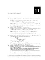
(b) The free-body diagrams for a mass at the top of the path and at the bottom of the path are given in
Figure 5.43. At the top, ΣFy = ma y gives F = marad − mg and at the bottom it gives F = mg + marad . For
a given rotation rate and hence value of arad , the value of F required is larger at the bottom of the path.
(c) F = mg + marad so
v2 F
= − g and
R m
⎛ 75.0 N
⎞
⎛F
⎞
v = R ⎜ − g ⎟ = (0.200 m) ⎜
− 9.80 m/s 2 ⎟ = 3.33 m/s
⎝m
⎠
⎝ 1.15 kg
⎠
G
EVALUATE: The maximum speed is less for the vertical circle. At the bottom of the vertical path F and
the weight are in opposite directions so F must exceed marad by an amount equal to mg. At the top of the
vertical path F and mg are in the same direction and together provide the required net force, so F must be
larger at the bottom.
© Copyright 2012 Pearson Education, Inc. All rights reserved. This material is protected under all copyright laws as they currently exist.
No portion of this material may be reproduced, in any form or by any means, without permission in writing from the publisher.
Applying Newton’s Laws
5-23
Figure 5.43
5.44.
IDENTIFY: Since the car travels in an arc of a circle, it has acceleration arad = v 2 /R, directed toward the
center of the arc. The only horizontal force on the car is the static friction force exerted by the roadway.
To calculate the minimum coefficient of friction that is required, set the static friction force equal to its
maximum value, fs = μs n. Friction is static friction because the car is not sliding in the radial direction.
SET UP: The free-body diagram for the car is given in Figure 5.44. The diagram assumes the center of the
curve is to the left of the car.
v2
v2
EXECUTE: (a) ΣFy = ma y gives n = mg . ΣFx = max gives μs n = m . μs mg = m
and
R
R
μs =
(b)
v2
(25.0 m/s) 2
=
= 0.290
gR (9.80 m/s 2 )(220 m)
v2
μs
= Rg = constant, so
v12
μs1
=
v22
μs2
. v2 = v1
μs2
μ /3
= (25.0 m/s) s1 = 14.4 m/s.
μs1
μs1
EVALUATE: A smaller coefficient of friction means a smaller maximum friction force, a smaller possible
acceleration and therefore a smaller speed.
Figure 5.44
5.45.
IDENTIFY: We can use the analysis done in Example 5.22. As in that example, we assume friction is negligible.
v2
SET UP: From Example 5.22, the banking angle β is given by tan β =
. Also, n = mg / cos β .
gR
65.0 mi/h = 29.1 m/s.
EXECUTE: (a) tan β =
(29.1 m/s) 2
and β = 21.0°. The expression for tan β does not involve
(9.80 m/s 2 )(225 m)
the mass of the vehicle, so the truck and car should travel at the same speed.
(1125 kg)(9.80 m/s 2 )
= 1.18 × 10⁴ N and ntruck = 2ncar = 2.36 × 10⁴ N, since
(b) For the car, ncar =
cos21.0°
mtruck = 2mcar .
EVALUATE: The vertical component of the normal force must equal the weight of the vehicle, so the
normal force is proportional to m.
© Copyright 2012 Pearson Education, Inc. All rights reserved. This material is protected under all copyright laws as they currently exist.
No portion of this material may be reproduced, in any form or by any means, without permission in writing from the publisher.
5-24
5.46.
Chapter 5
IDENTIFY: The acceleration of the person is arad = v 2 /R, directed horizontally to the left in the figure in
G
G
2π R
. Apply ΣF = ma to the person.
the problem. The time for one revolution is the period T =
v
SET UP: The person moves in a circle of radius R = 3.00 m + (5.00 m)sin 30.0° = 5.50 m. The free-body
G
diagram is given in Figure 5.46. F is the force applied to the seat by the rod.
mg
EXECUTE: (a) ΣFy = ma y gives F cos30.0° = mg and F =
. ΣFx = max gives
cos30.0°
F sin 30.0° = m
v2
. Combining these two equations gives
R
v = Rg tan θ = (5.50 m)(9.80 m/s 2 ) tan 30.0° = 5.58 m/s. Then the period is
2π R 2π (5.50 m)
=
= 6.19 s.
5.58 m/s
v
G
G
(b) The net force is proportional to m so in ΣF = ma the mass divides out and the angle for a given rate of
rotation is independent of the mass of the passengers.
EVALUATE: The person moves in a horizontal circle so the acceleration is horizontal. The net inward
force required for circular motion is produced by a component of the force exerted on the seat by the rod.
T=
Figure 5.46
5.47.
G
G
IDENTIFY: Apply ΣF = ma to the composite object of the person plus seat. This object moves in a
horizontal circle and has acceleration arad , directed toward the center of the circle.
SET UP: The free-body diagram for the composite object is given in Figure 5.47. Let + x be to the right,
G
in the direction of arad . Let + y be upward. The radius of the circular path is R = 7.50 m. The total mass
is (255 N + 825 N)/(9.80 m/s 2 ) = 110.2 kg. Since the rotation rate is 32.0 rev/min = 0.5333 rev/s, the
period T is
1
= 1.875 s.
0.5333 rev/s
EXECUTE: ΣFy = ma y gives TA cos 40.0° − mg = 0 and TA =
mg
255 N + 825 N
=
= 1410 N.
cos 40.0°
cos 40.0°
ΣFx = max gives TA sin 40.0° + TB = marad and
TB = m
4π 2 R
− TA sin 40.0° = (110.2 kg)
4π 2 (7.50 m)
− (1410 N)sin 40.0° = 8370 N
(1.875 s) 2
T2
The tension in the horizontal cable is 8370 N and the tension in the other cable is 1410 N.
EVALUATE: The weight of the composite object is 1080 N. The tension in cable A is larger than this since
its vertical component must equal the weight. marad = 9280 N. The tension in cable B is less than this
because part of the required inward force comes from a component of the tension in cable A.
© Copyright 2012 Pearson Education, Inc. All rights reserved. This material is protected under all copyright laws as they currently exist.
No portion of this material may be reproduced, in any form or by any means, without permission in writing from the publisher.
Applying Newton’s Laws
5-25
Figure 5.47
5.48.
G
G
IDENTIFY: Apply ΣF = ma to the button. The button moves in a circle, so it has acceleration arad .
SET UP: The situation is equivalent to that of Example 5.21.
2
v2
2π R
EXECUTE: (a) μs =
. Expressing v in terms of the period T, v =
so μs = 4π2 R . A platform
T
Rg
T g
speed of 40.0 rev/min corresponds to a period of 1.50 s, so μs =
4π 2 (0.150 m)
= 0.269.
(1.50 s)2 (9.80 m/s 2 )
(b) For the same coefficient of static friction, the maximum radius is proportional to the square of the
period (longer periods mean slower speeds, so the button may be moved farther out) and so is inversely
proportional to the square of the speed. Thus, at the higher speed, the maximum radius is
2
⎛ 40.0 ⎞
(0.150 m) ⎜
⎟ = 0.067 m.
⎝ 60.0 ⎠
4π 2 R
. The maximum radial acceleration that friction can give is μs mg. At the faster
T2
rotation rate T is smaller so R must be smaller to keep arad the same.
EVALUATE: arad =
5.49.
IDENTIFY: The acceleration due to circular motion is arad =
4π 2 R
.
T2
SET UP: R = 400 m. 1/T is the number of revolutions per second.
EXECUTE: (a) Setting arad = g and solving for the period T gives
T = 2π
400 m
R
= 2π
= 40.1 s,
g
9.80 m/s 2
so the number of revolutions per minute is (60 s/min)/(40.1 s) = 1.5 rev/min.
(b) The lower acceleration corresponds to a longer period, and hence a lower rotation rate, by a factor of
the square root of the ratio of the accelerations, T ′ = (1.5 rev/min) × 3.70 / 9.8 = 0.92 rev/min.
EVALUATE: In part (a) the tangential speed of a point at the rim is given by arad =
v2
, so
R
v = Rarad = Rg = 62.6 m/s; the space station is rotating rapidly.
5.50.
IDENTIFY: T =
2π R
. The apparent weight of a person is the normal force exerted on him by the seat he
v
is sitting on. His acceleration is arad = v 2 /R, directed toward the center of the circle.
SET UP: The period is T = 60.0 s. The passenger has mass m = w/g = 90.0 kg.
EXECUTE: (a) v =
v 2 (5.24 m/s) 2
2π R 2π (50.0 m)
=
= 0.549 m/s 2 .
=
= 5.24 m/s. Note that arad =
50.0 m
R
T
60.0 s
© Copyright 2012 Pearson Education, Inc. All rights reserved. This material is protected under all copyright laws as they currently exist.
No portion of this material may be reproduced, in any form or by any means, without permission in writing from the publisher.