Automating manufacturing systems with PLCs by hugh jack
Bạn đang xem bản rút gọn của tài liệu. Xem và tải ngay bản đầy đủ của tài liệu tại đây (7.16 MB, 846 trang )
FS = first scan
page 0
T1 = ST2 ⋅ A
A
ST1
T1
B
T3 = ST3 ⋅ ( C ⋅ B )
T3
T4 = ST2 ⋅ ( C + B )
T4
T2
ST2
ST2
T2 = ST1 ⋅ B
ST3
C*B
C+B
ST1 = ( ST1 + T1 ) ⋅ T2 + FS
ST2 = ( ST2 + T2 + T3 ) ⋅ T1 ⋅ T4
ST3 = ( ST3 + T4 ⋅ T1 ) ⋅ T3
A
T1
ST1
B
ST3
C
Automating Manufacturing Systems T2
ST2
B
with PLCs
T3
C
T4
B
(Version
4.7, April 14, 2005)
ST1
T2
ST1
T1
first scan
T1
T4
ST2
ST2
Hugh Jack
T2
T3
T3
ST3
T4
ST3
T1
page 0
Copyright (c) 1993-2005 Hugh Jack ().
This document is provided as-is with no warranty, implied or otherwise. There
have been attempts to eliminate errors from this document, but there is no doubt
that errors remain. As a result, the author does not assume any responsibility for
errors and omissions, or damages resulting from the use of the information provided.
Additional materials and updates for this work will be available at />
www.electronicbo.com
Permission is granted to copy, distribute and/or modify this document under the
terms of the GNU Free Documentation License, Version 1.2 or any later version
published by the Free Software Foundation; with no Invariant Sections, no
Front-Cover Texts, and no Back-Cover Texts. A copy of the license is included
in the section entitled "GNU Free Documentation License".
page i
1.1
2.
2.2
2.3
2.4
2.5
2.6
INTRODUCTION
2.1.1
Ladder Logic
2.1.2
Programming
2.1.3
PLC Connections
2.1.4
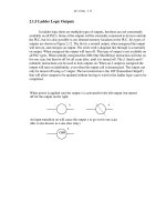
Ladder Logic Inputs
2.1.5
Ladder Logic Outputs
A CASE STUDY
SUMMARY
PRACTICE PROBLEMS
PRACTICE PROBLEM SOLUTIONS
ASSIGNMENT PROBLEMS
2.1
2.1
2.6
2.10
2.11
2.12
2.13
2.14
2.15
2.15
2.16
PLC HARDWARE . . . . . . . . . . . . . . . . . . . . . . . . . . . . . . . . . . . . 3.1
3.1
3.2
3.3
3.4
3.5
3.6
3.7
3.8
3.9
4.
1.4
PROGRAMMABLE LOGIC CONTROLLERS . . . . . . . . . . . . . 2.1
2.1
3.
TODO LIST
INTRODUCTION
INPUTS AND OUTPUTS
3.2.1
Inputs
3.2.2
Output Modules
RELAYS
A CASE STUDY
ELECTRICAL WIRING DIAGRAMS
3.5.1
JIC Wiring Symbols
SUMMARY
PRACTICE PROBLEMS
PRACTICE PROBLEM SOLUTIONS
ASSIGNMENT PROBLEMS
3.1
3.2
3.3
3.7
3.13
3.14
3.15
3.17
3.21
3.21
3.24
3.27
LOGICAL SENSORS . . . . . . . . . . . . . . . . . . . . . . . . . . . . . . . . . . 4.1
4.1
4.2
4.3
INTRODUCTION
SENSOR WIRING
4.2.1
Switches
4.2.2
Transistor Transistor Logic (TTL)
4.2.3
Sinking/Sourcing
4.2.4
Solid State Relays
PRESENCE DETECTION
4.3.1
Contact Switches
4.3.2
Reed Switches
4.3.3
Optical (Photoelectric) Sensors
4.3.4
Capacitive Sensors
4.3.5
Inductive Sensors
4.3.6
Ultrasonic
4.3.7
Hall Effect
4.1
4.1
4.2
4.3
4.3
4.10
4.11
4.11
4.11
4.12
4.19
4.23
4.25
4.25
page ii
4.4
4.5
4.6
4.7
LOGICAL ACTUATORS . . . . . . . . . . . . . . . . . . . . . . . . . . . . . . 5.1
5.1
5.2
5.3
5.4
5.5
5.6
5.7
5.8
5.9
5.10
5.11
5.12
5.13
6.
INTRODUCTION
SOLENOIDS
VALVES
CYLINDERS
HYDRAULICS
PNEUMATICS
MOTORS
COMPUTERS
OTHERS
SUMMARY
PRACTICE PROBLEMS
PRACTICE PROBLEM SOLUTIONS
ASSIGNMENT PROBLEMS
5.1
5.1
5.2
5.4
5.6
5.8
5.9
5.10
5.10
5.10
5.11
5.11
5.12
BOOLEAN LOGIC DESIGN . . . . . . . . . . . . . . . . . . . . . . . . . . . . 6.1
6.1
6.2
6.3
6.4
6.5
6.6
6.7
6.8
6.9
7.
4.26
4.26
4.27
4.30
4.36
INTRODUCTION
BOOLEAN ALGEBRA
LOGIC DESIGN
6.3.1
Boolean Algebra Techniques
COMMON LOGIC FORMS
6.4.1
Complex Gate Forms
6.4.2
Multiplexers
SIMPLE DESIGN CASES
6.5.1
Basic Logic Functions
6.5.2
Car Safety System
6.5.3
Motor Forward/Reverse
6.5.4
A Burglar Alarm
SUMMARY
PRACTICE PROBLEMS
PRACTICE PROBLEM SOLUTIONS
ASSIGNMENT PROBLEMS
6.1
6.1
6.6
6.13
6.14
6.14
6.15
6.17
6.17
6.18
6.18
6.19
6.23
6.24
6.27
6.37
KARNAUGH MAPS . . . . . . . . . . . . . . . . . . . . . . . . . . . . . . . . . . 7.1
7.1
7.2
7.3
INTRODUCTION
SUMMARY
PRACTICE PROBLEMS
7.1
7.4
7.5
www.electronicbo.com
5.
4.3.8
Fluid Flow
SUMMARY
PRACTICE PROBLEMS
PRACTICE PROBLEM SOLUTIONS
ASSIGNMENT PROBLEMS
page iii
7.4
7.5
8.
8.3
8.4
8.5
8.6
8.7
8.8
8.9
INTRODUCTION
OPERATION SEQUENCE
8.2.1
The Input and Output Scans
8.2.2
The Logic Scan
PLC STATUS
MEMORY TYPES
SOFTWARE BASED PLCS
SUMMARY
PRACTICE PROBLEMS
PRACTICE PROBLEM SOLUTIONS
ASSIGNMENT PROBLEMS
8.1
8.3
8.4
8.4
8.6
8.6
8.7
8.7
8.8
8.8
8.9
LATCHES, TIMERS, COUNTERS AND MORE . . . . . . . . . . . . 9.1
9.1
9.2
9.3
9.4
9.5
9.6
9.7
9.8
9.9
9.10
9.11
10.
7.11
7.17
PLC OPERATION . . . . . . . . . . . . . . . . . . . . . . . . . . . . . . . . . . . . 8.1
8.1
8.2
9.
PRACTICE PROBLEM SOLUTIONS
ASSIGNMENT PROBLEMS
INTRODUCTION
LATCHES
TIMERS
COUNTERS
MASTER CONTROL RELAYS (MCRs)
INTERNAL RELAYS
DESIGN CASES
9.7.1
Basic Counters And Timers
9.7.2
More Timers And Counters
9.7.3
Deadman Switch
9.7.4
Conveyor
9.7.5
Accept/Reject Sorting
9.7.6
Shear Press
SUMMARY
PRACTICE PROBLEMS
PRACTICE PROBLEM SOLUTIONS
ASSIGNMENT PROBLEMS
9.1
9.2
9.6
9.14
9.17
9.19
9.20
9.20
9.21
9.22
9.23
9.24
9.26
9.27
9.28
9.32
9.43
STRUCTURED LOGIC DESIGN . . . . . . . . . . . . . . . . . . . . . . . 10.1
10.1
10.2
10.3
10.4
10.5
10.6
10.7
INTRODUCTION
PROCESS SEQUENCE BITS
TIMING DIAGRAMS
DESIGN CASES
SUMMARY
PRACTICE PROBLEMS
PRACTICE PROBLEM SOLUTIONS
10.1
10.2
10.6
10.9
10.9
10.9
10.10
page iv
10.8
FLOWCHART BASED DESIGN . . . . . . . . . . . . . . . . . . . . . . . 11.1
11.1
11.2
11.3
11.4
11.5
11.6
11.7
12.
INTRODUCTION
BLOCK LOGIC
SEQUENCE BITS
SUMMARY
PRACTICE PROBLEMS
PRACTICE PROBLEM SOLUTIONS
ASSIGNMENT PROBLEMS
11.1
11.4
11.11
11.15
11.15
11.16
11.26
STATE BASED DESIGN . . . . . . . . . . . . . . . . . . . . . . . . . . . . . . 12.1
12.1
12.2
12.3
12.4
12.5
13.
10.14
INTRODUCTION
12.1.1
State Diagram Example
12.1.2
Conversion to Ladder Logic
Block Logic Conversion
State Equations
State-Transition Equations
SUMMARY
PRACTICE PROBLEMS
PRACTICE PROBLEM SOLUTIONS
ASSIGNMENT PROBLEMS
12.1
12.4
12.7
12.7
12.16
12.24
12.29
12.29
12.34
12.49
NUMBERS AND DATA . . . . . . . . . . . . . . . . . . . . . . . . . . . . . . 13.1
13.1
13.2
13.3
INTRODUCTION
13.1
NUMERICAL VALUES
13.2
13.2.1
Binary
13.2
Boolean Operations
13.5
Binary Mathematics
13.6
13.2.2
Other Base Number Systems
13.10
13.2.3
BCD (Binary Coded Decimal)
13.11
DATA CHARACTERIZATION
13.11
13.3.1
ASCII (American Standard Code for Information Interchange)
13.11
13.4
13.5
13.6
13.7
14.
13.3.2
Parity
13.3.3
Checksums
13.3.4
Gray Code
SUMMARY
PRACTICE PROBLEMS
PRACTICE PROBLEM SOLUTIONS
ASSIGNMENT PROBLEMS
13.14
13.15
13.16
13.17
13.17
13.20
13.23
PLC MEMORY . . . . . . . . . . . . . . . . . . . . . . . . . . . . . . . . . . . . . . 14.1
14.1
INTRODUCTION
14.1
www.electronicbo.com
11.
ASSIGNMENT PROBLEMS
page v
14.2
14.3
14.4
14.5
14.6
14.7
14.8
15.
14.1
14.2
14.3
14.9
14.10
14.12
14.13
14.14
14.14
14.14
14.15
14.15
14.18
LADDER LOGIC FUNCTIONS . . . . . . . . . . . . . . . . . . . . . . . . 15.1
15.1
15.2
15.3
15.4
15.5
15.6
15.7
15.8
16.
MEMORY ADDRESSES
PROGRAM FILES
DATA FILES
14.4.1
User Bit Memory
14.4.2
Timer Counter Memory
14.4.3
PLC Status Bits (for PLC-5s and Micrologix)
14.4.4
User Function Control Memory
14.4.5
Integer Memory
14.4.6
Floating Point Memory
SUMMARY
PRACTICE PROBLEMS
PRACTICE PROBLEM SOLUTIONS
ASSIGNMENT PROBLEMS
INTRODUCTION
DATA HANDLING
15.2.1
Move Functions
15.2.2
Mathematical Functions
15.2.3
Conversions
15.2.4
Array Data Functions
Statistics
Block Operations
LOGICAL FUNCTIONS
15.3.1
Comparison of Values
15.3.2
Boolean Functions
DESIGN CASES
15.4.1
Simple Calculation
15.4.2
For-Next
15.4.3
Series Calculation
15.4.4
Flashing Lights
SUMMARY
PRACTICE PROBLEMS
PRACTICE PROBLEM SOLUTIONS
ASSIGNMENT PROBLEMS
15.1
15.3
15.3
15.5
15.10
15.11
15.12
15.13
15.15
15.15
15.21
15.22
15.22
15.23
15.24
15.25
15.25
15.26
15.28
15.34
ADVANCED LADDER LOGIC FUNCTIONS . . . . . . . . . . . . . 16.1
16.1
16.2
16.3
INTRODUCTION
LIST FUNCTIONS
16.2.1
Shift Registers
16.2.2
Stacks
16.2.3
Sequencers
PROGRAM CONTROL
16.3.1
Branching and Looping
16.1
16.1
16.1
16.3
16.6
16.9
16.9
page vi
16.5
16.6
16.7
16.8
16.9
16.10
17.
OPEN CONTROLLERS . . . . . . . . . . . . . . . . . . . . . . . . . . . . . . . 17.1
17.1
17.2
17.3
17.4
17.5
17.6
17.7
18.
17.1
17.2
17.3
17.4
17.4
17.4
17.4
INTRODUCTION
THE IEC 61131 VERSION
THE ALLEN-BRADLEY VERSION
SUMMARY
PRACTICE PROBLEMS
PRACTICE PROBLEM SOLUTIONS
ASSIGNMENT PROBLEMS
18.1
18.1
18.4
18.9
18.10
18.10
18.10
STRUCTURED TEXT PROGRAMMING . . . . . . . . . . . . . . . . 19.1
19.1
19.2
19.3
19.4
19.5
19.6
20.
INTRODUCTION
IEC 61131
OPEN ARCHITECTURE CONTROLLERS
SUMMARY
PRACTICE PROBLEMS
PRACTICE PROBLEM SOLUTIONS
ASSIGNMENT PROBLEMS
INSTRUCTION LIST PROGRAMMING . . . . . . . . . . . . . . . . . 18.1
18.1
18.2
18.3
18.4
18.5
18.6
18.7
19.
16.14
16.18
16.18
16.20
16.22
16.22
16.26
16.26
16.27
16.28
16.29
16.31
16.40
INTRODUCTION
THE LANGUAGE
SUMMARY
PRACTICE PROBLEMS
PRACTICE PROBLEM SOLUTIONS
ASSIGNMENT PROBLEMS
19.1
19.2
19.19
19.20
19.20
19.20
SEQUENTIAL FUNCTION CHARTS . . . . . . . . . . . . . . . . . . . 20.1
20.1
20.2
INTRODUCTION
A COMPARISON OF METHODS
20.1
20.16
www.electronicbo.com
16.4
16.3.2
Fault Detection and Interrupts
INPUT AND OUTPUT FUNCTIONS
16.4.1
Immediate I/O Instructions
16.4.2
Block Transfer Functions
DESIGN TECHNIQUES
16.5.1
State Diagrams
DESIGN CASES
16.6.1
If-Then
16.6.2
Traffic Light
SUMMARY
PRACTICE PROBLEMS
PRACTICE PROBLEM SOLUTIONS
ASSIGNMENT PROBLEMS
page vii
20.3
20.4
20.5
20.6
21.
INTRODUCTION
CREATING FUNCTION BLOCKS
DESIGN CASE
SUMMARY
PRACTICE PROBLEMS
PRACTICE PROBLEM SOLUTIONS
ASSIGNMENT PROBLEMS
21.1
21.3
21.4
21.4
21.5
21.5
21.5
ANALOG INPUTS AND OUTPUTS . . . . . . . . . . . . . . . . . . . . 22.1
22.1
22.2
22.3
22.4
22.5
22.6
22.7
22.8
23.
20.16
20.17
20.18
20.25
FUNCTION BLOCK PROGRAMMING . . . . . . . . . . . . . . . . . . 21.1
21.1
21.2
21.3
21.4
21.5
21.6
21.7
22.
SUMMARY
PRACTICE PROBLEMS
PRACTICE PROBLEM SOLUTIONS
ASSIGNMENT PROBLEMS
INTRODUCTION
ANALOG INPUTS
22.2.1
Analog Inputs With a PLC
ANALOG OUTPUTS
22.3.1
Analog Outputs With A PLC
22.3.2
Pulse Width Modulation (PWM) Outputs
22.3.3
Shielding
DESIGN CASES
22.4.1
Process Monitor
SUMMARY
PRACTICE PROBLEMS
PRACTICE PROBLEM SOLUTIONS
ASSIGNMENT PROBLEMS
22.1
22.2
22.9
22.13
22.16
22.18
22.20
22.22
22.22
22.22
22.23
22.24
22.29
CONTINUOUS SENSORS . . . . . . . . . . . . . . . . . . . . . . . . . . . . 23.1
23.1
23.2
INTRODUCTION
23.1
INDUSTRIAL SENSORS
23.2
23.2.1
Angular Displacement
23.3
Potentiometers
23.3
23.2.2
Encoders
23.4
Tachometers
23.8
23.2.3
Linear Position
23.8
Potentiometers
23.8
Linear Variable Differential Transformers (LVDT)23.9
Moire Fringes
23.11
Accelerometers
23.12
23.2.4
Forces and Moments
23.15
Strain Gages
23.15
Piezoelectric
23.18
23.2.5
23.3
23.4
23.5
23.6
23.7
23.8
23.9
24.
23.20
23.21
23.22
23.23
23.24
23.24
23.24
23.25
23.25
23.25
23.26
23.26
23.28
23.30
23.30
23.30
23.31
23.31
23.31
23.32
23.32
23.37
23.38
23.39
23.39
23.40
23.42
CONTINUOUS ACTUATORS . . . . . . . . . . . . . . . . . . . . . . . . . 24.1
24.1
24.2
24.3
24.4
24.5
24.6
24.7
24.8
25.
Liquids and Gases
Pressure
Venturi Valves
Coriolis Flow Meter
Magnetic Flow Meter
Ultrasonic Flow Meter
Vortex Flow Meter
Positive Displacement Meters
Pitot Tubes
23.2.6
Temperature
Resistive Temperature Detectors (RTDs)
Thermocouples
Thermistors
Other Sensors
23.2.7
Light
Light Dependant Resistors (LDR)
23.2.8
Chemical
pH
Conductivity
23.2.9
Others
INPUT ISSUES
SENSOR GLOSSARY
SUMMARY
REFERENCES
PRACTICE PROBLEMS
PRACTICE PROBLEM SOLUTIONS
ASSIGNMENT PROBLEMS
INTRODUCTION
ELECTRIC MOTORS
24.2.1
Basic Brushed DC Motors
24.2.2
AC Motors
24.2.3
Brushless DC Motors
24.2.4
Stepper Motors
24.2.5
Wound Field Motors
HYDRAULICS
OTHER SYSTEMS
SUMMARY
PRACTICE PROBLEMS
PRACTICE PROBLEM SOLUTIONS
ASSIGNMENT PROBLEMS
24.1
24.1
24.3
24.7
24.15
24.17
24.19
24.23
24.24
24.25
24.25
24.26
24.26
CONTINUOUS CONTROL . . . . . . . . . . . . . . . . . . . . . . . . . . . . 25.1
25.1
INTRODUCTION
25.1
www.electronicbo.com
page viii
page ix
25.2
25.3
25.4
25.5
25.6
25.7
25.8
26.
INTRODUCTION
COMMERCIAL CONTROLLERS
REFERENCES
SUMMARY
PRACTICE PROBLEMS
PRACTICE PROBLEM SOLUTIONS
ASSIGNMENT PROBLEMS
26.1
26.7
26.7
26.7
26.8
26.8
26.8
SERIAL COMMUNICATION . . . . . . . . . . . . . . . . . . . . . . . . . . 27.1
27.1
27.2
27.3
27.4
27.5
27.6
27.7
27.8
28.
25.4
25.5
25.5
25.6
25.8
25.12
25.14
25.14
25.17
25.20
25.20
25.21
25.26
FUZZY LOGIC . . . . . . . . . . . . . . . . . . . . . . . . . . . . . . . . . . . . . . 26.1
26.1
26.2
26.3
26.4
26.5
26.6
26.7
27.
CONTROL OF LOGICAL ACTUATOR SYSTEMS
CONTROL OF CONTINUOUS ACTUATOR SYSTEMS
25.3.1
Block Diagrams
25.3.2
Feedback Control Systems
25.3.3
Proportional Controllers
25.3.4
PID Control Systems
DESIGN CASES
25.4.1
Oven Temperature Control
25.4.2
Water Tank Level Control
SUMMARY
PRACTICE PROBLEMS
PRACTICE PROBLEM SOLUTIONS
ASSIGNMENT PROBLEMS
INTRODUCTION
SERIAL COMMUNICATIONS
27.2.1
RS-232
ASCII Functions
PARALLEL COMMUNICATIONS
DESIGN CASES
27.4.1
PLC Interface To a Robot
SUMMARY
PRACTICE PROBLEMS
PRACTICE PROBLEM SOLUTIONS
ASSIGNMENT PROBLEMS
27.1
27.2
27.5
27.9
27.13
27.14
27.14
27.15
27.15
27.16
27.18
NETWORKING . . . . . . . . . . . . . . . . . . . . . . . . . . . . . . . . . . . . . 28.1
28.1
28.2
INTRODUCTION
28.1.1
Topology
28.1.2
OSI Network Model
28.1.3
Networking Hardware
28.1.4
Control Network Issues
NETWORK STANDARDS
28.2.1
Devicenet
28.1
28.2
28.3
28.5
28.7
28.8
28.8
page x
28.4
28.5
28.6
28.7
28.8
28.9
29.
INTERNET . . . . . . . . . . . . . . . . . . . . . . . . . . . . . . . . . . . . . . . . . 29.1
29.1
29.2
29.3
29.4
29.5
29.6
30.
28.12
28.13
28.14
28.15
28.15
28.16
28.16
28.20
28.22
28.22
28.23
28.23
28.24
28.28
INTRODUCTION
29.1.1
Computer Addresses
IPV6
29.1.2
Phone Lines
29.1.3
Mail Transfer Protocols
29.1.4
FTP - File Transfer Protocol
29.1.5
HTTP - Hypertext Transfer Protocol
29.1.6
Novell
29.1.7
Security
Firewall
IP Masquerading
29.1.8
HTML - Hyper Text Markup Language
29.1.9
URLs
29.1.10 Encryption
29.1.11 Compression
29.1.12 Clients and Servers
29.1.13 Java
29.1.14 Javascript
29.1.15 CGI
29.1.16 ActiveX
29.1.17 Graphics
DESIGN CASES
29.2.1
Remote Monitoring System
SUMMARY
PRACTICE PROBLEMS
PRACTICE PROBLEM SOLUTIONS
ASSIGNMENT PROBLEMS
29.1
29.2
29.3
29.3
29.3
29.4
29.4
29.4
29.5
29.5
29.5
29.5
29.6
29.6
29.7
29.7
29.9
29.9
29.9
29.9
29.10
29.10
29.10
29.11
29.11
29.11
29.11
HUMAN MACHINE INTERFACES (HMI) . . . . . . . . . . . . . . . 30.1
www.electronicbo.com
28.3
28.2.2
CANbus
28.2.3
Controlnet
28.2.4
Ethernet
28.2.5
Profibus
28.2.6
Sercos
PROPRIETARY NETWORKS
28.3.1
Data Highway
NETWORK COMPARISONS
DESIGN CASES
28.5.1
Devicenet
SUMMARY
PRACTICE PROBLEMS
PRACTICE PROBLEM SOLUTIONS
ASSIGNMENT PROBLEMS
page xi
30.1
30.2
30.3
30.4
30.5
30.6
30.7
31.
31.3
31.4
31.5
31.6
31.7
31.8
31.9
INTRODUCTION
ELECTRICAL WIRING DIAGRAMS
31.2.1
Selecting Voltages
31.2.2
Grounding
31.2.3
Wiring
31.2.4
Suppressors
31.2.5
PLC Enclosures
31.2.6
Wire and Cable Grouping
FAIL-SAFE DESIGN
SAFETY RULES SUMMARY
REFERENCES
SUMMARY
PRACTICE PROBLEMS
PRACTICE PROBLEM SOLUTIONS
ASSIGNMENT PROBLEMS
31.1
31.1
31.8
31.9
31.12
31.13
31.14
31.16
31.17
31.18
31.20
31.20
31.20
31.20
31.20
SOFTWARE ENGINEERING . . . . . . . . . . . . . . . . . . . . . . . . . . 32.1
32.1
32.2
32.3
32.4
32.5
32.6
32.7
32.8
32.9
32.10
32.11
33.
30.1
30.2
30.3
30.3
30.4
30.4
30.4
ELECTRICAL DESIGN AND CONSTRUCTION . . . . . . . . . . 31.1
31.1
31.2
32.
INTRODUCTION
HMI/MMI DESIGN
DESIGN CASES
SUMMARY
PRACTICE PROBLEMS
PRACTICE PROBLEM SOLUTIONS
ASSIGNMENT PROBLEMS
INTRODUCTION
32.1.1
Fail Safe Design
DEBUGGING
32.2.1
Troubleshooting
32.2.2
Forcing
PROCESS MODELLING
PROGRAMMING FOR LARGE SYSTEMS
32.4.1
Developing a Program Structure
32.4.2
Program Verification and Simulation
DOCUMENTATION
COMMISIONING
REFERENCES
SUMMARY
PRACTICE PROBLEMS
PRACTICE PROBLEM SOLUTIONS
ASSIGNMENT PROBLEMS
32.1
32.1
32.2
32.3
32.3
32.3
32.8
32.8
32.11
32.12
32.20
32.20
32.21
32.21
32.21
32.21
SELECTING A PLC . . . . . . . . . . . . . . . . . . . . . . . . . . . . . . . . . . 33.1
page xii
33.1
33.2
33.3
33.4
33.5
33.6
FUNCTION REFERENCE . . . . . . . . . . . . . . . . . . . . . . . . . . . . . 34.1
34.1
34.2
35.
33.1
33.6
33.9
33.10
33.10
33.10
FUNCTION DESCRIPTIONS
34.1.1
General Functions
34.1.2
Program Control
34.1.3
Timers and Counters
34.1.4
Compare
34.1.5
Calculation and Conversion
34.1.6
Logical
34.1.7
Move
34.1.8
File
34.1.9
List
34.1.10 Program Control
34.1.11 Advanced Input/Output
34.1.12 String
DATA TYPES
34.1
34.1
34.3
34.5
34.10
34.14
34.20
34.21
34.22
34.27
34.30
34.34
34.37
34.42
COMBINED GLOSSARY OF TERMS . . . . . . . . . . . . . . . . . . . 35.1
35.1
35.2
35.3
35.4
35.5
35.6
35.7
35.8
35.9
35.10
35.11
35.12
35.13
35.14
35.15
35.16
35.17
35.18
35.19
35.20
A
B
C
D
E
F
G
H
I
J
K
L
M
N
O
P
Q
R
S
T
35.1
35.2
35.5
35.9
35.11
35.12
35.13
35.14
35.14
35.16
35.16
35.16
35.17
35.19
35.20
35.21
35.23
35.23
35.25
35.27
www.electronicbo.com
34.
INTRODUCTION
SPECIAL I/O MODULES
SUMMARY
PRACTICE PROBLEMS
PRACTICE PROBLEM SOLUTIONS
ASSIGNMENT PROBLEMS
page xiii
35.21
35.22
35.23
35.24
35.25
35.26
36.
35.28
35.29
35.29
35.30
35.30
35.30
PLC REFERENCES . . . . . . . . . . . . . . . . . . . . . . . . . . . . . . . . . . 36.1
36.1
36.2
36.3
37.
U
V
W
X
Y
Z
SUPPLIERS
PROFESSIONAL INTEREST GROUPS
PLC/DISCRETE CONTROL REFERENCES
36.1
36.2
36.2
GNU Free Documentation License . . . . . . . . . . . . . . . . . . . . . . . 37.1
37.1
37.2
37.3
37.4
37.5
37.6
37.7
37.8
37.9
37.10
37.11
37.12
PREAMBLE
APPLICABILITY AND DEFINITIONS
VERBATIM COPYING
COPYING IN QUANTITY
MODIFICATIONS
COMBINING DOCUMENTS
COLLECTIONS OF DOCUMENTS
AGGREGATION WITH INDEPENDENT WORKS
TRANSLATION
TERMINATION
FUTURE REVISIONS OF THIS LICENSE
How to use this License for your documents
37.1
37.1
37.2
37.3
37.3
37.5
37.5
37.6
37.6
37.6
37.6
37.7
plc wiring - 1.1
PREFACE
<TODO> Some sections are still in point form. The last major task of this book
will be to write the preface to reflect the book contents and all of the features.
Control systems apply artificial means to change the behavior of a system. The
type of control problem often determines the type of control system that can be used. Each
controller will be designed to meet a specific objective. The major types of control are
shown in Figure 1.1.
CONTINUOUS
LINEAR
DISCRETE
NON_LINEAR
CONDITIONAL
e.g. MRAC
e.g. PID
BOOLEAN
SEQUENTIAL
EVENT BASED
TEMPORAL
e.g. COUNTERS
e.g. FUZZY LOGIC
EXPERT SYSTEMS e.g. TIMERS
Figure 1.1
Control Dichotomy
• Continuous - The values to be controlled change smoothly. e.g. the speed of a car.
• Logical - The value to be controlled are easily described as on-off. e.g. the car
motor is on-off. NOTE: all systems are continuous but they can be treated as
logical for simplicity.
e.g. “When I do this, that always happens!” For example, when the power
is turned on, the press closes!
• Linear - Can be described with a simple differential equation. This is the preferred starting point for simplicity, and a common approximation for real world
problems.
e.g. A car can be driving around a track and can pass same the same spot at
a constant velocity. But, the longer the car runs, the mass decreases, and
it travels faster, but requires less gas, etc. Basically, the math gets
www.electronicbo.com
CONTROL
plc wiring - 1.2
tougher, and the problem becomes non-linear.
e.g. We are driving the perfect car with no friction, with no drag, and can
predict how it will work perfectly.
• Non-Linear - Not Linear. This is how the world works and the mathematics
become much more complex.
e.g. As rocket approaches sun, gravity increases, so control must change.
• Sequential - A logical controller that will keep track of time and previous events.
The difference between these control systems can be emphasized by considering a
simple elevator. An elevator is a car that travels between floors, stopping at precise
heights. There are certain logical constraints used for safety and convenience. The points
below emphasize different types of control problems in the elevator.
Logical:
1. The elevator must move towards a floor when a button is pushed.
2. The elevator must open a door when it is at a floor.
3. It must have the door closed before it moves.
etc.
Linear:
1. If the desired position changes to a new value, accelerate quickly
towards the new position.
2. As the elevator approaches the correct position, slow down.
Non-linear:
1 Accelerate slowly to start.
2. Decelerate as you approach the final position.
3. Allow faster motion while moving.
4. Compensate for cable stretch, and changing spring constant, etc.
Logical and sequential control is preferred for system design. These systems are
more stable, and often lower cost. Most continuous systems can be controlled logically.
But, some times we will encounter a system that must be controlled continuously. When
this occurs the control system design becomes more demanding. When improperly controlled, continuous systems may be unstable and become dangerous.
When a system is well behaved we say it is self regulating. These systems don’t
need to be closely monitored, and we use open loop control. An open loop controller will
set a desired position for a system, but no sensors are used to verify the position. When a
system must be constantly monitored and the control output adjusted we say it is closed
loop. A cruise control in a car is an excellent example. This will monitor the actual speed
of a car, and adjust the speed to meet a set target speed.
Many control technologies are available for control. Early control systems relied
upon mechanisms and electronics to build controlled. Most modern controllers use a com-
plc wiring - 1.3
puter to achieve control. The most flexible of these controllers is the PLC (Programmable
Logic Controller).
<BOOK POINTS - EXPAND LATER>
• Most education focuses on continuous control systems.
• In practice most contemporary control systems make use of computers.
• Computer based control is inherently different than continuous systems.
• The purpose of this book is to address discrete control systems using
common control systems.
• The objective is to prepare the reader to implement a control system from
beginning to end, including planning and design of hardware and software.
Audience Background
• The intended reader should have a basic background in technology or
engineering.
A first course in electric circuits, including AC/DC circuits is useful for the
reader, more advanced topics will be explained as necessary.
Editorial notes and aids
Sections labeled Aside: are for topics that would be of interest to one discipline, such as electrical or mechanical.
Sections labeled Note: are for clarification, to provide hints, or to add
explanation.
Each chapter supports about 1-4 lecture hours depending upon students
background and level in the curriculum.
Topics are organized to allow students to start laboratory work earlier in the
semester.
sections begin with a topic list to help set thoughts.
Objective given at the beginning of each chapter.
Summary at the end of each chapter to give big picture.
significant use of figures to emphasize physical implementations.
worked examples and case studies.
problems at ends of chapters with solutions.
glossary.
Platform
www.electronicbo.com
Purpose
plc wiring - 1.4
This book supports Allen Bradley micrologix, PLC-5s, SLC500 series
1.1 TODO LIST
- Finish writing chapters
* - structured text chapter
* - FBD chapter
- fuzzy logic chapter
* - internet chapter
- hmi chapter
- modify chapters
* - add topic hierarchies to this chapter. split into basics, logic design techniques, new stuff, integration, professional design for curriculum design
* - electrical wiring chapter
- fix wiring and other issues in the implementation chapter
- software chapter - improve P&ID section
- appendices - complete list of instruction data types in appendix
- small items
- update serial IO slides
- all chapters
* - grammar and spelling check
* - update powerpoint slides
* - add a resources web page with links
- links to software/hardware vendors, iec1131, etc.
- pictures of hardware and controls cabinet
plc wiring - 2.1
2. PROGRAMMABLE LOGIC CONTROLLERS
Objectives:
• Know general PLC issues
• To be able to write simple ladder logic programs
• Understand the operation of a PLC
2.1 INTRODUCTION
Control engineering has evolved over time. In the past humans were the main
method for controlling a system. More recently electricity has been used for control and
early electrical control was based on relays. These relays allow power to be switched on
and off without a mechanical switch. It is common to use relays to make simple logical
control decisions. The development of low cost computer has brought the most recent revolution, the Programmable Logic Controller (PLC). The advent of the PLC began in the
1970s, and has become the most common choice for manufacturing controls.
PLCs have been gaining popularity on the factory floor and will probably remain
predominant for some time to come. Most of this is because of the advantages they offer.
• Cost effective for controlling complex systems.
• Flexible and can be reapplied to control other systems quickly and easily.
• Computational abilities allow more sophisticated control.
• Trouble shooting aids make programming easier and reduce downtime.
• Reliable components make these likely to operate for years before failure.
2.1.1 Ladder Logic
Ladder logic is the main programming method used for PLCs. As mentioned
before, ladder logic has been developed to mimic relay logic. The decision to use the relay
www.electronicbo.com
Topics:
• PLC History
• Ladder Logic and Relays
• PLC Programming
• PLC Operation
• An Example
plc wiring - 2.2
logic diagrams was a strategic one. By selecting ladder logic as the main programming
method, the amount of retraining needed for engineers and tradespeople was greatly
reduced.
Modern control systems still include relays, but these are rarely used for logic. A
relay is a simple device that uses a magnetic field to control a switch, as pictured in Figure
2.1. When a voltage is applied to the input coil, the resulting current creates a magnetic
field. The magnetic field pulls a metal switch (or reed) towards it and the contacts touch,
closing the switch. The contact that closes when the coil is energized is called normally
open. The normally closed contacts touch when the input coil is not energized. Relays are
normally drawn in schematic form using a circle to represent the input coil. The output
contacts are shown with two parallel lines. Normally open contacts are shown as two
lines, and will be open (non-conducting) when the input is not energized. Normally closed
contacts are shown with two lines with a diagonal line through them. When the input coil
is not energized the normally closed contacts will be closed (conducting).
plc wiring - 2.3
OR
normally
closed
normally
open
OR
Figure 2.1
Simple Relay Layouts and Schematics
Relays are used to let one power source close a switch for another (often high current) power source, while keeping them isolated. An example of a relay in a simple control
application is shown in Figure 2.2. In this system the first relay on the left is used as normally closed, and will allow current to flow until a voltage is applied to the input A. The
second relay is normally open and will not allow current to flow until a voltage is applied
to the input B. If current is flowing through the first two relays then current will flow
through the coil in the third relay, and close the switch for output C. This circuit would
normally be drawn in the ladder logic form. This can be read logically as C will be on if A
is off and B is on.
www.electronicbo.com
input coil
plc wiring - 2.4
115VAC
wall plug
relay logic
input B
(normally open)
input A
(normally closed)
A
B
output C
(normally open)
C
ladder logic
Figure 2.2
A Simple Relay Controller
The example in Figure 2.2 does not show the entire control system, but only the
logic. When we consider a PLC there are inputs, outputs, and the logic. Figure 2.3 shows a
more complete representation of the PLC. Here there are two inputs from push buttons.
We can imagine the inputs as activating 24V DC relay coils in the PLC. This in turn drives
an output relay that switches 115V AC, that will turn on a light. Note, in actual PLCs
inputs are never relays, but outputs are often relays. The ladder logic in the PLC is actually
a computer program that the user can enter and change. Notice that both of the input push
buttons are normally open, but the ladder logic inside the PLC has one normally open contact, and one normally closed contact. Do not think that the ladder logic in the PLC needs
to match the inputs or outputs. Many beginners will get caught trying to make the ladder
logic match the input types.
plc wiring - 2.5
push buttons
power
supply
+24V
com.
inputs
ladder
logic
A
B
C
outputs
115Vac
AC power
light
neut.
Figure 2.3
A PLC Illustrated With Relays
Many relays also have multiple outputs (throws) and this allows an output relay to
also be an input simultaneously. The circuit shown in Figure 2.4 is an example of this, it is
called a seal in circuit. In this circuit the current can flow through either branch of the circuit, through the contacts labelled A or B. The input B will only be on when the output B
is on. If B is off, and A is energized, then B will turn on. If B turns on then the input B will
turn on, and keep output B on even if input A goes off. After B is turned on the output B
will not turn off.
www.electronicbo.com
PLC
plc wiring - 2.6
A
B
B
Note: When A is pushed, the output B will turn on, and
the input B will also turn on and keep B on permanently - until power is removed.
Note: The line on the right is being left off intentionally
and is implied in these diagrams.
Figure 2.4
A Seal-in Circuit
2.1.2 Programming
The first PLCs were programmed with a technique that was based on relay logic
wiring schematics. This eliminated the need to teach the electricians, technicians and engineers how to program a computer - but, this method has stuck and it is the most common
technique for programming PLCs today. An example of ladder logic can be seen in Figure
2.5. To interpret this diagram imagine that the power is on the vertical line on the left hand
side, we call this the hot rail. On the right hand side is the neutral rail. In the figure there
are two rungs, and on each rung there are combinations of inputs (two vertical lines) and
outputs (circles). If the inputs are opened or closed in the right combination the power can
flow from the hot rail, through the inputs, to power the outputs, and finally to the neutral
rail. An input can come from a sensor, switch, or any other type of sensor. An output will
be some device outside the PLC that is switched on or off, such as lights or motors. In the
top rung the contacts are normally open and normally closed. Which means if input A is on
and input B is off, then power will flow through the output and activate it. Any other combination of input values will result in the output X being off.