Tài liệu Automating Manufacturing Systems with PLCs (P2) ppt
Bạn đang xem bản rút gọn của tài liệu. Xem và tải ngay bản đầy đủ của tài liệu tại đây (196.98 KB, 20 trang )
plc wiring - 2.12
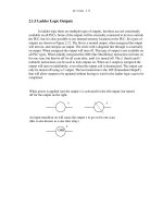
2.1.5 Ladder Logic Outputs
In ladder logic there are multiple types of outputs, but these are not consistently
available on all PLCs. Some of the outputs will be externally connected to devices outside
the PLC, but it is also possible to use internal memory locations in the PLC. Six types of
outputs are shown in Figure 2.12. The first is a normal output, when energized the output
will turn on, and energize an output. The circle with a diagonal line through is a normally
on output. When energized the output will turn off. This type of output is not available on
all PLC types. When initially energized the OSR (One Shot Relay) instruction will turn on
for one scan, but then be off for all scans after, until it is turned off. The L (latch) and U
(unlatch) instructions can be used to lock outputs on. When an L output is energized the
output will turn on indefinitely, even when the output coil is deenergized. The output can
only be turned off using a U output. The last instruction is the IOT (Immediate OutpuT)
that will allow outputs to be updated without having to wait for the ladder logic scan to be
completed.
When power is applied (on) the output x is activated for the left output, but turned
An input transition on will cause the output x to go on for one scan
xx
OSR
x
(this is also known as a one shot relay)
off for the output on the right.
plc wiring - 2.13
Figure 2.12 Ladder Logic Outputs
2.2 A CASE STUDY
Problem: Try to develop (without looking at the solution) a relay based controller
that will allow three switches in a room to control a single light.
When the L coil is energized, x will be toggled on, it will stay on until the U coil
Some PLCs will allow immediate outputs that do not wait for the program scan to
L
U
IOT
end before setting an output. (Note: This instruction will only update the outputs using
is energized. This is like a flip-flop and stays set even when the PLC is turned off.
x
xx
the output table, other instruction must change the individual outputs.)
Note: Outputs are also commonly shown using parentheses -( )- instead of
the circle. This is because many of the programming systems are text
based and circles cannot be drawn.
plc wiring - 2.14
2.3 SUMMARY
• Normally open and closed contacts.
• Relays and their relationship to ladder logic.
• PLC outputs can be inputs, as shown by the seal in circuit.
• Programming can be done with ladder logic, mnemonics, SFCs, and structured
text.
• There are multiple ways to write a PLC program.
Solution: There are two possible approaches to this problem. The first assumes that any
one of the switches on will turn on the light, but all three switches must be off for the
light to be off.
switch 1
switch 2
switch 3
light
The second solution assumes that each switch can turn the light on or off, regardless of
the states of the other switches. This method is more complex and involves thinking
through all of the possible combinations of switch positions. You might recognize
this problem as an exclusive or problem.
switch 1
switch 1
switch 1
light
switch 2
switch 2
switch 2
switch 3
switch 3
switch 3
switch 1 switch 2 switch 3
Note: It is important to get a clear understanding of how the controls are expected to
work. In this example two radically different solutions were obtained based upon a
simple difference in the operation.
plc wiring - 2.15
2.4 PRACTICE PROBLEMS
1. Give an example of where a PLC could be used.
2. Why would relays be used in place of PLCs?
3. Give a concise description of a PLC.
4. List the advantages of a PLC over relays.
5. A PLC can effectively replace a number of components. Give examples and discuss some good
and bad applications of PLCs.
6. Explain the trade-offs between relays and PLCs for control applications.
7. Explain why ladder logic outputs are coils?
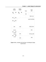
8. In the figure below, will the power for the output on the first rung normally be on or off? Would
the output on the second rung normally be on or off?
9. Write the mnemonic program for the Ladder Logic below.
2.5 PRACTICE PROBLEM SOLUTIONS
1. to control a conveyor system
2. for simple designs
3. A PLC is a computer based controller that uses inputs to monitor a process, and uses outputs to
100
101
201
plc wiring - 2.16
control a process. A simple program is used to set the controller behavior.
4. less expensive for complex processes, debugging tools, reliable, flexible, easy to expend, etc.
5. A PLC could replace a few relays. In this case the relays might be easier to install and less
expensive. To control a more complex system the controller might need timing, counting and
other mathematical calculations. In this case a PLC would be a better choice.
6. trade-offs include: cost, complexity, easy of debugging, etc.
7. the ladder logic outputs were modelled on relay logic diagrams. The output in a relay ladder
diagram is a relay coil. This is normally drawn as a circle.
8. off, on
9. LD 100, LD 101, OR, ST 201
2.6 ASSIGNMENT PROBLEMS
1. Develop a simple ladder logic program that will turn on an output X if inputs A and B, or input
C is on.
plc wiring - 3.1
3. PLC HARDWARE
3.1 INTRODUCTION
Many PLC configurations are available, even from a single vendor. But, in each of
these there are common components and concepts. The most essential components are:
Power Supply - This can be built into the PLC or be an external unit. Common
voltage levels required by the PLC (with and without the power supply) are
24Vdc, 120Vac, 220Vac.
CPU (Central Processing Unit) - This is a computer where ladder logic is stored
and processed.
I/O (Input/Output) - A number of input/output terminals must be provided so that
the PLC can monitor the process and initiate actions.
Indicator lights - These indicate the status of the PLC including power on, program
running, and a fault. These are essential when diagnosing problems.
The configuration of the PLC refers to the packaging of the components. Typical
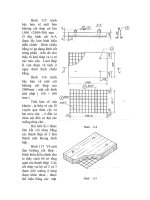
configurations are listed below from largest to smallest as shown in Figure 3.1.
Rack - A rack is often large (up to 18” by 30” by 10”) and can hold multiple cards.
When necessary, multiple racks can be connected together. These tend to be the
highest cost, but also the most flexible and easy to maintain.
Mini - These are similar in function to PLC racks, but about half the size.
Shoebox - A compact, all-in-one unit (about the size of a shoebox) that has limited
expansion capabilities. Lower cost, and compactness make these ideal for small
applications.
Micro - These units can be as small as a deck of cards. They tend to have fixed
Topics:
Objectives:
• Be able to understand and design basic input and output wiring.
• Be able to produce industrial wiring diagrams.
• PLC hardware configurations
• Input and outputs types
• Electrical wiring for inputs and outputs
• Relays
• Electrical Ladder Diagrams and JIC wiring symbols
plc wiring - 3.2
quantities of I/O and limited abilities, but costs will be the lowest.
Software - A software based PLC requires a computer with an interface card, but
allows the PLC to be connected to sensors and other PLCs across a network.
Figure 3.1 Typical Configurations for PLC
3.2 INPUTS AND OUTPUTS
Inputs to, and outputs from, a PLC are necessary to monitor and control a process.
Both inputs and outputs can be categorized into two basic types: logical or continuous.
Consider the example of a light bulb. If it can only be turned on or off, it is logical control.
If the light can be dimmed to different levels, it is continuous. Continuous values seem
more intuitive, but logical values are preferred because they allow more certainty, and
simplify control. As a result most controls applications (and PLCs) use logical inputs and
outputs for most applications. Hence, we will discuss logical I/O and leave continuous I/O
for later.
Outputs to actuators allow a PLC to cause something to happen in a process. A
short list of popular actuators is given below in order of relative popularity.
Solenoid Valves - logical outputs that can switch a hydraulic or pneumatic flow.
Lights - logical outputs that can often be powered directly from PLC output
boards.
Motor Starters - motors often draw a large amount of current when started, so they
require motor starters, which are basically large relays.
Servo Motors - a continuous output from the PLC can command a variable speed
or position.
rack
mini
micro
plc wiring - 3.3
Outputs from PLCs are often relays, but they can also be solid state electronics
such as transistors for DC outputs or Triacs for AC outputs. Continuous outputs require
special output cards with digital to analog converters.
Inputs come from sensors that translate physical phenomena into electrical signals.
Typical examples of sensors are listed below in relative order of popularity.
Proximity Switches - use inductance, capacitance or light to detect an object logi-
cally.
Switches - mechanical mechanisms will open or close electrical contacts for a log-
ical signal.
Potentiometer - measures angular positions continuously, using resistance.
LVDT (linear variable differential transformer) - measures linear displacement
continuously using magnetic coupling.
Inputs for a PLC come in a few basic varieties, the simplest are AC and DC inputs.
Sourcing and sinking inputs are also popular. This output method dictates that a device
does not supply any power. Instead, the device only switches current on or off, like a sim-
ple switch.
Sinking - When active the output allows current to flow to a common ground. This
is best selected when different voltages are supplied.
Sourcing - When active, current flows from a supply, through the output device
and to ground. This method is best used when all devices use a single supply
voltage.
This is also referred to as NPN (sinking) and PNP (sourcing). PNP is more popu-
lar. This will be covered in more detail in the chapter on sensors.
3.2.1 Inputs
In smaller PLCs the inputs are normally built in and are specified when purchasing
the PLC. For larger PLCs the inputs are purchased as modules, or cards, with 8 or 16
inputs of the same type on each card. For discussion purposes we will discuss all inputs as
if they have been purchased as cards. The list below shows typical ranges for input volt-
ages, and is roughly in order of popularity.
12-24 Vdc
100-120 Vac
10-60 Vdc
12-24 Vac/dc