Understanding DC circuits by dale r patrick and stephen w fardo
Bạn đang xem bản rút gọn của tài liệu. Xem và tải ngay bản đầy đủ của tài liệu tại đây (20.57 MB, 543 trang )
www.TechnicalPdf.com
Understanding DC Circuits
www.TechnicalPdf.com
This page intentionally left blank
www.TechnicalPdf.com
Understanding DC Circuits
Dale R. Patrick
Stephen W. Fardo
Boston Oxford Auckland Johannesburg Melbourne New Delhi
www.TechnicalPdf.com
Newnes is an imprint of Butterworth-Heinemann.
Copyright © 2000 by Butterworth-Heinemann
-& A member of the Reed Elsevier group
All rights reserved.
No part of this publication may be reproduced, stored in a retrieval system, or transmitted in any
form or by any means, electronic, mechanical, photocopying, recording, or otherwise, without the
prior written permission of the publisher.
@
Recognizing the importance of preserving what has been written, Butterworth-Heinemann prints
~ its books on acid-free paper whenever possible.
GLmAi. Butterworth-Heinemann
supports the efforts of American Forests and the Global ReLeaf
~ program in its campaign for the betterment of trees, forests, and our environment.
Library of CongressCataloging-in-Publication Data
Patrick, Dale R.
Understanding DC Circuits / by Dale R. Patrick and Stephen W. Fardo.
p. cm.
Includes index. (alk. pbk.)
ISBN 0-7506-7110-6
1. Electric circuits-Direct current. I. Fardo, Stephen W.
II. Title.
TK7816.F295 1999
621.319'12-dc21
99-16983
CIP
British Library Cataloguing-in-Publication Data
A catalogue record for this book is available from the British Library.
The publisher offers special discounts on bulk orders of this book.
For information, please contact:
Manager of Special Sales
Butterworth-Heinemann
225 Wildwood Avenue
Woburn, MA 01801-2041
Tel: 781-904-2500
Fax: 781-904-2620
For information on all Butterworth-Heinemann publications available, contact our World Wide
Web home page at:
www.TechnicalPdf.com
Contents
XI
PREFACE
UNIT ONE
COURSE OBJECTIVES
XIII
PARTS LIST FOR EXPERIMENTS
XV
BASICS OF DC ELECTRONICS
Electronic Systems
1
1
2
4
Energy, Work, and Power
6
Structure of Matter
7
Unit Introduction
Unit Objectives
Important Terms
Self-Examination
11
Electrostatic Charges
12
Static Electricity
13
Self-Exam ination
13
Electric Current
14
Conductors
15
Insulators
15
Semiconductors
15
Current Flow
16
Electric Force (Voltage)
18
Resistance
19
Voltage, Current, and Resistance
20
Volts, Ohms, and Amperes
21
Self-Exam ination
22
Contents
www.TechnicalPdf.com
V
UNIT TWO
Components, Symbols, and Diagrams
23
Resistors
25
Schematics
28
Block Diagrams
29
Wiring Diagrams
29
Self-Examination
29
Electric Units
31
Scientific Notation
34
Self-Examination
35
Batteries
36
Self-Examination
40
Experimental Activities for DC Circuits
41
Tools and Equipment
42
Important Information
42
Lab Activity Troubleshooting and Testing
42
Experiment 1-1-Components, Equipment, and Symbols
48
Experiment 1-2-Resistor Color Code
53
Unit 1 Examination: Basics of DC Electronics
56
MEASURING VOLTAGE, CURRENT, AND RESISTANCE
Measuring Resistance
59
59
60
60
Self-Examination
64
Measuring Voltage
Measuring Current
65
67
Self-Examination
70
Parallel Circuit Measurements
72
Combination Circuit Measurements
72
Digital Meters
73
Self-Examination
74
Experiment 2-1-Measuring Resistance
76
Experiment 2-2-Measuring Voltage
Experiment 2-3-Measuring Current
80
85
Experiment 2-4-Familiarization with Power Supply
89
Unit 2 Examination: Measuring Voltage, Current, and Resistance
91
Unit Introduction
Unit Objectives
Important Terms
VI
Understanding DC Circuits
www.TechnicalPdf.com
UNITTHREE
OHMIS LAW AND ELECTRIC CIRCUITS
Unit Introduction
93
Unit Objectives
93
Important Terms
94
Use of Calculators
95
Ohm's Law
96
Self-Examination
98
Series Electric Circuits
99
Summary of Series Circuits
101
Examples of Series Circuits
101
Self-Examination
102
Parallel Electric Circuits
104
Summary of Parallel Circuits
106
Examples of Parallel Circuits
107
Self-Examination
109
Combination Electrical Circuits
110
Examples of Combination Circuits
111
Kirchhoff's Laws
113
Self-Examination
114
Power in Electric Circuits
115
Voltage Divider Circuits
117
Self-Examination
120
Maximum Power Transfer
121
Kirchhoff's Voltage Law Problems
122
Equivalent Circuits
125
Self-Examination
130
Experiment 3-1-Application of Ohm's Law
134
Experiment 3-2-Series DC Circuits
137
Experiment 3-3-Parallel DC Circuits
140
Experiment 3-4-Combination DC Circuits
143
Experiment 3-5-Power in DC Circuits
147
Experiment 3-6-Voltage Divider Circuits
150
Experiment 3-7-Kirchhoff 's Voltage Law
153
Experiment 3-8-Kirchhoff 's Current Law
155
Experiment 3-9-Superposition Method
157
Experiment 3-10-Thevinin Equivalent Circuits
159
Experiment 3-11-Norton Equivalent Circuits
162
Experiment 3-12-Maximum Power Transfer
164
Experiment 3-13-Bridge Circuits
166
Unit 3 Examination: Ohm's Law and Electric Circuits
169
Contents
www.TechnicalPdf.com
VII
UNIT FOUR
UNIT FIVE
UNIT SIX
VIII
MAGNETISM AND ELECTROMAGNETISM
Unit Introduction
173
Unit Objectives
173
Important Terms
174
Permanent Magnets
175
Magnetic Field Around Conductors
177
Magnetic Field Around a Coil
178
Self-Examination
179
Electromagnets
179
Ohm's Law for Magnetic Circuits
181
Domain Theory of Magnetism
181
Electricity Produced by Magnetism
182
Magnetic Effects
184
Self-Examination
185
Experiment 4-1-The Nature of Magnetism
186
Experiment 4-2-Electromagnetic Relays
188
Unit 4 Examination: Magnetism and Electromagnetism
190
ELECTRONIC INSTRUMENTS
Unit Introduction
193
Unit Objectives
193
Important Terms
194
Analog Instruments
195
Self-Examination
199
Comparison Instruments
206
CRT Instruments
206
Numerical Readout Instruments
208
Chart-Recording Instruments
Self-Examination
208
209
Unit 5 Examination: Electronic Instruments
210
INDUCTANCE AND CAPACITANCE
Unit Introduction
213
Unit Objectives
213
Important Terms
214
Inductance
215
Capacitance
215
Time-Constant Circuits
221
Self-Examination
224
Experiment 6-1-Time-Constant Circuits
228
Unit 6 Examination: Inductance and Capacitance
232
Understanding DC Circuits
www.TechnicalPdf.com
APPENDIX A
ELECTRONICS SYMBOLS
235
APPENDIX B
ELECTRIC SAFETY
239
APPENDIX C
ELECTRONIC EQUIPMENT AND PARTS SALES
243
APPENDIX D
SOLDERING TECHNIQUES
245
APPENDIX E
TROUBLESHOOTING
247
251
INDEX
Contents
www.TechnicalPdf.com
IX
This page intentionally left blank
www.TechnicalPdf.com
Preface
Understanding DC Circuits is an introductory text that provides coverage of the various topics in
the field of direct current (de) electronics. The key concepts presented in this book are discussed in
a simplified approach that greatly enhances learning. The use of mathematics is discussed clearly
through applications and illustrations.
Every unit is organized in a step-by-step progression of concepts and theory. Each unit begins with
a unit introduction and unit objectives. A discussion of important concepts and theories follows.
Numerous self-examinations with answers provided are integrated into each chapter to reinforce
learning. Experimental activities with components and equipment listed are included with each
unit to help students learn electronics through practical experimental applications. The final learning activity for each unit is a unit examination, which includes at least twenty objective, multiplechoice questions.
Definitions of important terms are presented at the beginning of each unit. Several appendices
appear at the end of the book to aid students in performing experimental activities. The expense of
the equipment required for the experiments is kept to a minimum. A comprehensive parts list is
provided, as is information on electronics distributors.
The experiments suggested are low-cost activities that can be performed in the home or a school
laboratory. They are very simple and easy to understand and emphasize troubleshooting concepts.
The experiments allow students to develop an understanding of the topics discussed in each unit.
They are intended as an important supplement to learning. Electronics can be learned experimentally at a low cost through completion of these labs. Appendices dealing with electronics symbols,
safety, and soldering are provided for easy reference.
This textbook is organized in an easy-to-understand format. It can be used to acquire a basic
understanding of electronics in the home, school, or workplace. The organization of the book
allows students to progress at their own pace in the study of electronics. As students progress, they
may wish to purchase various types of test equipment at varying degrees of expense.
Several supplemental materials are available to provide an aid to effective learning. These include
the following:
1. Instructor's Resource Manual-provides the instructor with answers to all
unit examinations and suggested data for experimental activities, including a
comprehensive analysis of each experiment.
2.
Instructor's TransparencyMasters--enlarged reproductions of selected illustrations
used in the textbook that are suitable for use for transparency preparation for class
presentations.
3. Instructor's Test Item File-provides the instructor with many objective, multiplechoice questions for use with each unit of instruction.
These supplements are extremely valuable for instructors organizing electronics classes. The complete instructional cycle, from objectives to evaluation, is included in this book. We hope you will
find Understanding DC Circuits easy to understand and that you are successful in your pursuit of
knowledge in an exciting technical area. Electronics is an extremely vast and interesting field of
study. This book provides a foundation for understanding electronics technology.
Dale R. Patrick
Stephen W. Fardo
Richmond, Kentucky
Understanding DC Circuits
www.TechnicalPdf.com
XI
This page intentionally left blank
www.TechnicalPdf.com
Course Objectives
Upon completion of this course on Understanding DC Circuits, you should be able to:
1. Understand the following basic electronics concepts:
a. Voltage
b. Current
c. Resistance
d. Power
e. Static electricity
f. Schematics
2. Use a multimeter to measure voltage, current, and resistance.
3. Solve basic electronics problems with dc circuits that involve calculation of
voltage, current, and resistance.
4. Understand basic concepts of magnetism and electromagnetism.
5. Describe the construction, operation, and use of common electronics instruments.
6. Explain the properties of inductance and capacitance in dc circuits.
7. Construct experimental dc circuits using schematics and perform tests and
measurements with a multimeter.
8. Understand basic safety rules and procedures involved in electronics applications.
9. Recognize common electronic components, symbols, and equipment.
10. Perform soldering operations to connect electronic components to circuit
boards.
Preface
www.TechnicalPdf.com
XIII
This page intentionally left blank
www.TechnicalPdf.com
Parts List for Experiments
Various components and equipment are needed to perform the experimental activities in this
course. These parts may be obtained from electronics suppliers, mail-order warehouses, or educational supply vendors. A list of several of these is included in appendix C.
These parts may be obtained through a variety of electronics suppliers. As a rule, a standard part
number is used to obtain parts. In many cases, however, many other manufacturers make an
equivalent part.
The following equipment and components are necessary for successful completion of the activities
included in this book:
RESISTORS
2 100 Q, %W, 5% (brown-black-brown-gold)
2 1000 Q, 'h W, 5% (brown-black-red-gold)
2 10 kQ, %W, 5% (brown-black-orange-gold)
1 1 MQ, %W, 5% (brown-black-green-gold)
1 1200 Q, %W, 5% (brown-red-red-gold)
1 200 Q, %W, 5% (red-black-brown-gold)
1 2000 Q, %W, 5% (red-black-red-gold)
1 22 kQ, %W,5 % (red-red-orange-gold)
1 240 Q, %W, 5% (red-yellow-brown-gold)
1 300 Q, 'h W, 5% (orange-black-brown-gold)
1 390 Q, %W, 5% (orange-white-brown-gold)
1 510 Q, %W, 5% (green-brown-brown-gold)
1 750 Q, %W, 5% (violet-green-brown-gold)
1 910 Q, %W, 5% (white-brown-brown-gold)
1 470 Q, %W, 5% (yellow-violet-brown-gold)
1 68 Q, %W, 5% (blue-gray-black-gold)
1 68 kQ, %W, 5% (blue-gray-orange-gold)
1 100 Q, 2 W, 5% (brown-black-brown-gold)
2 100 Q, 1 W, 5% (brown-black-brown-gold)
1 15 Q, %W, 5% (brown-green-black-gold)
1 22 Q , %W, 5% (red-red-black-gold)
1 220 Q, 2 W, 5% (red-red-brown-gold)
1 2200 Q, %W, 5% (red-red-red-gold)
1 220 kQ, %W, 5% (red-red-yellow-gold)
1 33 kQ, %W, 5% (orange-orange-orange-gold)
1 4700 Q, %W, 5% (yellow-violet-red-geld)
1 5100 Q, %W, 5% (green-brown-red-gold)
Understanding DC Circuits
www.TechnicalPdf.com
XV
CAPACITORS (ELECTROLYTIC)
1 10 JlF, 35V
1 47 JlF, 35V
MISCELLANEOUS
1 solder package
10 feet of no. 22 solid wire
1 compass
1 6 V light bulb
1 light socket
1 permanent magnet
1 small-parts container
1 6 V battery
2 1.5 V dry cells
1 200
n linear potentiometer
1 slide switch (DPDT)
1 relay
XVI
Preface
www.TechnicalPdf.com
UNIT
1
Basics of DC Electronics
Electronics is a fascinating science that we use in many different ways. It is
difficult to count the many ways in which we use electronics each day. It
is important for everyone today to understand electronics.
This unit deals with the most basic topics in the study of electronics. These
include basic electric systems, energy and power, the structure of matter,
electric charges, static electricity, electric current, voltage, and resistance.
This unit and other units have definitions of important terms at the beginning. Preview these terms to gain a better understanding of what is discussed in the unit. As you study the unit, return to the definitions whenever
the need arises. There are also self-examinations throughout the unit and a
unit examination at the end of each unit. These will aid in understanding
the material in the unit. Several experiments are suggested at the end of
each unit. They may be completed in a laboratory or at home at low cost.
UNIT OBJECTIVES
Upon completing this unit, you will be able to do the following:
1. Explain the composition of matter.
2. Explain the laws of electric charges.
3. Define the terms insuletor, conductor, and semiconductor.
4. Explain electric current flow.
5. Diagram a simple electric circuit.
6. Identify schematic electronic symbols.
7. Convert electric quantities from metric units to English units and
English units to metric.
8. Use scientific notation to express numbers.
9. Define voltage, current, and resistance.
10. Describe basic types of batteries.
Basics of DC Electronics
www.TechnicalPdf.com
1
11. Connect batteries in series, parallel, and combination configurations.
12. Explain the purposes of different configurations
of battery connections.
13. Explain factors that determine resistance.
14. Identify different types of resistors.
15. Identify resistor value according to color code
and size.
16. Explain the operation of potentiometers (variable resistors).
17. Construct basic electronic circuits.
Important Terms
Before reading this unit, review the following terms.These terms provide a basic understanding of some of the concepts discussed. As you
read other units, you may find it necessary to review these terms.
Ampere (A) The unit of electric charge, which is the basic unit of
measurement for current flow in an electric circuit.
Atom The smallest particle to which an element can be reduced
and still retain its characteristics.
Atomic number The number of particles called protons in the
nucleus (center) of an atom.
Closed circuit A circuit that forms a complete path so that electric
current can flow through it.
Compound The chemical combination of two or more elements
to make an entirely different material.
Conductor A material that allows electric current to flow
through it easily.
Control The part of an electric system that affects what the system
does; a switch to turn on and turn off a light is a type of control.
Conventional current flow Current flow assumed to be in a
direction from high charge concentration (+) to low charge
concentration (-).
Coulomb (C) A unit of electric charge that represents a large
number of electrons.
Current The movement of electric charge; the flow of electrons
through an electric circuit.
2
UNIT 1
www.TechnicalPdf.com
Electromotive force (EMF) The pressure, or force, that causes
electric current to flow.
Electron An atomic particle said to have a negative (-) electric
charge; electrons are the means by which the transfer of electric
energy takes place.
Electron current flow Current flow assumed to be in the direction of electron movement from a negative (-) potential to a positive (+) potential.
Electrostatic field The space around a charged material in which
the influence of the electric charge is experienced.
Element The basic materials that make up all other materials;
they exist by themselves (such as copper, hydrogen, carbon) or in
combination with other elements (water is a combination of the
elements hydrogen and oxygen).
Energy The capacity to do work.
Free electrons Electrons located in the outer orbit of an atom
that are easily removed and result in flow of electric current.
Indicator The part of an electric system that shows whether the
system is on or off or that a specific quantity is present.
Insulator A material that offers a high resistance to electric current flow.
Kinetic energy Energy that exists because of movement.
Load The part of an electric system that converts electric energy
into another form of energy, such as an electric motor that converts electric energy into mechanical energy.
Matter Any material that makes up the world; anything that
occupies space and has weight; a solid, a liquid, or a gas.
Metallic bonding The method by which loosely held atoms are
bound together in metals.
Molecule The smallest particle to which a compound can be
reduced before being broken down into its basic elements.
Neutron A particle in the nucleus (center) of an atom that has no
electric charge, or is neutral.
Nucleus The core, or center part, of an atom; contains protons
that have a positive charge and neutrons that have no electric
charge.
Ohm (Q) The unit of measurement of electric resistance.
Open circuit A circuit that has a broken path so that no electric
current can flow through it.
Orbit The path along which electrons travel around the nucleus
of an atom.
Orbital Areas through which electrons move; designated as s, p,
d, and f.
Basics of DC Electronics
www.TechnicalPdf.com
3
Path The part of an electric system through which electrons
travel from a source to a load, such as the electric wiring used in
a building.
Potential energy Energy that exists because of position.
Power The rate at which work is done.
Proton A particle in the center of an atom that has a positive (+)
electric charge.
Resistance (R) The opposition to the flow of electric current in a
circuit; its unit of measurement is the ohm (0).
Semiconductor A material that has a value of electric resistance
between that of a conductor and an insulator and is used to manufacture solid-state devices such as diodes and transistors.
Short circuit A circuit that forms a direct path across a voltage
source so that a very high and possibly unsafeelectric current flows.
Source The part of an electric system that supplies energy to
other parts of the system, such as a battery that suppl ies energy
for a flashlight.
Stable atom An atom that does not release electrons under normal conditions.
Static charge A charge on a material that is said to be either positive or negative.
Static electricity Electricity at rest caused by accumulation of
either positive or negative electric charge.
Valence electrons Electrons in the outer orbit of an atom.
Volt (V) The unit of measurement of electric potential.
Voltage Electric force, or pressure, that causes current to flow in
a circuit.
Watt (W) The unit of measurement of electric power.
Work The transforming or transferring of energy.
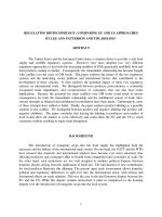
Electronic Systems
A simple electronic system block diagram and pictorial diagram
are shown in Fig. 1-1. Using a block diagram allows a better
understanding of electronic equipment and provides a simple
way to "fit pieces together." The system block diagram can be
used to simplify many types of electronic circuits and equipment.
The parts of an electronic system are the source/ path/ control/
load/ and indicator. The concept of electronic systems allows discussion of some complex things in a simplified manner. This
method is used to present much of the material in this book to
make it easier to understand.
4 UNIT 1
www.TechnicalPdf.com
Indicator
(optional)
(a)
Load
Indicator
Source
Path
(wire)
(b)
FIGURE 1-1 Electronicsystem. (a) Blockdiagram.
(b) Pictorial diagram.
The systems concept serves as a big picture in the study of
electronics. In this way a system can be divided into a number of
parts. The role played by each part then becomes clearer. It is
easy to understand the operation of a complete electronic system. When one knows the function of a system, it is easier to
understand the operation of each part. In this way, it is possible to
see how the pieces of any electronic system fit together to make
something that operates.
Each block of an electronic system has an important role to
play in the operation of the system. Hundreds and even thousands of components sometimes are needed to form an electronic system. Regardless of the complexity of the system, each
block must achieve its function when the system operates.
The source of an electronic system provides electric energy for
the system. Heat, light, chemical, and mechanical energy may be
used as sources of electric energy.
The path of an electronic system is simple compared with
other system parts. This part of the system provides a path for the
transfer of energy. It starts with the energy source and continues
through the load. In some cases this path is a wire. In other systems a complex supply line is placed between the source and the
load, and a return line from the load to the source is used. There
usually are many paths within a complete electronic system.
The control section of an electronic system is the most complex part of the system. In its simplest form, control is achieved
when a system is turned on or off. Control of this type takes place
anywhere between the source and the load. The term full control
is used to describe this operation. A system also may have some
type of partial control. Partial control causes some type of operational change in the system other than turning it on or off. A
change in the amount of current flow is a type of change
achieved by means of partial control.
The load of an electronic system is the part or group of parts
that do work. Work occurs when energy goes through a transformation or change. Heat, light, and mechanical motion are forms
of work produced by loads. Much of the energy produced by the
source is changed to another type by the load. The load usually is
the most obvious part of the system because of the work it does.
An example is a light bulb, which produces light.
The indicator of an electronic system displays a particular operating condition. In some systems the indicator is an optional part
that is not really needed. In other systems it is necessaryfor proper
operation. In some cases adjustments are made with indicators. In
other cases an indicator is attached temporarily to the system to
make measurements. Test lights, panel meters, oscilloscopes, and
chart recorders are common indicators used in electronic systems.
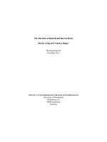
Example of a System
Nearly everyone has used a flashlight. This device is designed
to serve as a light source. A flashlight is a very simple type of
electronic system. Figure 1-2 is a cutaway drawing of a flashlight
with each part shown.
The battery of a flashlight serves as the energy source of the
system. Chemical energy in the battery is changed into electric
energy to cause the system to operate. The energy source of a
Basics of DC Electronics
www.TechnicalPdf.com
5
flashlight-the battery-may be thrown away.
Batteries are replaced periodically when they lose
their ability to produce energy.
The path of a flashlight is a metal case or a small
metal strip. Copper, brass, or plated steel is used as
the path.
The control of electric energy in a flashlight is
achieved by means of a slide switch or push-button
switch. This type of control closes or opens the path
between the source and the load device. Flashlights
have only a means of full control, which is operated
manually by a person.
The load of a flashlight is a small lamp bulb. When electric
energy from the source passes through the lamp, the lamp produces a bright glow. Electric energy is changed into light energy.
The lamp does a certain amount of work when this energy
change takes place.
Flashl ights do not have an indicator as part of the system.
Operation is indicated, however, when the lamp produces light.
The load of this system also acts as an indicator. In many electronic systems, the indicator is an optional part.
Energy, Work, and Power
An understanding of the terms energy, work, and power is necessary in the study of electronics. Energy means the capacity to do
work. For example, the capacity to light a light bulb, to heat a
home, or to move something requires energy. Energy exists in
many forms, such as electric, mechanical, chemical, and thermal. If energy exists because of the movement of an object, such
as a ball rolling down a hill, it is called kinetic energy. If it exists
because the object is in position, such as a ball at the top of the
hill but not yet rolling, it is called potential energy. Energy has
become one of the most important factors in our society.
The second important term is work. Work is the transferring or
transforming of energy. Work is done when a force is exerted to
move something over a certain distance against opposition. Work
is done when a chair is moved from one side of a room to the
other. An electric motor used to drive a machine performs work.
When force is applied to open a door, work is performed. Work is
performed when motion is accomplished against the action of a
force that tends to oppose the motion. Work also is done each
time energy changes from one form into another.
The third important term is power. Power is the rate at which
work is done. It involves not only the work performed but also
the amount of time in which the work is done. For example, electric power is the rate at which work is done as electric current
flows through a wire. Mechanical power is the rate at which work
is done as an object is moved against opposition over a certain
distance. Power is either the rate of production or the rate of use
of energy. The watt (W) is the unit of measurement of power.
6
UNIT 1
www.TechnicalPdf.com
Metalcase and
spring
Lamp is
on
Sliding
switch
or off
Incandescent
lamp
FIGURE 1-2 Cutaway drawingof a flashlight.
Structure of Matter
In the study of electronics, it is necessaryto understand why electric energy exists. To gain this understanding, one must first look
at how certain natural materials are made. It is then easier to see
why electric energy exists.
Some basic scientific terms are often used in the study of chemistry. They also are important in the study of electronics. Matter is
anything that occupies space and has weight. Matter can be a
solid, a liquid, or a gas. Solid matter includes such things as metal
and wood; liquid matter is exemplified by water or gasoline; and
gaseous matter includes things such as oxygen and hydrogen.
Solids can be converted into liquids, and liquids can be made into
gases. For example, water can be a solid in the form of ice. Water
also can be a gas in the form of steam. The difference is that the
particles of which the substances are made move when heated. As
they move, the particles strike one another and move farther
apart. Ice is converted into a liquid by means of adding heat. If
heated to a high temperature, water becomes a gas. All forms of
matter exist in their most familiar forms because of the amount of
heat they contain. Some materials require more heat than others
to become liquids or gases. However, all materials can be made
to change from a solid to a liquid or from a liquid to a gas if
enough heat is added. These materials also can change into liquids or solids if heat is taken from them.
The next important term in the study of the structure of matter
is element. An element is considered to be the basic material that
makes up all matter. Materials such as hydrogen, aluminum, copper, iron, and iodine are a few of the more than 100 elements
known to exist. A table of elements is shown in Fig. 1-3. Some
elements exist in nature and some are manufactured. Everything
around us is made of elements.
There are many more materials in our world than there are elements. Materials are made by means of combining elements. A
combination of two or more elements is called a compound. For
example, water is a compound made from the elements hydrogen and oxygen. Salt is made from sodium and chlorine.
Another important term is the molecule. A molecule is said to
be the smallest particle to which a compound can be reduced
before breaking down into its basic elements. For example, one
molecule of water has two hydrogen atoms and one oxygen
atom. Within each molecule one finds particles called atoms.
Within these atoms are the forces that cause electric energy to
exist. An atom is considered to be the smallest particle to which
an element can be reduced and still have the properties of that
element. If an atom were broken down any further, the element
would no longer exist. The smallest particles in all atoms are
called electrons, protons, and neutrons. Elements differ from one
Basics of DC Electronics 7
www.TechnicalPdf.com
CD
s
==i
"""'"
Element
Actinium
Aluminum
Americium
Antimony
Argon
Symbol
Ac
AI
Am
Sb
Ar
Atomic
no.
89
13
95
51
18
Atomic
weight
227*
26.97
243*
121.76
39.944
Element
Hafnium
Hahmium
Helium
Holmium
Hydrogen
Symbol
Hf
Ha
He
Ho
H
Atomic
no.
72
105
2
67
1
www.TechnicalPdf.com
Atomic
weight
178.6
262*
4.003
164.94
1.0080
Element
Praseodymium
Promethium
Protactinium
Redium
Rodon
Symbol
Pr
Pm
Pa
Ra
Rn
Atomic
no.
59
61
91
88
86
Atomic
weight
140.92
145*
231*
226.05
222