Summary of chemistry doctoral thesis: Study on synthesis, characteristics, and adsorption properties of toxic organic substances in the water environment of mesoporous carbon materials
Bạn đang xem bản rút gọn của tài liệu. Xem và tải ngay bản đầy đủ của tài liệu tại đây (924.56 KB, 28 trang )
MINISTRY OF EDUCATION
VIETNAM ACADEMY OF
AND TRAINING
SCIENCE AND TECHNOLOGY
GRADUATE UNIVERSITY OF SCIENCE AND TECHNOLOGY----------------------------
NGUYEN THI HONG HOA
STUDY ON SYNTHESIS, CHARACTERISTICS AND
ADSORPTION PROPERTIES OF TOXIC ORGANIC
SUBSTANCES IN THE WATER ENVIRONMENT OF
MESOPOROUS CARBON MATERIALS
Major: Theoretical Chemistry and Physical Chemistry
Code
: 62.44.01.19
SUMMARY OF CHEMISTRY DOCTORAL THESIS
Ha Noi – 2019
The work was completed at: Graduate Universty of Science and
Technology - Vietnam Academy of Science and Technology.
Science supervisor 1: Assoc.Prof.Dr. Dang Tuyet Phuong
Science supervisor 2: Dr. Tran Thi Kim Hoa
Reviewer 1: …
Reviewer 2: …
Reviewer 3: ….
The thesis will be defended in front of doctoral thesis, held at the
Graduate University Science and Technology - Vietnam Academy
of Science and Technology at ... o’clock, on day ... month ... year
2019.
Thesis can be found at:
- Library of the Graduate University Science and Technology
-
National
Library
of
Vietnam
1
INTRODUCTION
1. The necessity of the thesis
Mesoporous carbon materials have an ordered structure,
uniform pore size. They often were synthesized by two methods:
soft-templating and hard-templating. With the soft-templating
method, materials have been prepared via self-assembly by using
soft-templating (surfactant). The obtained materials have less orderly
structure. The pore size of the material is difficult to control and the
template is difficult to remove. With the hard-templating method,
MCM-48, SBA-15, etc. are used as the templates. The materials have
highly order structure, uniform and easily controlled pore size.
Therefore, hard-templating method is used more widely. However,
the pore size of materials is smaller than that of the hard-templates
because obtained materials are inverse copies of the templates.
The thickness of the wall and the pore size are limited by size and
shape form of hard-templates. So far, the pore size of mesoporous
carbon materials are synthesized by hard-templating method only
reach the maximum of ~ 5.5 nm. The increasing in pore size is not
feasible because it is limited by the size of the templates, resulting in
framework collapse and pore breakage due to decrease stability.
Hence, it is necessary to find new methods to synthesize mesoporous
carbon materials with larger sizes, higher stability.
Mesoporous carbon materials are said to be a good adsorbent
of organic substances in water environment. However, these
materials are not stability. The structure of the materials is easily
broken during the reuse process and it is difficult to recover. So, the
regeneration and reuse of mesoporous carbon materials are very
difficult. Because of, if heat is used to remove completely adsorbed,
2
it is necessary to perform high temperature causing to burn
mesoporous carbon materials. Also, the solvents are used to remove
the adsorbed, resulting less-economical effect and secondary
pollution. Therefore, the research to find the effective and feasible
methods for regeneration and reuse of mesoporous carbon materials
is necessary.
From the above reasons, the thesis topic “Study on synthesis,
characteristics, and adsorption properties of toxic organic
substances in the water environment of mesoporous carbon
materials” was studied.
2. The purpose of the thesis
Study on control the process of synthesizing mesoporous
carbon materials with an ordered structure, large pore size, high
stability. They are as an effective adsorbent for toxic organic
substances with different molecular sizes in water environment.
Synthesis of mesoporous carbon materials with desired order
structure, large pore size, high durability for effective adsorption of
different molecular size toxic organic substances in water
environment.
3. Scientific and practical significance of the thesis
The thesis has found a new method to increase the pore size
of mesoporous carbon by filling the liquid glass into the pore of the
template (silica SBA-15) before impregnating the carbon presource
to limit the penetration of carbon sealed the pore system of SBA-15.
Stability of mesoporous carbon is increases due to silicon are
partially retained in materials. This technique opens the way of
synthesis of mesoporous carbon as an adsorbent with a desired pore
size and stability.
3
Doping iron into the framework of mesoporous carbon
materials creates catalysts to decompose adsorbed, release the
adsorption sites, regeneration and reuse of mesoporous carbon,
extend the scope of application of materials for treatment of toxic
organic substances in water.
4. New findings of the thesis
1. For the first time, a new technique is used to control the
pore size of the mesoporous carbon materials which is synthesized
by hard – temlating method by filling the liquid glass into the pore of
SBA-15 before impregnating the carbon source to prevent
penetration carbon to seal the pore system of SBA-15. This
technique opens new direction for mesoporous carbon synthesis
technologies as the adsorbent with the desired pore size.
2. Retaining a silicon part in synthesiszed material to
increase the stability of the mesoporous carbon material.
3. Using atom-planting method to put iron into framework of
the mesoporous carbon material do not change the structure of the
materials. Iron exists on the surface of materials in the highly
dispersed Fe2O3 and FeO forms, favorable for adsorption and
decomposition of
methylene
blue,
enhance
the
ability of
regeneration, reuse and do not cause secondary pollution.
5. The structure of the thesis
The thesis consists of 140 pages with 83 figures, 31 tables.
The thesis includes the following sections: Introduction (2 pages);
Chapter 1: Overview (44 pages); Chapter 2: Research methods and
experiment (16 pages); Chapter 3: Results and discussion (59 pages);
Conclusions(2 pages); Novel scientific contributions of the thesis;
List of publications; References and appendices.
4
CHAPTER 1. OVERVIEW
Chapter 1 includes a general introduction of synthesis methods,
application of mesoporous carbon materials and metal containing
mesoporous carbon. Mesoporous carbon materials are synthesized by
two methods: soft-templating and hard-templating. Metal containing
mesoporous carbon materials are synthesized by two methods:
impregnation and atom-planting. In this chapter, adsorption
properties, application and adsorption mechanism of mesoporous
carbon materials in the field of adsorption were introduced.
CHAPTER 2. RESEARCH METHODS AND EXPERIMENT
2.1. Chemistry
- F127 (Sigma-Aldrich); Phenol (China); Focmaldehit (China); SBA15, MCF (Synthesis from liquid glass - Department of Surface
Chemistry - Institute of Chemistry - Vietnam Academy of Science
and Technology); Refined sugar (Vietnam); Liquid glass (Vietnam).
2.2. Synthesis of materials
2.2.1. Synthesis of mesoporous carbon
- Soft–templating method:
Template F127; pH = 1, 2, 3;
Temperature: 80 oC, 100 oC, 120 oC.
- Hard-templating method:
Templates of SBA-15 or MCF;
Number of impregnations: 1, 2, 3;
Figure 2.3. Process of synthesizing mesoporous carbon
The CMQTBC(TTL) pattern is synthesized using a hard-templating
method, but the liquid glass is filled into the pore of SBA-15 before
impregnating the carbon source.
5
Table 2.2. Samples of mesoporous carbon
1
Materials
Method
CMQTBM1
T (oC) N1
3
Templating
N2
1
100
-
F127
-
2
100
-
F127
-
3
100
-
F127
-
2
80
-
F127
-
CMQTBM120
2
120
-
F127
-
CMQTBC1(SBA-15)
-
-
1
SBA-15
0
CMQTBC2(SBA-15);CMQTBC(SBA-15)
-
-
2
SBA-15
0
-
-
3
SBA-15
0
-
-
2
MCF
0
-
-
2
SBA-15
4
-
-
2
SBA-15
4
-
-
2
SBA-15
4
CMQTBM2; CMQTBM100
Soft-
CMQTBM3
templating
CMQTBM80
CMQTBC3(SBA-15)
Hard-
CMQTBC(MCF)
templating
CMQTBC(TTL)
Fe-t-CMQTBC(TTL) (Impregnation)
Fe-b-CMQTBC(TTL) (Atom-planting)
1
pH
2
2
3
Temperature; Number of impregnation; Number of g Na2SiO3
6
2.2.2. Synthesis of iron containing mesoporous carbon
- Synthesis of Fe-t-CMQTBC(TTL) by impregnating iron nitrate 0.2
M (6% mass of Fe).
- Synthesis of Fe-b-CMQTBC(TTL) by the atom-planting method.
2.3. Characterizations
- Characterization techniques: XRD, SEM, TEM, BET, EDX, TA,
FTIR, XPS.
2.4. Determination of the isoelectric point of mesoporous carbon
2.5. Determination of adsorption properties
Langmuir, Freundlich adsorption isotherm models
The pseudo-fisrt-order and pseudo-second-order adsorption
kinetic models
2.6. Method of evaluating the ability to reuse materials
Recover the material after adsorption and wash with water
and ethanol + methanol (methanol and ethanol 1: 2 ratio, V = 60 ml)
stir for 2 hours at 60 ° C. Then, the material is used to adsorb MB
CHAPTER 3. RESULTS AND DISCUSSION
3.1. Synthesis of mesoporous carbon
3.1.1. Soft-templating method
*) Effect of temperature 80 oC, 100 oC, 120 oC:
Figure 3.1; 3.2. XRD patterns (A) and nitrogen adsorptiondesorption isotherms (B) of mesoporous carbon are synthesized at
different temperatures
7
Temperature increase → Brown motion increases → Selfassembly of surfactants increase → The length of the hydrophobic
chain increases → pore size increases. Temperature high (over 100
C) → evaporate water, flocculate surfactants → pore size decreases.
o
So, the optimal synthetic temperature is 100 oC.
*) Effect of pH = 1, 2, 3:
Figure 3.5; 3.6. XRD patterns (A) and Nitrogen adsorptiondesorption
isotherms
(B)
of
CMQTBM1,
CMQTBM2
and
CMQTBM3
The zero charge point of silicon is 2, if pH = 2, mesoporous
carbon materials are formed according to the correct mechanism
S0H+X− I (S: F127, X− Cl−; I: Si)
Thus, conditions of suitable syntheting of materials are at
100 °C and pH = 2, the obtained materials have a mesoporous
structure with pore size of 5.4 nm, surface area BET of 1693 m2/g .
3.1.2. Hard-templating method
3.1.2.1. Templating: using two templating with the same hexagonal
structure, but the pore size of MCF is larger than that of SBA-15.
Figure 3.9; 3.10. XRD patterns of SBA-15; CMQTBC(SBA-15) (A)
and MCF; CMQTBC(MCF) (B)
8
XRD pattern shows that the structure of CMQTBC(SBA-15)
and CMQTBC(MCF) is similar to that of SBA-15 and MCF.
Figure
3.11.
TEM
images
of
CMQTBC(SBA-15)
and CMQTBC(MCF)
The structure of CMQTBC(SBA-15) and CMQTBC(MCF)
samples have a hexagonal structure and uniform pore size (Figure
3.11 and 3.12). The pore size of CMQTBC(MCF) is larger than that
of CMQTBC(SBA-15) because of the pore size of MCF is larger
than that of SBA-15.
Figure 3.12. Nitrogen adsorptiondesorption isotherms CMQTBC(SBA15) and CMQTBC(MCF)
Figure 3.12 shows that both
CMQTBC(SBA-15)
and
CMQTBC(MCF) belong to type IV
isotherm with a hysteresis. The pore
sizes of CMQTBC(SBA-15) and CMQTBC(MCF) are in the range
of respectively 4.2 nm; 5.6 nm.
Figure 3.13. TGA patterns of CMQTBC(SBA-15) (A) and
CMQTBC(MCF) (B)
9
TGA
data
show
that
CMQTBC(SBA-15)
(complete
o
combustion temperature of 595 C) has higher thermal stability than
CMQTBC(MCF) (552 oC) does. Therefore, SBA-15 is selected as
templating to synthesize mesoporous carbon materials.
3.1.2.2. Amount (number of impregnation) of carbon source
Figure 3.14. XRD patterns of
SBA-15,
CMQTBC1(SBA-15),
CMQTBC2(SBA-15)
and
CMQTBC3(SBA-15)
Figure 3.14 shows that
all three materials CMQTBC1(SBA-15), CMQTBC2(SBA-15) and
CMQTBC3(SBA-15) with the respective impregnated sample l, 2
and 3 times the carbon precursor have characteristics of mesoporous
materials which are similar to those of SBA-15 material.
Figure 3.15. Nitrogen
adsorption-desorption
isotherms (A) and pore
size distributions (B) of
SBA-15,
CMQTBC1(SBA-15),
CMQTBC2(SBA-15)
and
CMQTBC3(SBA-
15)
Figure 3.15A shows that all four samples SBA-15,
CMQTBC1(SBA-15), CMQTBC2(SBA-15) and CMQTBC3(SBA15) belong to type IV isotherm with a hysteresis which are typical for
10
mesoporous materials. Figure 3.15B shows that the pore distribution
of CMQTBC2(SBA-15) is the narrowest with the pore size
concentrated mainly in the 4-5 nm range. Thus, the most number of
impregnated carbon precursor is 2.
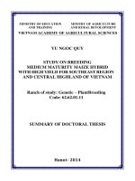
3.1.2.3. Controlling pore size
We use silicon from liquid glass to fill the pore of SBA-15
before impregnating the carbon precursor and prevent carbon from
penetrating into the pore. Then the silicon is removed by HF and the
obtained mesoporous carbon materials have the pore system larger
than that of the initial SBA-15 (Figure 3.19).
Figure 3.19. Simulate the synthesis process of CMQTBC(TTL)
Figure
3.16.
XRD
pattern
of
CMQTBC(TTL)
Figure 3.16 shows that CMQTBC(TTL)
has a peak at very low scanning angle (below
0.5o), outside the detection threshold of the meter.
Due to the small angle θ, a large distance d can be predicted, leading
to large pore size.
Figure
3.17.
Nitrogen
adsorption-desorption
isotherms (A) and pore size
distributions (B) of SBA-15,
CMQTBC(SBA-15)
CMQTBC(TTL)
and
11
Figure 3.18. TEM images of
CMQTBC(SBA-15) (A) and
CMQTBC(TTL) (B).
Figure 3.17 and 3.18
show that CMQTBC (TTL) has a large pore size (10.4 nm), fairly
uniform pore. This result is consistent with the XRD analysis data.
The synthesis process consists of stages (Figure 3.19): Stage
1: mixing liquid glass and SBA-15 templating obtain SBA-15(TTL)
with pore of SBA-15 filled by liquid glass. Stage 2: impregnating
carbon precursor onto SBA-15(TTL) and carbonization obtained CSiO2 material. Stage 3: C-SiO2 is washed with HF 10% for the first
time to obtain C3 material. Stage 4: C3 is washed with HF 10% for
the second time to obtain CMQTBC(TTL) material. Stage 5:
washing CMQTBC(TTL) with HF 10% 3 times obtain C5 material.
Table 3.6. The characteristic parameter for porous properties of
SBA-15(TTL), C-SiO2, C3 (washing HF 1st), CMQTBC(TTL)
(washing HF 2nd) và C5 (washing HF 3rd).
Materials
SBET (m2/g) Vpore (cm3/g) D (nm)
SBA-15
493
0,941
7,6
SBA-15(TTL)
1,4
0,008
27,7
C-SiO2
47,4
0,087
8,7
C3
221
0,486
11,0
CMQTBC(TTL)
772
1,698
10,4
C5
1276
4,304
15,0
From table 3.6 shows CMQTBC(TTL), is washed 2 times by
HF, has a surface area SBET (772 m2/g) and a porosity Vpore (1,698
cm3/g) higher than material is no washing or washing 1 time. After
the 3rd washing (C5 sample), Si is completely removed, the surface
12
area SBET and porosity Vpore increase to 1276 cm3/g and 4.304 cm3/g
respectively because silicon was further removed, causing the
expanding of pore, increasing in the average pore volume but the
structure is less stable and the signs of structural collapse occur
(Figure 3.21).
Figure 3.21. SEM images of
CMQTBC(TTL) and C5
Figure 3.23. TGA pattern of
Figure 3.24. XPS spectra of
CMQTBC(TTL)
Figure
3.23
CMQTBC(TTL)
shows
that
CMQTBC(TTL)
(complete
o
combustion temperature of 605 C) has higher thermal stability than
CMQTBC(SBA-15) (559 oC).
XPS spectra (Figure 3.24) show the peaks at the energy level
of 103 eV; 285 eV; 530 eV which are assigned to the presence of
Si2p; C1s, O1s in CMQTBC(TTL) materials.
Thus, with the technique of using pore-filled liquid glass
SBA-15, synthesized MC material with large pore size (10.4 nm),
surface area (772 m2/g) and high pore volume (1.603 cm3/g).
Sumary:
For soft-templating method: conditions of suitable synthetic
materials are at 100 oC, pH = 2. The obtained materials have a
13
mesoporous structure with a pore size of 5.4 nm, porous
characteristics, and BET surface area of 1693 m2/g. The order of
materials is not high.
For hard-templating method:
- Suitable conditions for synthesizing materials: SBA-15 is
template and number of impregnation is 2;
- It is possible to change the pore size of materials by using
different templates with different pore sizes such as SBA-15 and
MCF.
- filling the liquid glass into the pore of SBA-15 before
impregnating the carbon source to prevent penetration carbon to
seal the pore system of SBA-15 resulting the adsorbent with the
desired pore size.is a new technique that has never been reported in
the literature.
- Stability of the mesoporous carbon materials increases due
to retaining a part of silicon in the material.
3.2. Synthesis of iron containing mesoporous carbon
Figure 3.25. XRD patterns of
Fe-t-CMQTBC(TTL) and Fe-bCMQTBC(TTL)(
small
corners)
Figure 3.26. XRD patterns of
Fe-t-CMQTBC(TTL) and Fe-bCMQTBC(TTL) (large corners)
14
XRD patterns (Figure 3.25) show that the structure of Fe-tCMQTBC(TTL) and Fe-b-CMQTBC(TTL) is similar to that of
CMQTBC(TTL) (Figure 3.16), demonstrating that doping iron into
the material does not affect the structure of the material.
Figure 3.26 shows that Fe-t-CMQTBC(TTL) material does
not have characteristic peak for iron on the material, may be small
iron content below the detection threshold of XRD method or exists
amorphous form. Fe-b-CMQTBC(TTL) has peaks with a value of 2θ
in accordance with the standard data for the structure of Fe 2O3. This
shows that with the atomic implant method, iron exists the form of
oxide on mesoporous carbon.
TEM images (Figure 3.27) show that the doping Fe does not
change the structure of mesoporous carbon material and highly
disperses iron.
Figure 3.28. FTIR spectra of
CMQTBC(TTL),
Fe-t-
CMQTBC(TTL) and Fe-tCMQTBC(TTL)
FTIR spectra (Figure 3.28) show the existence of –OH, C–H,
-C=C, -C=O, and -C–O groups in structure of CMQTBC(TTL), Fe-tCMQTBC(TTL) and Fe-b-CMQTBC(TTL). With iron containing
samples (Fe-t-CMQTBC(TTL) and Fe-b-CMQTBC(TTL)) have
additional peaks at 457.13 và 435.91 cm-1 assigned to peak of the
link Fe–O.
15
Figure 3.29. Nitrogen adsorptiondesorption isotherms of Fe-tCMQTBC(TTL) and Fe-bCMQTBC(TTL)
Figure 3.29 shows that Fe-t-CMQTBC(TTL) và Fe-bCMQTBC(TTL) materials have the same structure with the surface
areas of 749 m2/g và 542 m2/g respectively, lower than that of
CMQTBC(TTL) (772 m2/g), consistent with XRD data. The pore
size of Fe-t-CMQTBC(TTL) is smaller than that of Fe-bCMQTB(CTTL) which may be due to the pore partially covered the
by iron oxide.
Figure 3.30 shows the existence of element Fe in Fe-tCMQTBC(TTL) and Fe-b-CMQTBC(TTL) with the percentage of
4,63% and 6,20%, respectively.
XPS spectra (Figure 3.31) show the occurrence of peaks at
the energy level 103 eV; 285 eV; 530 eV; 711 eV assigned to the
presence of Si2p; C1s, O1s and Fe2p in Fe-t-CMQTBC(TTL) and
Fe-b-CMQTBC(TTL).
The peaks of Fe-t-CMQTBC(TTL) has peaks at 710.5 eV
and 724 eV corresponding to Fe2O3 Fe2p3/2 and Fe2p1/2 structures, is
not only the same Fe-b-CMQTBC(TTL) but also two peaks with a
small intensity at 720 eV and 714 eV. This may be due to the process
formation of CO at high temperatures (400-500 oC) which reduced
Fe3+ to lower valence iron such as Fe2+.
16
Figure 3.31. XPS spectra of Fe-t-CMQTBC(TTL) and Fe-bCMQTBC(TTL) a: Total spectra, b: Fe2p
In addition, on the Fe-b-CMQTBC(TTL) spectra C1s (not
shown here), there is also the appearance of the peak with power
level at 291 eV. This is because the process of introducing iron at
high temperatures has resulted in the process of breaking carbon
creating many π-π * bonds of the material.
Sumary:
The addition of iron by the atom-planting method is superior
to the impregnation method: iron oxide particle is highly dispersed
on the CMQTBC(TTL) material. There is the formation of a new iron
state Fe2+ and the π-π bond in the structure of Fe-b-CMQTBC(TTL)
material is increased, the pore size is almost unchanged.
3.3. Evaluation of adsorption capacity of mesoporous carbons
3.3.1. Affecting factors
Survey of factors: different adsorbents (MB and RhB), initial
concentrations and pH showed that the adsorption capacity of MB,
RhB on CMQTBC(SBA-15) is nearly the same, due to the surface
area and the pore size of CMQTBC(SBA-15) is larger than the size
of MB and RhB. MB adsorption capacity on CMQTBC(SBA-15),
CMQTBC(TTL) increases when the initial MB concentration in the
solution increases and it is possible to use mesoporous carbon
adsorption MB in pH = 7 suitable to actual conditions, because the
17
isoelectric point of CMQTBC(SBA-15) and CMQTBC(TTL) has
values of 5.5 and 5.7 respectively.
3.3.2. Study of the adsorption isotherm
Table 3.10, 3.11. Langmuir, Freundlich adsorption isotherm
parameters describe MB adsorption process on
CMQTBC(SBA-15),CMQTBC (TTL).
Model
Langmuir
Material
CMQTBC(SBA-15)
CMQTBC(TTL)
qm (mg/g)
398,41
476,19
KL (L/mg)
1,4022
0,4375
R
0,9992
0,9999
RL
0,00038 – 0,00077
0,00455 – 0,02235
R2
0,6394
0,7863
n
9,4697
6,7935
KF (mg/g)
286,00
233,41
2
Freundlich
MB adsorption on CMQTBC(SBA-15), CMQTBC(TTL)
materials obeys to the Langmuir isothermal model. The maximum
MB adsorption capacity (qm, mg/g) on CMQTBC(TTL) is 476.19
mg/g, greater than on CMQTBC(SBA-15) of 398.41 mg/g, due to the
large pore size of CMQTBC(TTL) makes the MB molecule easy to
adsorb, in addition to the presence of surface functional groups as
well as π-π bonds during MB adsorption on these materials and
electrostatic interaction between the surface of material and
adsorbent.
3.3.3. Study adsorption kinetics
Table 3.13, 3.14 show that the pseudo-second-order kinetic
equation is fitted to the adsorption process MB on CMQTBC(SBA15), CMQTBC(TTL).
18
Table 3.13, 3.14. Kinetic parameters for pseudo-fisrt-order and pseudo-second-order kinetic equations of
adsorption process on CMQTBC(SBA-15) and CMQTBC(TTL)
Co
(mg/L)
R12
k1 (1/
q1e, cal
qe, exp
min)
(mg/g)
(mg/g)
R22
k2
q2e,cal
(g/(mg.min)) (mg/g)
v0
(mg/(g.min))
CMQTBC(SBA-15)
100
0,2869
0,0232
0,55
166,57
1
0,0450
166,67
1250
150
0,8871
0,0329
12,10
249,84
1
0,0047
250,00
294
200
0,9841
0,0183
43,56
332,58
1
0,0011
333,33
122
CMQTBC(TTL)
2
100
0,3128
0,0097
0,37
197,58
1
0,2601
196,08
10000
150
0,6622
0,0082
10,15
291,77
1
0,0050
294,12
433
200
0,4842
0,0043
9,06
386,54
1
0,0097
384,62
1435
2
R1 , R2 , k1, k2, q1e,cal, q2e,cal are correlation coefficient, the rate constant, adsorption capacity calculated
according to pseudo-first-order and pseudo-second-order kinetic equations, respectively; v0: start adsorption
rate.
19
3.4. Evaluation of adsorption capacity of mesoporous carbons
containing iron
3.4.1. Study of isotherm adsorption
Table 3.16, 3.17. Langmuir, Freundlich adsorption isotherm
parameters
describe
MB
adsorption
process
on
Fe-t-
CMQTBC(TTL), Fe-b-CMQTBC(TTL)
Model
Fe-t-
Fe-b-
CMQTBC(TTL)
CMQTBC(TTL)
qm (mg/g)
625,00
1428,57
KL (L/mg)
0,4324
1,4000
R2
0,9987
0,9525
RL
Material
Langmuir
Freundlich
0,00575 – 0,02795
0,000178 - 0,00709
2
R
0,9832
0,9423
1/n
8,4459
3,6697
KF (mg/g)
358,43
727,34
The adsorption process of MB on Fe-t-CMQTBC(TTL), Feb-CMQTBC(TTL) well obeys to the Langmuir adsorption isotherm
model than the Freundlich adsorption isotherm model (Table 3.16,
3.17).
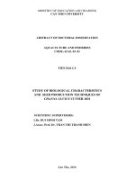
Maximum
MB
adsorption
capacity
qm
of
Fe-t-
CMQTBC(TTL) and Fe-b-CMQTBC(TTL) is higher than that of
CMQTBC(TTL) because it is affected by the same factors as with
CMQTBC(TTL) and affected by the complexing ability of iron with
MB (Figure 3.46) and MB oxidation ability of active iron sites.
Maximum MB adsorption capacity qm of Fe-b-CMQTBC(TTL) is
higher than that of Fe-b-CMQTBC(TTL) because The iron in the Feb-CMQTBC(TTL) is better dispersed, contains low valence iron sites
so it has the ability to oxidize MB and contain more π-π bonds.
20
Table 3.18, 3.19. Kinetic parameters for pseudo-fisrt-order and pseudo-second-order kinetic equations of of
adsorption process on Fe-t-CMQTBC(TTL) and Fe-b-CMQTBC(TTL)
Co
(mg/L)
R12
k1 (1/
q1e, cal
qe, exp
min)
(mg/g)
(mg/g)
R22
k2(g/(mg.
q2e,cal
v0
min))
(mg/g)
(mg/(g. min))
Fe-t-CMQTBC(TTL)
150
0,7491
0,1809
74,26
475,95
0,9997
0,0049
476,19
1111
200
0,7864
0,1447
37,32
546,95
0,9999
0,0108
555,56
3333
300
0,9303
0,1889
53,01
615,17
1
0,0085
625,00
3320
Fe-b-CMQTBC(TTL)
2
150
0,9694
0,0144
3,66
498,38
1
0,0200
500
5000
200
0,9614
0,0096
7,04
663,67
1
0,0075
666,67
3333
300
0,9150
0,0084
16,48
989,30
1
0,0050
1000
5000
2
R1 , R2 , k1, k2, q1e,cal, q2e,cal are correlation coefficient, the rate constant, adsorption capacity calculated
according to pseudo-first-order and pseudo-second-order kinetic equations, respectively; v0: start adsorption
rate.
.
21
Figure 3.46. MB adsorption
mechanism
on
carbon
mesoporous (MC) adsorbent
3.4.2. Study adsorption kinetics
Table 3.18, 3.19 show that the pseudo-second-order kinetic
equation
is fitted to the adsorption process MB on Fe-t-
CMQTBC(TTL), Fe-b-CMQTBC(TTL).
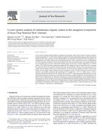
3.5. Evaluate the regeneration capacity of mesoporous carbon
Figure 3.54. MB adsorption performance on materials:
a) CMQTBC(TTL), b) Fe-t- CMQTBC(TTL)
and c) Fe-b-CMQTBC(TTL)
Adsorption efficiency after reuse of CMQTBC(TTL)
decreased significantly from 95.01% to 74.34% after 2 times of use.
For Fe-t-CMQTBC(TTL) over four times of reuse, MB
adsorption efficiency slightly decreased to 96.31%, 94.23%, 93.86%
and 83.90%, respectively.
For Fe-b-CMQTBC(TTL), it can be seen that after four
times of reuse, adsorption efficiency has not decreased by almost
99.47%. This can be explained by the fact that the iron nano-oxide is
highly dispersed on the surface of the material, increasing the
22
degradation process of the adsorbed MB, quickly releasing the
adsorption sites for reuse.
Hình 3.55, 3.56. XRD pattern (A) và TEM image (B) of Feb-CMQTBC(TTL) after 4 times of reuse
Figures 3.55 and 3.56 show that the state of iron oxide and
material structure is not significantly changed after 4 times of reuse.
3.6. Initial assessment of the catalytic ability of iron containing
mesoporous carbon
Figure 3.57, 3.58. Kinetic line when giving 0.03 g of material
Fe-t-CMQTBC(TTL) (a), Fe-b-CMQTBC(TTL) (b) in 100 ml MB
solution 300 mg/L at temperature 250C
The ability to remove MB of Fe-t-CMQTBC(TTL) and Fe-bCMQTBC(TTL) two materials with H2O2 is better than without
H2O2, proves that iron is the catalytic activity for MB decomposition
process. In particular, Fe-b-CMQTBC(TTL) showed the highest
activity, when H2O2 was present, MB concentration decreased
rapidly and almost zero after 40 minutes (Figure 3.58). Rapid
decomposition capacity MB is due to Fe-b-CMQTBC (TTL)
containing Fe2+ catalytic sites (XPS spectrum) accelerating MB
oxidation when H2O2 is present.
23
Conclusion
1. Carbon mesoporous were successfully synthesized by two
methods:
- Soft-templating method: Using soft-template F127, suitable
synthesis conditions: 100 oC, pH = 2. The obtained material has a
mesoporous structure with low order, the pore size of 5.4 nm, BET
surface area of 1693 m2/g.
- Hard-templating method: Using two hard-templates: SBA15 and MCF. Using the SBA-15, obtained materials have smaller
pore size (4.2 nm) and higher thermal stability (595 oC) than that of
using MCF (5.6 nm and 552 oC). When using SBA-15, suitable
amount of carbon precusor (sucrose) for impregnation is 2 times and
1 g of sucrose for each time.
2. Finding the new technique to synthesize CMQTB
materials by hard mold method is to fill liquid glass into the pore of
SBA-15 template before impregnating carbon source to limit the
penetration of carbon to seal the pore system of SBA-15, increased
the pore size of the material from 4.2 nm (without liquid glass) to
10.4 nm (with liquid glass). In addition, retaining a part of silicon in
the material increased the stability of the CMQTB materials (thermal
stability at 605oC) is a new idea in the field of synthesizing
mesoporous carbon materials.
3.
Iron
containing
CMQTBC(TTL)
materials
were
synthesized by two methods: impregnation and atom-planting. With
the impregnation method, iron exists in the form of amorphous iron
oxide. The atom-planting method is better than the impregnation
method: iron exists in the form of highly dispersed Fe2O3 and FeO
iron oxide, pore structure and pore size are almost unchanged.