Dynamics of multispeed transmissions for electric vehicles modelling analysis and validation
Bạn đang xem bản rút gọn của tài liệu. Xem và tải ngay bản đầy đủ của tài liệu tại đây (6.17 MB, 128 trang )
Dynamics of Multi-speed Transmissions for
Electric Vehicles: Modelling, Analysis and
Validation
Yuhanes Dedy Setiawan Liauw
Department of Mechanical Engineering
McGill University
Montreal, Canada
May 2018
A thesis submitted to McGill University in partial fulfillment of
the requirements for the degree of Doctor of Philosophy.
© 2018 Yuhanes Dedy Setiawan Liauw
2018/05/15
i
Abstract
Electric vehicles (EVs) are growing in importance. One promising technique to improve the
performance and efficiency of EVs is the introduction of multi-speed transmissions (MSTs).
Multiple speed ratios can maintain the traction motor at the most efficient operation region,
especially for medium- and heavy-duty EVs. In order to support the optimum design and
control of MSTs for EVs, a thorough dynamics analysis is needed. However, a complete
mathematical model of MSTs for EVs has not yet been developed. This model is needed
to analyze and optimize the gear-shifting events such that a swift, seamless shifting can be
achieved. This task is currently conducted by means of simplified dynamics models. The
work reported here includes the formulation of a detailed model of a novel modular MST
for EVs that takes into account discontinuities brought about by backlash and dry friction
in the gear pairs. The dynamic response of gear-shifting was simulated for validation, the
results were verified experimentally on an in-house developed testbed of the novel MST.
In addition, multi-speed transmissions undergo topology changes during gear-shifting.
Nevertheless, this important phenomenon has been overlooked in transmission-model formulation, which results in an inaccurate prediction of the dynamic response. To fill this
gap, a topology-change model was formulated to address the topology change in vehicle
transmissions during gear-shifting. The velocity jump brought about by topology changes
is given due attention. A case study is included, whereby the model is implemented in a
novel modular MST for EVs. Both simulation and experimental tests were conducted for
validation. A good agreement between simulation and experimental results was achieved,
which verifies the pertinence of the model. It was concluded that the topology-change model
improves the capability of transmission mathematical models in predicting the transmission
dynamic response during gear-shifting.
Furthermore, the transmission model was used in a range-prediction model of EVs with
MSTs. Most range models are solely available for EVs with fixed gearing. Moreover, transmissions are assessed solely with a constant efficiency in EV range-prediction procedures
available in the literature. A simple and accurate range model for EVs with MSTs is
proposed in this dissertation. In order to predict the range of EVs with MSTs reliably,
the actual transmission efficiency was computed by means of a transmission model. A
case study aimed at predicting the range of the GM EV1 with a two-speed novel modular
transmission is included. Moreover, a simulation test with constant transmission efficiency,
ii
intended to underline the advantages brought about by the actual transmission efficiency
in range-prediction, is provided. The results indicate that the range of the two-speed GM
EV1 simulated with constant transmission efficiency is 7.73% longer than the range of the
standard GM EV1. Nevertheless, this number could actually reach up to 13.09% when
the range is predicted with the actual efficiency. This result was verified by means of the
detailed model created in this dissertation that estimated a 12.76% of range improvement.
In summary, this thesis highlights the advantages of realistic models that lead to a reliable
prediction of the transmission efficiency and the range of EVs with MSTs.
iii
R´
esum´
e
´ sont de plus en plus r´epandus. Une avenue prometteuse pour
Les v´ehicules ´electriques (VE)
´ est l’utilisation des transmissions multi
am´eliorer les performances et l’efficacit´e des VE
vitesses (TMV). Des rapports de vitesse multiples permettent de maintenir le moteur de
traction dans sa zone de fonctionnement le plus efficace, en particulier pour les v´ehicules
´electriques de moyenne et de grande puissance. Pour arriver `a une conception et une
´ une analyse dynamique approfondie est
commande optimales des TMV destin´ees `a des VE,
´ n’a pas `a ce
n´ecessaire. Cependant, un mod`ele math´ematique complet des TMV pour VE
jour encore ´et´e ´elabor´e. Ce mod`ele est n´ecessaire pour analyser et optimiser les changements
de vitesse de sorte qu’un changement rapide et continu puisse s’effectuer. Cette tˆache est
actuellement men´ee `a l’aide de mod`eles dynamiques simplifi´es. Le travail pr´esent´e ici aborde
la formulation d’un nouveau mod`ele pour les TMV qui prend en compte les discontinuit´es
provoqu´ees par des jeux et le frottement sec au niveau des pairs d’engrenages. La r´eponse
dynamique du changement de vitesse a ´et´e simul´ee pour ˆetre valid´ee, les r´esultats ont ´et´e
v´erifi´es exp´erimentalement sur un banc d’essai maison de la nouvelle TMV.
De plus, les transmissions multi vitesses subissent un changement de topologie lors
des changements de vitesse. Toutefois, cet important ph´enom`ene a ´et´e n´eglig´e dans les
formulations des mod`eles de transmission, se soldant en une pr´ediction inexacte de la
r´eponse dynamique. Pour r´epondre `a cette probl´ematique, un mod`ele des changements de
topologie a ´et´e con¸cu pour pr´evoir ces derniers `a l’int´erieur de la transmission des v´ehicules
lors des changements de vitesse. Le saut de vitesse caus´e par ces changements a donc re¸cu
ainsi l’attention n´ecessaire. Une ´etude de cas est incluse, o`
u le mod`ele est impl´ement´e sur
´ Des simulations ainsi que des tests exp´erimentaux
une nouvelle TMV modulaire pour VE.
ont ´et´e men´es pour validation. Une bonne concordance entre les r´esultats exp´erimentaux et
de simulations a ´et´e observ´ee, ce qui confirme la pertinence du mod`ele. Il a ´et´e conclu que
le mod`ele de changements de topologie am´eliore la capacit´e des mod`eles math´ematiques de
transmission de pr´evoir la r´eponse dynamique de cette derni`ere durant les changements de
vitesse.
Finalement, le mod`ele de transmission est utilis´e pour pr´edire les distances pouvant ˆetre
´ munis de TMV. Les mod`eles actuels n’existent que pour les v´ehicules
parcourues par les VE
`a engrenages fixes. De plus, au travers de la litt´erature disponible, ces transmissions sont
´evalu´ees en consid´erant seulement un rendement constant en ce qui concerne la pr´ediction
iv
´ munis
de distances. Un mod`ele simple et pr´ecis pouvant servir `a cette fin pour les VE
d’une TMV est propos´e dans cette dissertation. Pour pouvoir pr´edire avec fiabilit´e la
distance pouvant ˆetre parcourue, c’est-`a-dire l’autonomie, le rendement r´eel est calcul´e `a
l’aide d’un mod`ele de la transmission. Une ´etude de cas portant sur l’autonomie de la
GM EV1 avec une nouvelle transmission modulaire `a deux vitesses est incluse. De plus,
une simulation avec un rendement de transmission constant, effectu´ee pour souligner les
avantages de prendre en compte le rendement r´eel dans la pr´ediction d’autonomie, est
´egalement fournie. Les tests permettent de conclure que l’autonomie de la GM EV1 `a deux
vitesses pr´edite avec un rendement constant est 7,73 % plus ´elev´ee que celle de la GM
EV1 standard. Cependant, ce nombre pourrait dans les faits atteindre 13,09 % lorsque la
distance atteignable est pr´edite avec le rendement r´eel. Ce r´esultat a ´et´e v´erifi´e `a l’aide
d’un mod`ele d´etaill´e cr´e´e pour cette th`ese qui estime que l’am´elioration de l’autonomie
est de l’ordre de 12,76 %. Bref, cette th`ese met en lumi`ere les avantages de mod`eles plus
´ munis de
r´ealistes qui permettent de mieux pr´edire le rendement et l’autonomie des VE
TMV.
v
Acknowledgments
I would like to express my most sincere gratitude to all those who helped me during my
study and meaningful life in Canada. First of all, I would like to give my highest praise to
God for all the help and guidance that I have received, to allow me to finish all my research
and thesis in the PhD program.
Second, I would like to express my deepest gratitude to my supervisor, Professor Jorge
Angeles, who has helped me significantly in completing my PhD program. I really appreciate the kindness and support that he provided to me during my study in his excellent
laboratory.
I would also like to express my sincere gratitude to the members of my thesis committee,
Professors Jozsef K¨ovecses and Arun Misra, for their helpful comments and suggestions
throughout my work.
Furthermore, I would like to express my profound gratitude to Mehdi Roozegar, Dr.
Ting Zou and Dr. Alexei Morozov for their great help and advice that allowed me to finish
my research project and my PhD thesis.
Last but not least, I would like to express my deepest gratitude to my father, Joeng Ji
Liauw, my mother, Erlani Go, my sister, Ciska Yuni Setiawan Liauw and all my relatives
for their love, endless prayers, encouragement and support for me not only in completing
the PhD program but also in the whole of my life.
vi
vii
Contents
1 Introduction
1.1 Background . . . . . . . . . . . . . . . . . . . . . . . . . . . . . .
1.2 Multi-speed Transmissions for Electric Vehicles . . . . . . . . . .
1.3 Mathematical Models for Multi-speed Transmissions . . . . . . . .
1.4 Topology Changes in Multi-speed Transmissions . . . . . . . . . .
1.5 Range Model of Electric Vehicles with Multi-speed Transmissions
1.6 Research Plan: Description and Objectives . . . . . . . . . . . . .
1.7 Claims of Originality . . . . . . . . . . . . . . . . . . . . . . . . .
1.8 Thesis Organization . . . . . . . . . . . . . . . . . . . . . . . . . .
.
.
.
.
.
.
.
.
.
.
.
.
.
.
.
.
.
.
.
.
.
.
.
.
.
.
.
.
.
.
.
.
.
.
.
.
.
.
.
.
.
.
.
.
1
1
4
13
14
16
17
18
18
2 A Novel Modular Multi-speed Transmission
21
2.1 Design Principles . . . . . . . . . . . . . . . . . . . . . . . . . . . . . . . . . 21
2.1.1 The Underdrive Gear Train . . . . . . . . . . . . . . . . . . . . . .
28
2.2 Testbed Set-up . . . . . . . . . . . . . . . . . . . . . . . . . . . . . . . . .
32
3 Formulation of the Mathematical Model
3.1 A Multi-speed Transmission . . . . . . . . . .
3.2 Linear Complementarity Problem Formulation
3.3 Backlash Modelling . . . . . . . . . . . . . . .
3.4 Friction Modelling . . . . . . . . . . . . . . .
3.5 Model Parameterization . . . . . . . . . . . .
3.6 Modal Analysis . . . . . . . . . . . . . . . . .
3.7 Simplified Model . . . . . . . . . . . . . . . .
.
.
.
.
.
.
.
.
.
.
.
.
.
.
.
.
.
.
.
.
.
.
.
.
.
.
.
.
.
.
.
.
.
.
.
.
.
.
.
.
.
.
.
.
.
.
.
.
.
.
.
.
.
.
.
.
.
.
.
.
.
.
.
.
.
.
.
.
.
.
.
.
.
.
.
.
.
.
.
.
.
.
.
.
.
.
.
.
.
.
.
.
.
.
.
.
.
.
.
.
.
.
.
.
.
.
.
.
.
.
.
.
.
.
.
.
37
38
47
50
51
52
54
54
viii
Contents
4 Gear-shifting Analysis
57
4.1 Simulation . . . . . . . . . . . . . . . . . . . . . . . . . . . . . . . . . . . . . 57
4.1.1 Gear-shifting Mechanism . . . . . . . . . . . . . . . . . . . . . . . . . 57
4.2 Experimental Validation . . . . . . . . . . . . . . . . . . . . . . . . . . . .
62
5 A Topology-change Model
5.1 Model Formulation . . . . . . . . .
5.2 Case Study . . . . . . . . . . . . .
5.3 Experimental Work and Simulation
5.3.1 Velocity-jump Calculation .
5.4 Model Implementation . . . . . . .
.
.
.
.
.
.
.
.
.
.
.
.
.
.
.
.
.
.
.
.
.
.
.
.
.
.
.
.
.
.
.
.
.
.
.
.
.
.
.
.
.
.
.
.
.
.
.
.
.
.
.
.
.
.
.
.
.
.
.
.
.
.
.
.
.
.
.
.
.
.
.
.
.
.
.
.
.
.
.
.
.
.
.
.
.
.
.
.
.
.
.
.
.
.
.
6 Range Model of Electric Vehicles with Multi-speed Transmissions
6.1 Range Model Formulation . . . . . . . . . . . . . . . . . . . . . . . .
6.2 Case Study: An Electric Vehicle with a Two-speed Transmission . . .
6.3 Gear-shifting Schedule . . . . . . . . . . . . . . . . . . . . . . . . . .
6.3.1 Range Simulation . . . . . . . . . . . . . . . . . . . . . . . . .
6.4 Transmission Efficiency . . . . . . . . . . . . . . . . . . . . . . . . . .
6.5 Range Simulation with the Actual Transmission Efficiency . . . . . .
.
.
.
.
.
.
.
.
.
.
.
.
.
.
.
65
65
68
69
70
. 74
79
. . .
79
. . .
83
. . . . 84
. . .
85
. . .
86
. . .
88
7 Conclusions and Recommendations for Further Research
91
7.1 Conclusions . . . . . . . . . . . . . . . . . . . . . . . . . . . . . . . . . . . . 91
7.2 Recommendations for Future Research . . . . . . . . . . . . . . . . . . . .
92
A Simulation Parameters
95
ix
List of Figures
1.1
1.2
1.3
1.4
1.5
1.6
1.7
1.8
1.9
1.10
Public electric bus in Montreal, Canada [10] . . . . . . . . . . . . . .
Tesla Semi truck [12] . . . . . . . . . . . . . . . . . . . . . . . . . . .
Pure EV configuration [23] . . . . . . . . . . . . . . . . . . . . . . . .
MHEV powertrain (FG = fixed gearing, M = motor, D = differential)
Typical electric motor characteristics [25] . . . . . . . . . . . . . . . .
Tractive effort: single-speed vs two-speed EVs [26] . . . . . . . . . . .
Efficiency maps: 1-speed vs 2-speed [27] . . . . . . . . . . . . . . . .
A seamless two-speed transmission for EVs [40] . . . . . . . . . . . .
Two-speed dual-clutch transmission for EVs [7] . . . . . . . . . . . .
A two-speed dual-brake transmission for EVs [45] . . . . . . . . . . .
. . .
2
. . .
3
. . .
5
[24]
5
. . .
6
. . . . 7
. . .
8
. . . . 11
. . .
12
. . .
13
2.1
2.2
2.3
2.4
2.5
2.6
2.7
2.8
2.9
2.10
2.11
2.12
2.13
2.14
(a) A simple PGS; (b) a diagram of the MST . . . . . . . . . . . . .
Transmission modules: (a) underdrive, (b) overdrive . . . . . . . . . .
The novel modular MST concept . . . . . . . . . . . . . . . . . . . .
The novel modular MST . . . . . . . . . . . . . . . . . . . . . . . . .
The iconic model of the novel modular MST, with all clutches open .
Functional representation of the novel modular MST . . . . . . . . .
Graph representation of the transmission when all clutches are open .
The first operation mode: (a) functional and (b) graph representation
Functional representation of the underdrive gear train . . . . . . . . .
Lever analogy of the underdrive gear train . . . . . . . . . . . . . . .
Speed analysis with the simplified lever analogy . . . . . . . . . . . .
In-house developed testbed of the novel modular MST . . . . . . . .
Multi-disk clutch . . . . . . . . . . . . . . . . . . . . . . . . . . . . .
Multi-disk clutch diagram [114] . . . . . . . . . . . . . . . . . . . . .
.
.
.
.
.
.
.
.
.
.
.
.
.
.
.
.
.
.
.
.
.
.
.
.
.
.
.
.
.
.
.
.
.
.
.
.
.
.
.
.
.
.
.
.
.
.
22
23
24
26
27
27
28
29
29
30
31
32
33
33
x
List of Figures
2.15
2.16
2.17
2.18
Ring clutch . . . . . . . . . .
Control system diagram of the
Testing site . . . . . . . . . .
Electronic box . . . . . . . . .
.
.
.
.
. . 34
.
35
.
36
.
36
3.1
3.2
3.3
3.4
The iconic model of the novel modular MST . . . . . . . . . . . . . . . .
Representation of vector q and its associated matrices (M, C or K) . .
(a) a simple gear pair, (b) backlash in the gear teeth, (c) backlash model
Friction-torque characteristics . . . . . . . . . . . . . . . . . . . . . . . .
.
39
.
46
. . 51
.
52
4.1
4.2
4.3
4.4
4.5
4.6
4.7
4.8
4.9
The iconic model of the underdrive gear train of the novel modular MST
Simulink file of the comprehensive model . . . . . . . . . . . . . . . . . .
Simulink file of the simplified model . . . . . . . . . . . . . . . . . . . . .
Control system block diagram to simulate the comprehensive model . . .
Control system block diagram to simulate the simplified model . . . . . .
Gear-shifting algorithm in simulation phase 1 . . . . . . . . . . . . . . .
Experimental verification of the models . . . . . . . . . . . . . . . . . . .
Comparison of the angular velocities of the planet gears . . . . . . . . . .
Comparison of the angular velocities of the ring gears . . . . . . . . . . .
.
.
.
.
.
.
.
.
. .
5.1
5.2
5.3
5.4
5.5
5.6
5.7
5.8
5.9
Functional representation of the underdrive gear train
Flow chart of simulation phase 1 . . . . . . . . . . . .
Simulation phase 1 results . . . . . . . . . . . . . . .
(a) Clutch torque capacity, (b) speed ratio . . . . . .
(a) The applied torques f , (b) τ . . . . . . . . . . . .
Flow chart of simulation phase 2 . . . . . . . . . . . .
Gear-shifting algorithm . . . . . . . . . . . . . . . . .
Simulation phase 2 results . . . . . . . . . . . . . . .
Angular velocities of (a) planet gears, (b) ring gears .
of the modular MST
69
. . . . . . . . . . . .
69
. . . . . . . . . . . .
72
. . . . . . . . . . . .
72
. . . . . . . . . . . .
73
. . . . . . . . . . . . . 74
. . . . . . . . . . . .
75
. . . . . . . . . . . .
76
. . . . . . . . . . . .
76
6.1
6.2
6.3
6.4
6.5
EV range modelling
GM EV1 [132] . . .
SFUDS [13] . . . .
Gear-shift schedule
Gear-shift time . .
.
.
.
.
.
[13]
. . .
. . .
. . .
. . .
.
.
.
.
.
.
.
.
.
.
.
.
.
.
.
. . . . . . . . . . . . . . . .
novel modular MST testbed
. . . . . . . . . . . . . . . .
. . . . . . . . . . . . . . . .
.
.
.
.
.
.
.
.
.
.
.
.
.
.
.
.
.
.
.
.
.
.
.
.
.
.
.
.
.
.
.
.
.
.
.
.
.
.
.
.
.
.
.
.
.
.
.
.
.
.
.
.
.
.
.
.
.
.
.
.
.
.
.
.
.
.
.
.
.
.
.
.
.
.
.
.
.
.
.
.
.
.
.
.
.
.
.
.
.
.
.
.
.
.
.
.
.
.
.
.
.
.
.
.
.
.
.
.
.
.
.
.
.
.
.
.
.
.
.
.
.
.
.
.
.
.
.
.
.
.
.
.
.
.
.
.
.
.
.
.
.
.
.
58
58
59
59
60
60
63
63
64
.
80
.
83
. . 84
.
85
.
86
List of Figures
6.6
6.7
xi
Transmission angular velocities and torques . . . . . . . . . . . . . . . . . . 87
Transmission efficiency of a two-speed novel modular transmission for SFUDS 88
xii
xiii
List of Tables
1.1
1.2
Performance comparison between Tesla Semi and a comparable diesel truck
Specific energies of common batteries and fossil fuels [22] . . . . . . . . . . .
2.1
2.2
2.3
Clutch state configuration of the novel modular MST (× denotes closed) . . 27
Clutch state configuration of the underdrive gear train (× denotes closed) .
30
Testbed servo motor specification . . . . . . . . . . . . . . . . . . . . . . .
32
3.1
Coefficient definition . . . . . . . . . . . . . . . . . . . . . . . . . . . . . .
56
4.1
Tuned PID gains . . . . . . . . . . . . . . . . . . . . . . . . . . . . . . . .
60
6.1
6.2
GM EV1 parameters [13] . . . . . . . . . . . . . . . . . . . . . . . . . . . . . 84
Single- vs two-speed GM EV1 range comparison . . . . . . . . . . . . . . .
89
A.1 Parameter definition . . . . . . . . . . . . . . . . . . . . . . . . . . . . . .
A.2 Simulation parameter values . . . . . . . . . . . . . . . . . . . . . . . . . .
3
4
95
96
xiv
xv
List of Acronyms
AMT
CVT
DAE
DCT
EV
FFV
FUDS
ICEV
MHEV
MST
NEDC
PCC
PGS
PGT
SFUDS
Automatic Manual Transmission
Continuously Variable Transmission
Differential Algebraic Equation
Dual-clutch Transmission
Electric Vehicle
Fossil-fuel Vehicle
Federal Urban Driving Schedule
Internal Combustion Engine Vehicle
Medium- and Heavy-duty Electric Vehicle
Multi-speed Transmission
New European Driving Cycle
Planet-carrier Clutch
Planetary Gear Set
Planetary Gear Train
Simplified Federal Urban Driving Schedule
xvi
1
Chapter 1
Introduction
1.1 Background
Electric vehicles (EVs) appear as the best alternatives to fossil-fuel vehicles (FFVs) [1, 2].
The former beat the latter over a broad spectrum of issues, from environmental concerns,
such as global warming and fuel-price increase, to personal mobility within short distances.
Moreover, stricter regulations on emissions are currently being enforced, which makes zeroemission EVs the ideal solution [3]. Electric-vehicle ranges have also become reasonable
among consumers due to major advancements in battery and charging-device technologies.
As a consequence, EVs have grown rapidly in the last decade.
The significant growth of EVs in the market stems from numerous advantages of EVs
over FFVs or internal-combustion-engine vehicles (ICEVs). First and foremost, EVs do not
depend on non-renewable sources of energy as ICEVs do. Second, EVs are more efficient
than their counterparts [4]. Electric vehicles are propelled by highly efficient electric motors and consume minimum amounts of energy during idling periods, as in the presence of
traffic jams. In addition, EVs benefit from a regenerative braking feature that transforms
the motor into a generator that decelerates the vehicle and recharges the battery simultaneously [5]. Third, an EV configuration is simpler, hence easier and more economical
to maintain [6]. Last, EVs are more user-friendly than ICEVs regarding pollution and
noise [7–9].
As a result of the advantages above, the concept of EV has broadened to mediumand heavy-duty electric vehicles (MHEVs), such as buses and trucks. In fact, larger energy
savings can be gained from these types of vehicles because they carry higher loads and travel
2
Introduction
Fig. 1.1: Public electric bus in Montreal, Canada [10]
longer distances. Consequently, MHEVs have been implemented for public transportation
in major cities, such as Montreal, Canada, as depicted in Fig. 1.1. Three electric buses are
currently running in the city of Montreal, the size of the fleet gradually increasing to achieve
the Montreal transportation goal of purchasing solely fully electric buses by 2024 [11]. It
goes without saying that the transportation industry is heading towards replacing fossil-fuel
buses with MHEVs.
Another type of MHEVs that plays an important role in transportation is electric trucks.
Trucks in general have been utilized widely for short- and long-haul delivery. Unlike their
bus counterparts, trucks carry heavier loads and travel longer distances. As a consequence,
electrification and hybridization have been attractive options due to the high energy consumption and gas emission in trucks. Moreover, electrification of trucks promotes significant
advantages in terms of energy and time, which translate into cost reduction. A substantial
number of electric trucks has been operating under tens of thousands of pounds of goods
for hundreds of miles. More than eight companies all over the world currently manufacture MHEVs. Furthermore, Tesla, one of the pioneers in EVs, unveiled a new heavy-duty
electric truck Semi in November 2017, as captured in Fig. 1.2.
Semi is foreseen to outperform diesel trucks to a great extent. For starter, Semi is
reportedly 20% more cost-effective than diesel trucks. Table 1.1 lists the performance
prediction of Semi in comparison to a diesel truck, under similar conditions, that Tesla
1.1 Background
3
Fig. 1.2: Tesla Semi truck [12]
Table 1.1: Performance comparison between Tesla Semi and a comparable diesel truck
Performance
Acceleration 0–60 mph (without a trailer)
Acceleration 0–60 mph (with 80,000 lb load)
Top speed at 5% grade (maximum gross)
Tesla Semi
5s
20 s
65 mph
Diesel truck
15 s
60 s
45 mph
CEO, Elon Musk, highlighted in the Semi introduction event. The major advantage of
electric motors over internal combustion engines in terms of performance is that the former
are able to exploit the maximum torque from the beginning. Thus, this brings about
significant benefits on the acceleration performance of Semi in comparison to a comparable
diesel truck. Moreover, Semi is aerodynamically designed with a drag coefficient as low as
that of a sports car, hence more energy-saving. The production is expected to debut in
2019, which signifies the importance of MHEVs in the transportation industry.
To accommodate the long-term growth of MHEVs, or EVs in general, sizeable R&D
investment has been announced. In fact, R&D of EVs commenced since EVs were first
commercialized by the end of the 19th century [13]. The main purpose of the R&D work
in this context was to replace fossil-fuel engines with electric motors, in order to reduce
greenhouse-gas emissions and improve efficiency [14]. Consequently, extensive investigation
to improve the efficiency in EVs have been conducted [14–21]. Nevertheless, an inevitable
concern is still present when replacing fossil-fuel vehicles with EVs, namely, range phobia or anxiety of the range that EVs can travel. Table 1.2 compares the specific energies
4
Introduction
Table 1.2: Specific energies of common batteries and fossil fuels [22]
Energy Storage Type
Battery
Battery
Battery
Fossil Fuel
Fossil Fuel
Sub-type
Lead/Acid
NiMH
Li-ion
Gasoline
Diesel
Specific Energy (Wh/kg)
35–50
70–95
80–130
11,800
11,950
of common batteries and fossil fuels. Apparently, the range that EVs can reach before
a need to recharge is still limited. In addition, EVs are not as convenient as fossil-fuel
vehicles because charging stations are not yet as widely distributed as gas stations. Therefore, contemporary R&D in EVs primarily aims to improve the energy efficiencies without
compromising the performance. One promising approach is to implement a multi-speed
transmission (MST).
The research work in this dissertation is concerned with the dynamics of multi-speed
transmissions in medium- and heavy-duty electric vehicles, such as trucks and buses. Three
primary tasks were carried out, namely, the formulation of a comprehensive model of MSTs
for EVs, analysis of the topology changes of MSTs upon gear-shifting, and the rangeprediction of EVs with MSTs. In the following sections, the application of MSTs to EVs
is explained. After this, the transmission mathematical-modelling scene is surveyed. Next,
the topology changes of MSTs upon gear-shifting are studied. Lastly, the description of
the range-prediction of EVs with MSTs follows.
1.2 Multi-speed Transmissions for Electric Vehicles
The configuration of pure EVs is depicted in Fig. 1.3, where the thin and thick arrows account for the signal and power flows, respectively. Unlike the configuration of ICEVs, most
mechanical components are replaced with electronics, which incidentally leads to lower energy losses. The driver inputs on the accelerator and brake are delivered electronically to
the controller, with significant gains in higher precision. Energy and auxiliary systems manage the energy and auxiliary components in the vehicles. In addition, the inputs from the
driver can be manipulated by the controller to achieve a more efficient operation. A power
converter is needed for the controller to send signals to the motor because of different voltage operation. Subsequently, the motor operates according to the signal from the controller.
1.2 Multi-speed Transmissions for Electric Vehicles
5
Fig. 1.3: Pure EV configuration [23]
(a)
(b)
Fig. 1.4: MHEV powertrain (FG = fixed gearing, M = motor, D = differential) [24]
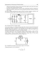
Mechanical transmissions may include fixed gearing or multi-speed transmissions.
Two main MHEV powertrain configurations are displayed in Fig. 1.4. Some MHEVs
adopt single-speed transmission or fixed gearing, as electric motors are believed to be sufficient in providing all required power. The powertrain configuration for this type of MHEVs
is illustrated in Fig. 1.4(a). Each wheel has a motor equipped with a fixed gearing. In comparison, another group of MHEVs has one primary motor that provides the torque for the
whole vehicle instead of smaller motors in each wheel, as indicated in Fig. 1.4(b). The
concept is similar to the ICEVs, with a differential to distribute the power to the wheels.
Either fixed gearing or a multi-speed transmission is utilized between the motor and differ-
6
Introduction
Fig. 1.5: Typical electric motor characteristics [25]
ential to manipulate the energy. In the case of MHEVs with a multi-speed transmission,
the energy flow can be better managed in the presence of a number of gear ratios.
Without a multi-speed transmission, MHEVs must be equipped with cumbersome electric motors to compensate their heavy loads, which is not feasible economically. Application of MSTs can come to the rescue by downsizing the motors and their accessories.
Several companies, such as EMOSS, Electric Vehicle International and Balqon, have produced MHEVs with a multi-speed transmission. On the contrary, other companies, such
as Hytruck, Motiv Power Systems, and Smith Electric Vehicles, have dispensed with multispeed transmissions in their MHEVs on the basis that electric motors have a wide range
of operation, as required by MHEVs, thereby obviating multi-speed transmissions. This
is, therefore, still a controversial issue because it is unclear whether the application of
multi-speed transmissions in MHEVs, or EVs in general, is necessary at all [24].
The performance improvement of EVs by application of MSTs can be investigated by
examining the effects of the MST application on the efficiency maps of the EV motors. A
1.2 Multi-speed Transmissions for Electric Vehicles
7
Fig. 1.6: Tractive effort: single-speed vs two-speed EVs [26]
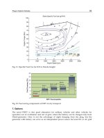
typical efficiency map of EV is given in Fig. 1.5. A straight line on the high torque that
declines at a speed of around 1,500 rpm to the right vertical axis is the power envelope
that indicates the limit at which the motor can operate. Moreover, the efficiency levels of
the motor are represented by isocontours, with the numbers indicating efficiency level of
that particular torque-speed state. As revealed in the figure, 90% is the highest efficiency
region, located in the medium torque and lower medium speed. In other words, in order to
drive efficiently, the vehicle cannot travel with a high speed, which is not convenient.
By means of the application of MSTs, the vehicle performance can be manipulated
to drive efficiently with relatively higher speed, as justified in Fig. 1.6 that compares the
tractive efforts between a standard (single-speed) EV and a comparable EV with a twospeed transmission. When the two-speed vehicle operates in the first gear, the attainable
torque is amplified by the gear ratio, as indicated in the figure. This is advantageous for
MHEVs because a high torque is required at the start-up. Furthermore, the second gear
of the transmission allows a vehicle to travel at a higher speed, which enables the vehicles
to reach the destination sooner than its single-speed counterparts. Equally important, the
application of MSTs permits the vehicle to take advantage of the above benefits while
maintaining the operation in the high-efficiency region. More specifically, the application
of MSTs adjusts the efficiency region of the motor in accordance with the MST gear ratios.
Figure 1.7 exemplifies the efficiency map adjustment due to the application of MSTs
to EVs. The top figure displays the efficiency map of EVs with a single-speed. The