A 2D model for analysis of rain wind induced vibration of stay cables
Bạn đang xem bản rút gọn của tài liệu. Xem và tải ngay bản đầy đủ của tài liệu tại đây (3.66 MB, 15 trang )
Journal of Science and Technology in Civil Engineering NUCE 2019. 13 (2): 33–47
A 2D MODEL FOR ANALYSIS OF RAIN-WIND INDUCED
VIBRATION OF STAY CABLES
Truong Viet Hunga,∗, Vu Quang Vietb
a
Faculty of Civil Engineering, Thuyloi University, 175 Tay Son street, Dong Da district, Hanoi, Vietnam
b
Faculty of Civil Engineering, Vietnam Maritime University, 484 Lach Tray street,
Le Chan district, Hai Phong, Vietnam
Article history:
Received 19/03/2019, Revised 09/04/2019, Accepted 25/04/2019
Abstract
Rain-wind induced vibration of stay cables (RWIV) in cable-stayed bridges is a special aerodynamic phenomenon as it is easy to be influenced by many factors, especially velocity and impact angle of wind. This
paper proposes a new assumption of the impact angle of wind on the cable in analyzing cable vibration response subjected to wind and rain. This angle is considered as a harmonic oscillation function around the
equilibrium position that is the initial angle of impact, and its angular frequency equals of the rivulet and the
cable. The amplitude of impact angle of wind depends on wind velocity, initial position and that of rivulet. The
assumption is verified by comparison with experimental results. The effects of rivulet oscillation components
and aerodynamic forces are also discussed in this paper.
Keywords: stay cable; rain-wind induced vibration; rivulet; analytical model; vibration.
/>
c 2019 National University of Civil Engineering
1. Introduction
In last few decades, lots of long-span bridges have been built over the world. Together with the
rapid development of construction technologies and new materials, the main tendency of research and
development of bridge engineering is to concentrate on super long span and slimmer structures in the
21st century. However, the slimmer structures are, the more difficulties have to face, specially in the
dynamic, seismic, and aerodynamic engineering. Modern cable-stayed bridges, one of the long-span
bridges, are vulnerable to aerodynamics and wind-induced vibrations. Stay cables of these bridges
usually have low structural damping and a wide range of natural frequencies, so they are sensitive
to natural wind. Among various types of wind-induced vibrations of cables of cable-stayed bridges,
rain-wind induced vibration (RWIV) from firstly observed by Hikami and Shiraishi et al. [1] on the
Meikonishi bridge attracted the attention of scientists around the world.
Hikami and Shiraishi revealed that neither vortex-induced oscillations nor a wake galloping could
explain this phenomenon. The frequency of the observed vibrations was lower than the critical one of
the vortex-induced vibrations. However, it was not the wake Galloping because the cables were too
far apart to be able to affect each other. Bosdogianni and Olivari et al. [2] asserted that Rain–wind
induced vibration (RWIV) was a large amplitude and low frequency vibration of cables in cable-stayed
bridges under the effects of wind and rain. Series of laboratory experiments (Matsumoto et al. [3],
∗
Corresponding author. E-mail address: (Hung, T. V.)
33
Hung, T. V., Viet, V. Q. / Journal of Science and Technology in Civil Engineering
Flamand et al. [4], Gu and Du et al. [5], Gu et al. [6], etc.) and field later (Costa et al. [7], Ni et al.
[8], among others) were conducted. They found that the basic characteristic of RWIV is due to the
formation of the upper rivulet on cable surface which oscillates with lower modes in a certain range
of wind speed under a little or moderate rainfall condition. Teng Wu at el. [9] also pointed out the
vibration amplitude is related to the length, inclination direction, surface material of cable, and the
wind yaw angle.
In parallel with conducting the experiments, the theoretical models explaining this phenomenon
are also the focus of scientific research. Yamaguchi et al. [10] established the first theoretical model
with two-dimensional 2-DOF motion equations of cable. He found that when the fundamental frequency of upper rivulet oscillation coincided with the cable natural frequency, aerodynamic damping
was negative and caused the large amplitude oscillation of stayed cable. Thereafter, Xu et al. [11],
Wilde et al. [12] presented a SDOF model based on Yamaguchi’s theory, in which, the motion equation of rivulets was not established. The forces of cable caused by rivulet motion were substituted into
the cable motion equation considering them as known parameters based on the assumption of rivulets
motion law. With the other assumption of sinusoidal movement of rivulet, Gu et al. [6] developed an
analytical model for RWIV of three-dimensional continuous stayed cable with quasi-moving rivulet.
Besides, Limaitre et al. [13] based on the lubrication theory to simulate the formation of rivulets and
study the variation of water film around horizontal and static cable. Bi et al. [14] presented a 2D
coupled equations model of water film evolution and cable vibration based on the combination of
lubrication theory and vibration theory of single-mode system.
It can be seen that Yamaguchi’s theory was applied and further developed in lots of later studies.
SDOF model explains the mechanism of this oscillation as follows: rainwater formed on the surface of
cable of two rivulets, and they change the shape of the cross section of the cable and the aerodynamic
forces affecting the cable. While the lower rivulet is in stable equilibrium, the upper rivulet is unstable.
The presence of the upper rivulet alters the surface contact between the cable and wind, and wind
blowing through the cable will induce tangled winds causing oscillation of the cable. Maybe the
rivulet frequency equaling that of the cable is the reason to cause resonance phenomenon.
One of the limitations of Yamaguchi’s theory is that by only considering phenomena combining
wind and rain effects on low-frequency cables, Yamaguchi ignored the effect of fluctuation of rivulet
to the angle of the wind acting on cable. This leads to the damping ratio of the equation independent
with time (Xu et al. [11], Li et al. [15], Hua Li et al. [16], Zhan et al. [17]), or displacement of the
cable is zero when there is no appearance of rivulet on the cable (Wilde et al. [12]). In terms of value,
this calculation changes not too much the amplitude value of the cable but it does not appreciate the
role of the resistance force, which changes cable-damping ratio over time. Impact angle, drag and lift
coefficients are important components affecting the implementation of wind pressure on the cable.
To overcome the above disadvantages, in this paper, a new assumption about impact angle of wind
will be proposed. Wind angle effect on cable in RWIV is considered as a function harmonic oscillation
around the equilibrium position is the initial angle of impact (γ0 ), and its angular frequency equals that
of the rivulet and cable. Oscillation amplitude depends on the wind velocity (U0 ), amplitude (am ) and
initial position (θ0 ) of the rivulet. This oscillation is reviewed only by wind and rain combined effect,
thus, when there is the absence of rivulet harmonic motion wind angle effect is γ0 . The assumption
is verified by the comparison with experimental results. The effects of rivulet oscillation components
and aerodynamic forces are also discussed.
34
where e is an influence factor.
When
is selected
as 1, gof0 Science
is the angle
of attack forin Civil Engineering
Hung,
T. V.,eViet,
V. Q. / Journal
and Technology
the cylinder without rivulet, and when e is set zero it is the same as that on the cable
without
rivulet
yaw
angle.
The
effects
the mean
component
2.e Single
degree
of
freedom
model
e isof
where
isand
an influence
factor.
When
selected
as 1, wind
the angle
of attack foralong the
g 0 is speed
cylinder
axis
and
wind
turbulence
are
not
considered.
the cylinder without rivulet, and when e is set zero it is the same as that on the cable
Theand
stress-strain
Considering
a cable
withcomponent
velocityalong
of wind
without rivulet
yaw angle. The
effects of the mean
wind speed
the
cylinder
axisshown
and windinturbulence
β, as
Fig. 1. are not considered.
U0 , inclination angle α and yaw angle
(a)
(a)
(a)
(a)
(b)(b)
Figure 1. Model of
(b)
(b)
(c)
(c)
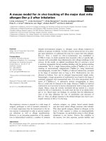
Fig. 1. Model of rain –wind induced cable vibration
The
relative
of mean wind to the cable with moving rivulet is
rain-wind induced velocity
cable vibration
2
æ
ö æ
ö
= ç U cos g 0 + R q cos (q + q 0 ) ÷ + ç U sin g + y + R q sin (q + q 0 ) ÷
The effective wind speed and wind angle effectUinrel the
ècable plane are given
ø by
è [11] as
ø
.
U = U0
.
.
,
(3)
where R is the radius of the cable, and the size of the rivulet is neglected.
2
oscillations
cos2 βThe
+ sin
αsin2 βof the rivulet are assumed to be harmonic
(1)
q = am sin (wt ) ,
and
2
(4)
(c)
where am denotes the amplitude
and w is the rivulet frequency equal to that of th
be a function of wind speed U (Wilde et al. [12]) a
αissin
β
cable.sin
Fig. 1. Model of rain –wind induced cable vibration
−1
considered
to
a
m
0
(2)
γ0 = εsin
(c) cable
The relative velocity of mean wind to the
with moving
rivulet is2
2
2
cos2 β + sin αsin β
2
Fig. 1. Model
of rain –wind
induced
cable
vibration
.
.
.
4
æ
ö æ
ö
U rel = ç U cos g 0 + R q cos (q + q 0 ) ÷ + ç U sin g + y + R q sin (q + q 0 ) ÷ , (3)
The where
relative εvelocity
of mean wind
to theWhen
cable with
rivulet
is γ is the angle of attack for the cylinder
is an influence
factor.
ε ismoving
selected
as 1,
è
ø
è
ø
0
and
when
ε2 size
is set
zero
it isisneglected.
the same as2 that on the cable without rivulet and yaw
R is the rivulet,
wherewithout
radius of .the
cable,
and the
of the
rivulet
.
.
æ The effects
ö æ wind
ö , (3)the cylinder axis and wind turbulence
Theçoscillations
rivulet
are
assumed
to
be
harmonic
angle.
of
the
mean
speed
component
U rel =
U cos g 0 +ofRthe
q cos
q
+
q
+
U
sin
g
+
y
+
R
q
sin (q + q 0 ) ÷along
(
ç
0 )÷
ø
areènot considered. q = am sinø (wtè) ,
(4)
where R is the
radius
of thevelocity
cable, and
sizewind
of theto
rivulet
is neglected.
The
relative
of the
mean
the cable
with moving rivulet is
where
thethe
amplitude
is the rivulet
am denotes of
The oscillations
rivuletand
are w
assumed
to be frequency
harmonicequal to that of the
cable. am is considered to be a function of wind speed U 0 (Wilde et al. [12]) as
.
2
(4)γ
Urel =q = amUsin
coswγt 0, + R θ cos (θ + θ0 ) + U sin
( )
.
.
+ y +R θ sin (θ + θ0 )
2
(3)
4
where am denotes the amplitude and w is the rivulet frequency equal to that of the
where R is the radius of the cable, and the size of the rivulet is neglected.
cable. am is considered to be a function of wind speed U 0 (Wilde et al. [12]) as
The oscillations of the rivulet are assumed to be harmonic
4
θ = am sin (ωt)
(4)
where am denotes the amplitude and ω is the rivulet frequency equal to that of the cable. am is considered to be a function of wind speed U0 (Wilde et al. [12]) as follows:
am (U0 ) = a1 exp −
(U0 − Umax )2
a2
(5)
where a1 , a2 and Umax are constants to be determined for a given cable.
Based on the assumption about the equality between the angular frequency of the rivulets and
the cable, wind angle effect on cable of RWIV is considered as the following function harmonic
35
Hung, T. V., Viet, V. Q. / Journal of Science and Technology in Civil Engineering
oscillation around the equilibrium position is the initial angle of impact (γ0 ), and its angular frequency
equals that of the rivulet and cable:
φ∗ = γ0 + a p sin (ωt)
(6)
where a p denotes the amplitude of the oscillation of real wind angle effect.
Clearly, a p depends on the wind velocity (U0 ), amplitude (am ) and initial position (θ0 ) of the
rivulet. When the oscillation of real wind angle effect is maximum (φ∗ = γ0 + a p ), the velocity of
cable is selected .as zero. Assume that effect of oscillation of the rivulet on cable is considered as
y
.
maximum (Rθ),
<< 1, a p is given as
U
a p = tan−1
U sin γ0 + Ram ω sin θ0
− γ0
U cos γ0 + Ram ω cos θ0
(7)
Eq. (7) indicates that when there is the absence of rivulet harmonic motion, real wind angle effect
will be unchanged and set as γ0 .
The aerodynamic force on the cable per unit length in the y axis is
2
ρDUrel
C L (φe ) cos φ∗ + C D (φe ) sin φ∗
(8)
2
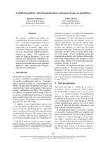
where ρ is the density of the air, D is the diameter of the cable, C D and C L are the drag and lift
coefficients. The coefficients C D and C L taken from [10] and [18] are depicted in Fig. 2. Angle φe is
computed by the following formula:
φe = φ∗ − θ − θ0
(9)
F=
The equation of vertical oscillation of the cable can be written as:
..
.
F
y +2ξ2 ω y +ω2 y = −
(10)
m
where ξ s is the structural damping ratio of the cable; m is the mass of the cable per unit length.
C D and C L are given as the quadratic functions
of φe as follows:
C D = D1 φ2e + D2 φe + D3
(11a)
C L = L1 φ2e + L2 φe + L3
(11b)
Substituting Eqs. (3), (6), (7) and (11) into
Figure 2. Chart of C D and C L (Angle of attack φe ,
Eq. (8) and then expanding the sine and cosine
Fig. 2. Chart of CD and deg)
C L (Angle of attack
functions aerodynamic forces are obtained as follow:
fe , deg)
1
fe as follows
are. given as the quadratic functions of (12)
CD Fand
= CFLdamp y +Fexc
m
m
CD = D1fe2 + D2fe + D3 ,
where
Fdamp
S 1 + S 2 sin (ωt) + S 3 sin (2ωt) + S 4 sin (3ωt) + S 5 sin (4ωt) +
Dρ S 6 sin (5ωt) + S 7 sin (6ωt) + S 8 sin (8ωt) + S 9 cos
CL = L1fe2 +(ωt)
L2f+e + L3 .
=
2 S 10 cos (2ωt) + S 11 cos (3ωt) + S 12 cos (4ωt) + S 13 cos (5ωt) +
S 14 cos (7ωt)
(13)
Substituting Eqs. (3), (6), (7) and (11) into Eq. (8) and then expandin
36
cosine functions aerodynamic
forces are obtained as follow:
.
F 1æ
= ç Fdamp . y + Fexc ö÷ ,
m mè
ø
Hung, T. V., Viet, V. Q. / Journal of Science and Technology in Civil Engineering
Fexc
X1 + X2 sin (ωt) + X3 sin (2ωt) + X4 sin (3ωt) + X5 sin (4ωt)
Dρ +X6 sin (5ωt) + X7 sin (6ωt) + X8 cos (ωt) + X9 cos (2ωt)
=
2 +X10 cos (3ωt) + X11 cos (4ωt) + X12 cos (5ωt) + X13 cos (6ωt)
+X14 cos (7ωt)
(14)
where S i and Xi can be found in Appendix. Eq. (10) can be rewritten as
..
.
y + 2ξ s ω + Fdamp y +ω2 y + Fexc = 0
(15)
Eq. (15) indicates that effects of RWIV create two forces on the cable, while Fexc is the exciting
force, Fdamp is the aerodynamic damping force which changes damping ratio of motion over time.
They are not only the functions of cable inclination, wind yaw angle, and the mean wind speed but
also the function of time, drag and lift coefficients.
3. Numerical results and discussion
In this section, various numerical examples are presented and discussed to verify the accuracy of
the new assumption and calculating results in SDOF model of RWIV. The first two examples focus
on evaluating the numerical results with the previous results. The next two examples investigate the
influence of other factors on vibrations of the cable.
3.1. Example one
In first example, the case of cable in [10, 12] will be discussed. The cable has the following
properties: mass per unit length m = 10.2 kg, diameter D = 0.154 m, structural damping ratio ξ s =
0.007. The coefficients C D and C L are taken from Fig. 2. Rain-wind induced vibrations appear at 7
m/s wind mean speed and disappear after 12 m/s (Flamand et al. [4]). The coefficients in Eq. (5) are:
Umax = 9.5 m/s, a1 = 0.448 and a2 = 1.5842. Eq. (15) is solved by using the fourth order Runge–Kutta
method with the initial conditions y0 = 0.001 m, y˙ 0 = 0. The inclination and the yaw angles are
assumed to be 45◦ .
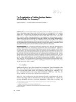
Firstly, the cable response for cable frequency f =1 Hz is studied. Fig. 3 shows the time history of
displacement response of the cable for wind speed U0 = 9.5 m/s. It indicates that harmonic oscillator
is formed with amplitude stability after a period. Fluctuation range of cable depending on the wind
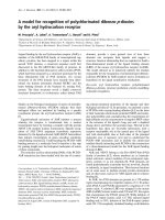
velocity can be seen more clearly in Fig. 4. Maximum cable vibration amplitude is surveyed for
three different cable frequencies: 1, 2 and 3 Hz, in the wind speed range from 5.5 to 4 m/s. Cable
amplitude reaches a maximum value at max wind speed of 9.5 m/s and then decreased rapidly with
wind speed velocity decreases to 7 m/s or increases to 12 m/s. Computed results are compared with
the experimental ([1]) and numerical ([12]) results. The similarity of the calculated and experimental
results indicates the dependence of not only the maximum value but also the changing trend of cable
amplitude on the wind speed. The only difference is the wind speed range in which occurs rain-wind
induced vibration. In this regard, the experimental results are also quite different as: wind speed range
according to Yamaguchi et al. [10] is (7.0, 12.0 m/s), Hikami et al. [1] is (8.0, 14.0), Li et al. [19] is
(6.76, 8.04). Besides, they have great differences compared to numerical results in [12] on not only
the values but also the characteristics of cable motion outside the affected RWIV area of wind speed.
When there is no appearance of rivulet fluctuations, the largest amplitude of the cable is not set as
zero explaining that the cable continues to fluctuate due to the effects of wind. This is explained by
assuming the real wind angle effect as a function of rivulet fluctuation amplitude. When the vibrations
of the water disappear, the real wind angle effect will be constant and the cable is only influenced by
the effects of wind.
37
disappear after 12 m/s (Flamand et al. [4]). The coefficients in Eq. (5) are: U max =9.5
m/s, a1 = 0.448 and a2 =1.5842. Eq. (15) is solved by using the fourth order Runge –
.
Kutta method with the initial conditions y0 = 0.001 m, y0 = 0. The inclination and the
Hung,
T. V.,are
Viet,
V. Q. to
/ Journal
yaw angles
assumed
be 450. of Science and Technology in Civil Engineering
Fig. 3. Cable response with f =1 Hz
Figure 3. Cable response with f = 1 Hz
(a) Computed vs. Wilde [12]
7
Computed vs.
(a)(a)Computed
vs.Wilde
Wilde[12]
[12]
Hikami and
and Shiraishi
[1] [1]
(b)(b)Hikami
Shiraishi
Fig. 4. Maximum cable vibration amplitude for different frequencies
Firstly, the cable response for cable frequency f =1 Hz is studied. Fig. 3 shows
Figure 4. Maximum cable vibration amplitude for different frequencies
the time history of displacement response of the cable for wind speed U 0 = 9.5 m/s. It
indicates that harmonic oscillator is formed with amplitude stability after a period.
Fluctuation range of cable depending on the wind velocity can be seen more clearly in
Fig. 4. Maximum cable vibration amplitude is surveyed for three different cable
In this example, the case of cable in [5] will frequencies:
be analysed.
The inclination and the yaw angles are
1, 2 and 3 Hz, in the wind speed range from 5.5 to 4 m/s. Cable amplitude
◦
◦
30 and 35 , respectively. The properties of cablereaches
as follow:
mass
per
unit
length
6 kg,
diameter
a maximum
value
at max
wind
speed ofm
9.5=m/s
and then
decreased D
rapidly with
wind speed velocity
decreases
7 m/s
or ranges
increases to
m/s.vibration
Computed results are
= 0.12 m, structural damping ratio ξ = 0.14%. According
to Gu
et al. to[5],
the
of12the
3.2. Example two
s
angle of the upper rivulet for this case are presented in Fig. 6 with the definition
of position of
8
upper rivulet as in Fig. 5. The angle of attack in the plane normal to the cable axis γ0 = 19.30. The
coefficients C D (b)
and
C L are
taken from
[6] as below:
Hikami
and Shiraishi
[1]
Fig. 4. Maximum cable vibration amplitude for different frequencies
− 30.2329
C D =f =1
−0.2498
∗ φ2eFig.
Firstly, the cable response for cable frequency
Hz is studied.
shows
∗ φe + 0.8416
(16a)
the time history of displacement response of the cable for wind speed U20 = 9.5 m/s. It
C L = 0.2436 ∗ φe + 0.3622 ∗ φe + 0.0647
(16b)
indicates that harmonic oscillator is formed with amplitude stability after a period.
The range of the effect of rain-wind induced vibrations is from U0 = 7 m/s to 12 m/s, but the
Fluctuation range of cable depending on the wind velocity can be seen more clearly in
wind
speed
is Umax
= 9.0 m/s
in accordance
Fig. 4. maximum
Maximum cable
vibration
amplitude
is surveyed
for three
different cable with experimental results in [5]. Calculated
frequencies:
1,
2
and
3
Hz,
in
the
wind
speed
range
from
5.5
to
4
m/s.
Cable
amplitude
results are presented in Fig. 7 with three different frequencies:
1 Hz, 1.7 Hz and 2.1 Hz, and compared
reaches a maximum value at max wind speed of 9.5 m/s and then decreased rapidly with
with the observed ones [5]. It shows that there is a small difference between two results when the
wind speed velocity decreases to 7 m/s or increases to 12 m/s. Computed results are
frequency of cable is as 1 Hz. The maximum cable oscillation amplitude is 32 cm at U0 = 9 m/s, and
8
it declines gradually corresponding
with the increase of difference between wind velocity and Umax .
However, in the experimental results, when the wind speed U0 > Umax cable vibration amplitude
drops suddenly in the value by 8 cm and stabilizes when the wind velocity in the range [10, 12]
(m/s). Increasing the natural frequency of cable, the amplitude of oscillation decreases rapidly, but
the decrease of two comparative cases is quite different. Experimental results show that the maximum
amplitude reduces dramatically when frequency raises, for example, amplitude for f = 1.7 Hz is only
38
the range [10, 12] (m/s). Increasing the natural frequency of cable, the amplitude of
oscillation decreases rapidly, but the decrease of two comparative cases is quite different.
Experimental results show that the maximum amplitude reduces dramatically when
1
frequency raises, for example, amplitude for f =1.7 Hz is only about
of that for 1
6
Hung, T. V., Viet, V. Q. / Journal of Science and Technology in Civil Engineering
1
1 Hz, this ratio is calculated about 3 . Although there
1 is the quantitative difference between
about of that for 1 Hz, this ratio is calculated about . Although there is the quantitative difference
6 the numerical and the experimental results, the quantities
3
character is preserved. That is
between the numerical and the experimental results, the quantities character is preserved. That is an
an increase of the stiffness of the cable to make the oscillation amplitude decrease, and
increase of the stiffness of the cable to make the oscillation amplitude decrease, and the position of
the position
of that
corresponding
that corresponding
wind
velocity
Umax . wind velocity U max .
Fig. 5.5.Definition
position
ofof
upper
rivulet
forfor
using
Fig.
6 6
Figure
Definitionofof
position
upper
rivulet
using
Fig.
Fig. 6. Inclination and wind yaw angles with position of upper rivulet [5]
10
Fig. 6. Inclination
wind yaw angles
with position
of upper
rivulet [5] Fig.
Figure 6.and
Inclination
and wind
yaw angles
with
Figure
7. Maximum
amplitude
7. Maximum
cable cable
amplitude
with a
position of upper rivulet [5]
3.3. Example three
β = 35
◦
with
35◦0,
=
300 ,α b= =30
3.3. Example Three
Two above examples demonstrate that the new assumption has fairly consistent
results with experiment ones. In this example, the case in example one will be considered
from the effects of rivulet oscillation components to cable motion. Amplitude ( am ) and
Two above examples demonstrate that the new assumption has fairly consistent results with exangle ( qone
rivulet
wind velocity
( U 0 the
) areeffects
the mainofobjects
of the survey.
periment ones. In this example, the case initial
in example
beand
considered
from
rivulet
0 ) of will
oscillation components to cable motion. Amplitude (am ) and initial angle (θ0 ) of rivulet and wind
velocity (U0 ) are the main objects of the survey. The hundreds data has been collected through solv11
ing Eq. (15) by the Runge–Kutta method; the results are presented in Figs. 8 to 10. In Fig. 7, cable
0
Fig. 7. Maximum
cable amplitude
with a = to
, b variation
= 35
300the
amplitude
is calculated
according
of U0 from 7 to 11.5 (m/s) and am from 0.05 to 0.45
(rad). Clearly, when wind speed is constant, cable amplitude is proportional to oscillation amplitude.
3.3. Example Three
Two above examples demonstrate that the new assumption has fairly consistent
This relationship seems to be linear increase reflected in the range of relative uniform. When wind
results with experiment ones. In this example, the case in example one will be considered
speed increases, cable amplitude also rises but after the value of Umax it does not change much in
from the effects of rivulet oscillation components to cable motion. Amplitude ( am ) and
terms of constant am . This survey demonstrates that, due to the fact that cable amplitude reaches the
value at Umax (and
am the
is reduced
when
initial angle ( qmaximum
main objects
of thewind
survey.speeds continue to increase above U max .
U 0 ) are
0 ) of rivulet and wind velocity
11
39
Hung, T. V., Viet, V. Q. / Journal of Science and Technology in Civil Engineering
Fig. 8. Cable response due to rivulet amplitude
Fig. 8. Cable response due to rivulet amplitude
Figure 8. Cable response due to rivulet amplitude
Fig. 10. Cable response due to initial angle and amplitude of rivulet
Fig. 9. Cable response due to initial angle of rivulet
Figure 9. Cable response due to Fig.
initial
angle
of due to initial
Figure
10.of Cable
9. Cable
response
angle
rivulet response due to initial angle and
rivulet
amplitude of rivulet
3.4. Example Four
In last example, the aerodynamic forces will be discussed through the model in
example one. From Eq. (12), aerodynamic force is obtained as follows:
The effects of initial13 angle (θ0 ) of rivulet on cable amplitude are presented
in Fig. 9. Nine cases
.
13
.
F
=
F
.
y
+
F
of θ0 from 450 to 690 are used to survey. The rivulet oscillation amplitude is unchanged
and as 0.25(17)
(rad). As be shown, when θ0 is constant, the relationship
between
motionforce
amplitude
and
velocity
of
Eq. (17) shows
that aerodynamic
is a harmonic
equation,
and contains
two
the wind is linear, expressed through the straight
line relationship
between
two quantities
Fig. the
9. resistant
components
have different
roles. Fdamp in
changes
Fdamp and Fexc which
Similarly, when the wind speed is unchanged, the oscillation amplitude increases as θ0 rises. The relcoefficient ofthem
the structure
while
exciting
force causing oscillation
of cable. Fig.
Fexc isThe
ative uniform growth shows the relationship between
is also
linear.
simultaneous
increase
of U0 and θ0 makes the cable vibration amplitude
increases
faster,
in contrast
the results
of experi11 presents
time history
of aerodynamic
forceto
calculated
as Eq. (17)
with wind velocity
as 9.5 m/s
frequency
cable as 1 Hz.
It indicates
force is increases.
a harmonic oscillation,
ments. Thus, this study shows that the initial angle
of and
rivulet
willofdecrease
when
windthespeed
and at and
the beginning
of the of
motion
is unstableIn
andthis
fluctuates
large veamplitude, in
Fig. 10 clarifies the impact of the initial position
amplitude
theitrivulet.
case,with
wind
contrast to the cable in this period with small amplitude.
locity is constant and as 9.5 m/s. As mentioned above,
the linear relationship between cable amplitude
The range of impact force according to wind velocity is displayed in Fig. 12. The
with θ0 and am is expressed again.
amplitude of the force is stable without the presence of rivulet oscillation and influence
damp
exc
of the wind speed. It increases and peaks at U max when RWIV occurs, while the
magnitude of the aerodynamic force rises continuously following the development of
14
40
Hung, T. V., Viet, V. Q. / Journal of Science and Technology in Civil Engineering
3.4. Example four
In last example, the aerodynamic forces will be discussed through the model in example one.
From Eq. (12), aerodynamic force is obtained as follows:
F = Fdamp y˙ + Fexc
(17)
results. that aerodynamic force is a harmonic equation, and contains two components
Eq. (17) shows
The fluctuating
characteristics
exciting
force the
are presented
Fig. 15 after
Fdamp and Fexc which
have different
roles. Fofdamp
changes
resistant in
coefficient
of the structure
neglecting
the
constant
components.
Similar
to
damping
force,
due
to
the
presence
of
while Fexc is exciting force causing oscillation of cable. Fig. 11 presents time history of aerodynamic
rivulet oscillation, exciting force fluctuating with amplitude increases gradually and
force calculated
as Eq. (17) with wind velocity as 9.5 m/s and frequency of cable as 1 Hz. It indicates
peaks
at windoscillation,
velocity U maxand
. When
does not occur,
exciting
forceitisisrelated
to theand fluctuates
the force is a harmonic
at RWIV
the beginning
of the
motion
unstable
with large amplitude, in contrast to the cable in this period with small amplitude.
wind velocity, the drag and lift coefficients of the cable.
Fig. 11.
11. Time
force
Figure
Timehistory
historyofofaerodynamic
aerodynamic
force
The range of impact force according to wind velocity is displayed in Fig. 12. The amplitude of
the force is stable without the presence of rivulet oscillation and influence of the wind speed. It
increases and peaks at Umax when RWIV occurs, while the magnitude of the aerodynamic force rises
continuously following the development of the wind velocity. It can conclude that the increase in the
aerodynamic force is not synonymous with the rise of cable vibration amplitude in RWIV. Probably
fluctuating characteristics of the new aerodynamic forces are the main causes; the more fluctuated
amplitude of aerodynamic forces in steady time increases, the bigger cable amplitude will be.
From Eq. (15) damping coefficient of vibration equation is as follows:
C = 2ξ s ω +
Fdamp
m
(18)
The amplitude of damping coefficient dependent of wind velocity is shown in Fig. 13. Cable
without rivulet oscillation has small damping coefficient change, but when RWIV occurs, the impact
Relationship
betweenchanging
impact force
cable response
force becomes unstableFig.
and12.generates
constant
ofwith
resistance
force. Corresponding to the
time of most unstable aerodynamic forces, oscillation amplitude of damping coefficient also reaches
the maximum value. As shown in Fig. 13, this value
16 is little change in the wind speed range from 9.5
m/s to 11.5 m/s, however, general trend average value increases continuously in RWIV area.
To examine the effects of damping coefficient to cable response, three cases of cable corresponding to maximum, minimum and average values will be discussed. New generated domain of cable
41
Fig. 11. Time history of aerodynamic force
Hung, T. V., Viet, V. Q. / Journal of Science and Technology in Civil Engineering
Fig. 12. Relationship between impact force with cable response
Figure 12. Relationship between impact force
with cable response
16
Fig. 13. Relationship between damping coefficient with cable response
Figure 13. Relationship between damping coefficient with
cable response
vibration amplitude is the set of values of the oscillation amplitude of the cable when damping coefficient is in the interval [minimum, maximum]. The cable amplitude in the case of average value of
damping coefficient is quite similar to cable response.
Contribution of aerodynamic damping can be calculated as the ratio [12]
Γ=
ξa
ξs
where ξa is aerodynamic damping ratio
(19)
Fig. 14. Contribution of aerodynamic damping
Fdamp
ξa =
(20)
2mω
Fig. 14 presents relationship between Γ and wind velocity computed with f = 1 Hz, compared with
the result in [12]. Aerodynamic damping fluctuates greatly when the cable subjects to wind and rain
combined effects. This fluctuation wane when the influence of rivulet oscillation decreases. These
fluctuating characteristics totally contrast to the results in [12]. It is attributed to the differences in
making the calculating assumptions. The new assumption of real impact angle presents more precise
Fig. 13. Relationship between damping coefficient with cable response
17
characteristics of aerodynamic damping, while old calculation method obtains particular results.
Fig. 15. Relationship between exciting force area and wind speed
Contribution of aerodynamic damping
FigureFig.
14.14.
Contribution
of aerodynamic damping
Figure 15. Relationship between exciting force
4. Conclusions
area and wind speed
New assumption of real impact angle of wind is successfully developed for single
degree-of-freedom model of rain-wind induced vibration. The new formulas calculating
of wind pressure on the cable are established. The correctness of the theory is
demonstrated through the comparison with experimental and numerical results. Lots of
models were examined to assess the effects of the parameters to the vibration of cable.
The following points can be outlined from the present study:
(a) Cable amplitude in model one is 18.3 cm when frequency of cable is as 1 Hz.
It decreases quickly when cable frequency increases.
(b) In the same survey condition, the relationship between initial position and
amplitude of rivulet with cable amplitude is linear.
(c) When rivulet amplitude is constant, maximum amplitude of rain-wind
The fluctuating characteristics of exciting force are presented in Fig. 15 after neglecting the constant components. Similar to damping force, due to the presence of rivulet oscillation, exciting force
42
17
induced vibration of cable changes very little with wind velocity over U
.
Hung, T. V., Viet, V. Q. / Journal of Science and Technology in Civil Engineering
fluctuating with amplitude increases gradually and peaks at wind velocity Umax . When RWIV does
not occur, exciting force is related to the wind velocity, the drag and lift coefficients of the cable.
4. Conclusions
New assumption of real impact angle of wind is successfully developed for single degree-offreedom model of rain-wind induced vibration. The new formulas calculating of wind pressure on
the cable are established. The correctness of the theory is demonstrated through the comparison with
experimental and numerical results. Lots of models were examined to assess the effects of the parameters to the vibration of cable. The following points can be outlined from the present study:
(a) Cable amplitude in model one is 18.3 cm when frequency of cable is as 1 Hz. It decreases
quickly when cable frequency increases.
(b) In the same survey condition, the relationship between initial position and amplitude of rivulet
with cable amplitude is linear.
(c) When rivulet amplitude is constant, maximum amplitude of rain-wind induced vibration of
cable changes very little with wind velocity over Umax .
(d) Aerodynamic force with two components damping force and exciting force are harmonic motions. The amplitudes of these oscillations are dependent to wind velocity, cable characteristics and
initial parameters of cable. However, they are not the major cause of cable oscillations with large
amplitude.
Acknowledgement
This research is funded by Vietnam National Foundation for Science and Technology Development (NAFOSTED) under grant number 107.01-2018.327.
References
[1] Hikami, Y., Shiraishi, N. (1988). Rain-wind induced vibrations of cables stayed bridges. Journal of Wind
Engineering and Industrial Aerodynamics, 29(1-3):409–418.
[2] Bosdogianni, A., Olivari, D. (1996). Wind-and rain-induced oscillations of cables of stayed bridges.
Journal of Wind Engineering and Industrial Aerodynamics, 64(2-3):171–185.
[3] Matsumoto, M., Shiraishi, N., Shirato, H. (1992). Rain-wind induced vibration of cables of cable-stayed
bridges. Journal of Wind Engineering and Industrial Aerodynamics, 43(1-3):2011–2022.
[4] Flamand, O. (1995). Rain-wind induced vibration of cables. Journal of Wind Engineering and Industrial
Aerodynamics, 57(2-3):353–362.
[5] Gu, M., Du, X. (2005). Experimental investigation of rain–wind-induced vibration of cables in cablestayed bridges and its mitigation. Journal of Wind Engineering and Industrial Aerodynamics, 93(1):
79–95.
[6] Gu, M. (2009). On wind–rain induced vibration of cables of cable-stayed bridges based on quasi-steady
assumption. Journal of Wind Engineering and Industrial Aerodynamics, 97(7-8):381–391.
[7] Costa, A. P. d., Martins, J. A. C., Branco, F., Lilien, J.-L. (1996). Oscillations of bridge stay cables
induced by periodic motions of deck and/or towers. Journal of Engineering Mechanics, 122(7):613–622.
[8] Ni, Y. Q., Wang, X. Y., Chen, Z. Q., Ko, J. M. (2007). Field observations of rain-wind-induced cable
vibration in cable-stayed Dongting Lake Bridge. Journal of Wind Engineering and Industrial Aerodynamics, 95(5):303–328.
[9] Wu, T., Kareem, A., Li, S. (2013). On the excitation mechanisms of rain–wind induced vibration of cables:
Unsteady and hysteretic nonlinear features. Journal of Wind Engineering and Industrial Aerodynamics,
122:83–95.
43
Hung, T. V., Viet, V. Q. / Journal of Science and Technology in Civil Engineering
[10] Yamaguchi, H. (1990). Analytical study on growth mechanism of rain vibration of cables. Journal of
Wind Engineering and Industrial Aerodynamics, 33(1-2):73–80.
[11] Xu, Y. L., Wang, L. Y. (2003). Analytical study of wind–rain-induced cable vibration: SDOF model.
Journal of Wind Engineering and Industrial Aerodynamics, 91(1-2):27–40.
[12] Wilde, K., Witkowski, W. (2003). Simple model of rain-wind-induced vibrations of stayed cables. Journal
of Wind Engineering and Industrial Aerodynamics, 91(7):873–891.
[13] Lemaitre, C., Hémon, P., De Langre, E. (2007). Thin water film around a cable subject to wind. Journal
of Wind Engineering and Industrial Aerodynamics, 95(9-11):1259–1271.
[14] Bi, J. H., Wang, J., Shao, Q., Lu, P., Guan, J., Li, Q. B. (2013). 2D numerical analysis on evolution
of water film and cable vibration response subject to wind and rain. Journal of Wind Engineering and
Industrial Aerodynamics, 121:49–59.
[15] Li, S., Gu, M., Chen, Z. (2007). Analytical model for rain-wind-induced vibration of three-dimensional
continuous stay cable with quasi-moving. Engineering Mechanics, 24(6):7–14. (in Chinese).
[16] Li, H., Chen, W.-L., Xu, F., Li, F.-C., Ou, J.-P. (2010). A numerical and experimental hybrid approach
for the investigation of aerodynamic forces on stay cables suffering from rain-wind induced vibration.
Journal of Fluids and Structures, 26(7-8):1195–1215.
[17] Zhan, S., Xu, Y. L., Zhou, H. J., Shum, K. M. (2008). Experimental study of wind–rain-induced cable
vibration using a new model setup scheme. Journal of Wind Engineering and Industrial Aerodynamics,
96(12):2438–2451.
[18] Gu, M., Lu, Q. (2001). Theoretical analysis of wind-rain induced vibration of cables of cable-stayed
bridges. Journal of Wind Engineering and Industrial Aerodynamics, 89:125–128.
[19] Li, F.-C., Chen, W.-L., Li, H., Zhang, R. (2010). An ultrasonic transmission thickness measurement system for study of water rivulets characteristics of stay cables suffering from wind–rain-induced vibration.
Sensors and Actuators A: Physical, 159(1):12–23.
Appendix
1
1
A1 = L3 + L1 a2m + L1 θ02 − L2 θ0 + γ0 L2 + D3 + D1 γ02 − D2 γ0 + D1 a2m
2
2
1
1
1
+ a p am D1 θ0 − D2 − L1 a2m a2p (1 + 2γ0 ) − a p am γ0 L1 + L1 θ0 + 2D1
2
16
2
3
1
1
1
1
1
+ a2p + γ0 + a2p γ0 + γ03 L1 − L2 θ0 − L3 − L1 θ02 − 2D1 θ0 + D2 − L1 a2m
2
2
2
2
2
4
1
1
7
7 2 5 2
1
+ D1 am a p − a3p + a2p γ0 + 4γ03 − D1 a2p γ0
a p + γ0 − D1 γ05
6
8
4
24
6
6
1
3 2
1
1
1
1
1 4
− a p am a p + 3γ02
L2 + L1 + 2D1 − L1 − D1 θ0 + D2
a + 3a2p γ02 + γ04
2
4
2
2
3
6
8 p
44
(A1)
Hung, T. V., Viet, V. Q. / Journal of Science and Technology in Civil Engineering
1
5
1
A2 = am (2L1 θ0 − L2 ) + a p L2 + D3 + D1 θ02 − D2 θ0 + D1 a2m − D1 a p a4p + 7a2p γ02 + 5γ04
2
6
8
1
9
1
− am a2p + 2a2p γ0 + γ02 + γ03
L2 + L1 θ0 + 2D1 + L1 am γ0 a2p + γ02 − 2
4
2
4
3
1
1
1
1
+ a p a2p + 3γ02 + 2γ0 L1 − L2 θ0 − L3 − L1 θ02 − 2D1 θ0 + D2 − L1 a2m
4
2
2
2
4
3
1
1
+ L1 a2m a p 2 − a2p + 3γ02 − 2γ0 + L1 θ0 a2p + 3γ02 − a3p − 8a p + am γ0 (2D1 θ0 − D2 )
8
2
4
1
1
1
1
1
1
L1 − D1 θ0 + D2 + D1 am a4p + 3a2p γ02 + γ04
− − a4p + 3a2p γ02 + γ04
8
2
3
6
3
8
(A2)
1 2
1
1
1
3 5 2
2
A3 = − a p am L2 + L1 θ0 + 2D1 + 3L1 γ0 + D1 a p a p + 11γ0 + am a p
4
2
24
4
2
1
1
1
1
1
1
− a2p L1 − L2 θ0 − L3 − L1 θ02 − 2D1 θ0 + D2 − L1 a2m − D1 a2m a p
4
2
2
2
4
4
3
1
1
1
1
1
1
+ L1 a2m a p a2p + 3γ02 + 2γ0 + a p a2m γ0 (L1 + L2 + 2D1 ) + a3p γ0 L1 − D1 θ0 + D2
8
4
2
2
2
3
6
(A3)
A4 = −
1
1
1
L1 a2m a3p + D1 am a4p − D1 a4p
32
48
6
(A4)
1
1
1
A5 = − D1 a2m γ0 + a p γ0 am L2 + L1 θ0 + 2D1 + L1 + D2 − D1 θ0 am a p
2
2
2
1
1
1
7
1
1
+ am a p L2 + L1 + 2D1 a2p + 3γ02 − D1 γ0 a2p a2p + 3γ02 + L1 a2m a2p + γ02 − 2
2
2
4
4
4
2
1
1
5
1
1
1
+ γ0 L1 − L2 θ0 − L3 − L1 θ02 − 2D1 θ0 + D2 + L1 a2m γ0 a2p + γ02
− a2p
2
2
2
2
4
2
3
1
1
1 3 7 2
1
− L1 a p γ0 am γ0 + a p + a p (3L1 − 2D1 θ0 + D2 ) − a p + a p γ0 + 4γ03 − D1 am a3p γ0
2
4
12
8
4
12
(A5)
1
1
1
L1 a2p a2m (1 + 2γ0 ) − am a3p (L2 + 2L1 + 4D1 ) − a4p (3L1 − 2D1 θ0 + D2 )
16
16
48
1
7
+ D1 a3p γ0 am − a p
4
12
(A6)
B1 = 2U sin (γ0 )
(A7)
A6 = −
B2 = Ra2m ω 1 −
45
1 2 1 2
a − θ
12 m 2 0
(A8)
Hung, T. V., Viet, V. Q. / Journal of Science and Technology in Civil Engineering
1
1
B3 = Ram ωθ0 2 − θ02 − a2m
3
4
Adamp
A1 A2
= 0 0
0 0
0
A3
0
A4
A5
2A1 − A6
0
0
2
2
A2 + A3
A3 + A4
0
0
2
2
0
A5
0
A6
0
A4 − A2
A3
A2 + A3
0
0 −
2
2
2
2A1 + A5
A5 + A6
A6
0
0
2
2
2
1
C1 = U 2 + R2 a2m ω2
2
C2 = URa2m ω 2 −
C3 =
5 2
a sin (γ0 − θ0 )
24 m
1
URa4m ω sin (γ0 − θ0 )
24
C4 = URam ω 2 −
a2m
cos (γ0 − θ0 )
4
(A9)
0
A6
2
A4
2
0
0
0
0
A4
−
2
0
(A10)
(A11)
(A12)
(A13)
(A14)
1
C5 = R2 a2m ω2
2
(A15)
1
C6 = URa3m ω cos (γ0 − θ0 )
4
(A16)
46
Hung, T. V., Viet, V. Q. / Journal of Science and Technology in Civil Engineering
[Aexc ] =
0
A1 − A6
2
A5
2
A2 + A3
2
A1
A2
0
0
0
0
0
0
A5
2
A3 − A2
2
0
0
0
A2 + A3
2
A3 + A4
2
A1 + A5
2
0
A5 + A6
2
0
−
0
0
A6
2
A1 + A4
2
A4
0
A1
0
0
A3 + A4
2
0
0
A3
2
0
A2 + A4
2
A2
2
A5
0
A5
2
A3
0
0
A4 − A2
2
A2
2
A5
2
0
A6
0
0
A2
2
0
A3
−
2
A2
−
2
0
0
0
0
0
0
A6
2
A5
2
A4
2
0
A3
2
0
A4
−
2
A3
−
2
0
0
A6
2
0
0
A5
2
0
0
0
A1
0
A5
2
A4
2
A6
2
(A17)
[S 1 S 2 ... S 14 S 14 ] = [B1 B2 B3 ] . Adamp
(A18)
[X1 X2 ... X13 X14 ] = [C1 C2 ... C5 C6 ] . [Aexc ]
(A19)
47