Field monitoring on piled raft foundation subjected to unsymmetrical earth pressure
Bạn đang xem bản rút gọn của tài liệu. Xem và tải ngay bản đầy đủ của tài liệu tại đây (542.82 KB, 4 trang )
Field monitoring on piled raft foundation subjected
to unsymmetrical earth pressure
Quan trắc hiện trường móng bè cọc chịu áp lực đất không đối xứng
J. Hamada(1), K. Yamashita(2)
Tóm tắt
Bài báo này giới thiệu nghiên cứu cụ thể về
công trình nhà bảy tầng với ba tầng hầm,
chịu áp lực đất không đối xứng. Để giảm
thiểu độ lún quá lớn do các lớp đất sét dưới
bè móng và để giảm lực cắt phát sinh lớn
tác động lên cọc do lực ngang từ áp lực đất,
phương án móng bè cọc đã được sử dụng. Để
khẳng định tính đúng đắn của phương án
thiết kế móng này, công tác quan trắc dài hạn
sự phân chia tải trọng giữa bè và cọc đã được
tiến hành bằng các phép đo trong khoảng
thời gian 13 năm. Dựa trên các kết quả đo
được của tòa nhà cho thấy rằng móng bè cọc
không những chịu tốt tải trọng đứng của
công trình mà còn có thể chịu được tải trọng
ngang do áp lực đất không đối xứng.
Từ khóa: móng bè cọc, đo đạc hiện trường, áp lực đất
không đối xứng, phân chia tải trọng
Abstract
This paper offers a case history of a seven-story
building with three basement floors, subjected to
unsymmetrical earth pressure. To reduce excessive
settlements due to clay layers below the raft,
and to reduce excessive shear force acting on
piles due to lateral load from earth pressure, a
piled raft foundation was employed. To confirm
the validity of the foundation design, long-term
field measurements on the foundation have been
conducted on the load sharing between the raft
and the piles during about thirteen years. Based
on the measurement results of the building, it is
confirmed that a piled raft foundation works well
not only for vertical structure load but also for
lateral load due to unsymmetrical earth pressure.
Keywords: piled raft foundation, field
measurements, unsymmetrical earth pressure, load
sharing
(1) Dr, Group Leader, Research &
Development Institute, Takenaka Corporation,
(2) Dr, Executive Manager, Research &
Development Institute, Takenaka Corporation,
1. Introduction
Piled raft foundations are recognised as one of the most economical foundation
system, and have been applied for a lot of building in many countries such as
Germany and Japan. Several case histories have been reported about piled
rafts [1, 2, 3]. However, only a few case histories exist on the monitoring of the
soil-pile-structure interaction behavior for lateral load. This paper offers a case
history of a piled raft foundation focusing on pile bending moments in addition to
vertical load sharing. During the monitoring period, the 2011 off the Pacific coast
of Tohoku Earthquake struck the site. Subsequently, the monitoring was frequently
conducted. In addition, the seismic observation records on the foundation have
been reported by Hamada et al. (2015) [4].
2. Monitored building and soil conditions
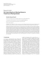
The monitored building, which is a seven-story residential building with
three basement floors, is located in Tokyo, Japan. The building subjected to
unsymmetrical earth pressure is a reinforced concrete structure, 29.3 m high, with
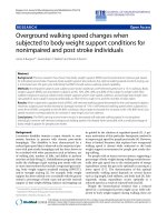
a 71.4 m by 36.0 m footprint. Figure 1 shows a schematic view of the building
and its foundation with a typical soil profile. The soil profile consists of fine sand
layer just below the raft with SPT N-values from 10 to 20 and clay strata including
humus between depths of 17 m and 24 m from the ground surface with unconfined
compressive strength of about 140 kPa. Below the depth of 24 m, there lies a
Pleistocene fine sand layer with SPT N-values of 40 or higher. The shear wave
velocities derived from a P-S logging system were about 200 m/s between the
depths of 17 m and 24 m, and 480 to 570 m/s in the sand layers below the depth
of 24 m. The ground water table appears at a depth approximately equal to the
basement level.
The average contact pressure over the raft was 159 kPa. If a conventional pile
foundation were used for the building foundation subjected to unsymmetrical earth
pressure, the piles should carry large lateral load not only for seismic condition but
also for ordinary condition, where a design horizontal seismic coefficient (lateral
load over building dead load) was 0.15 for ordinary condition and 0.34 for severe
seismic condition. On the other hand, if a raft foundation were used, the clay layer
between depths of 17 and 23 m has a potential of excessive settlement while the
sand layer just below the raft has enough bearing capacity for the dead load of
the building and lateral frictional resistance between the raft and the subsoil can
be reliable.
Consequently, a piled raft foundation consiting of cast-in-place concrete piles
with 1.2 m in diameter and 12.2 m in length was employed, where the lateral load
can be resisted by both the piles and the frictional resistance beneath the raft.
3. Instrumentation
To confirm the validity of the foundation design, field measurements were
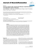
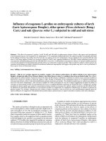
performed on the load sharing between the raft and the piles. Figures 2 and 3
show the layout of the piles with locations of monitoring decices. Axial forces and
bending moments of the piles were measured by a couple of LVDT-type strain
gauges on Pile_2D (2-D street), Pile_5G (5-G street) and Pile_5D (5-D street).
Eight earth pressure cells and a pore-water pressure cell were installed beneath
the raft around the instrumented piles. Three sections of Pile_5D at depths of 1.0
m, 2.0 m and 9.14 m below the pile head and those of Pile_5G at depths of 1.0 m,
1.7 m and 8.19 m were measured.
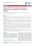
Earth pressure cells of D4 and D6 were set obliquely on the soil around
Pile_5D, as shown in Photo 1, in order to evaluate a frictional resistance beneath
the raft by the difference of the earth pressure from the two earth pressure cells.
Earth pressure cells of D8-1, D8-2 and D9 were set on the embedded side wall in
order to evaluate a lateral force acting on the side wall of the building.
S¬ 28 - 2017
79
KHOA H“C & C«NG NGHª
Figure 1. Schematic view
of monitored building and
foundation with soil profile
Figure 2. Foundation profile with locations of
monitoring devices
(a) Pile_5G
Photo 1. Inclined setting earth pressure cells (D4,
D5 and D6)
(b) Pile_5D
The axial forces and the bending moments of two piles,
the contact earth pressures between the raft and the soil as
well as the pore-water pressure beneath the raft were also
measured. The resolutions of strain and earth pressure are
about 1.0×10⁻⁴μ and about 5.0×10⁻⁶ kPa, respectively as
shown in table 1.
4. Long-term measurements
Figure 3: Locations of strain gauges on monitored
piles
80
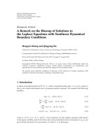
Figure 4 shows the time hisories of axial loads on
Pile_5D and Pile_5G. Figure 5 shows the relation of the axial
load at the pile head with those at the intermediate depth
and near the pile toe. Axial loads are about 4500-4000 kN
on pile head at Pile_5D, while about 600 kN near pile toe.
This means relatively large pile skin friction, ((4500-600)kN
/ (1.2π m x 7.14 m)=145 kPa). And axial load on pile head
are gradually increasing after the end of construction with
seasonal variation.
Figure 6 shows time histories of bending moments
on Pile_5D and Pile_5G, respectively. These values are
T„P CHŠ KHOA H“C KI¦N TR”C - XŸY D¼NG
(a) Pile_5D
(b) Pile_5G
Figure 4. Time histories of axial load on piles
(a) Pile_5D
(b) Pile_5G
Figure 5. Relationship of axial load between head load and intermediate depth
(a) Pile_5D
Figure 6. Time histories of bending moment on piles
Figure 7. Time histories of earth pressures and water
pressure around pile_5D
(b) Pile_5G
Figure 8. Time histories of earth pressures acting on
side walls
Table 1. Measuring devices
Istrument
Number
Resolution
Strain gauge
26
0.99 ~ 1.06 x 10⁻⁴ μ
Earth pressure cell
10
3.71 ~ 5.68 x 10⁻⁶ kPa
Piezometer
1
1.44 x 10⁻⁶ kPa
Figure 9. Time histories of load sharing between raft
and pile
S¬ 28 - 2017
81
KHOA H“C & C«NG NGHª
negligibly small. Figure 7 shows the time hisories of contact
earthpressures and water pressure beneath the raft around
Pile_5D. Measured values are relatively stable comparing
to axial load on pile. Figure 8 shows the time-dependent
earth presure acting on the embedded side walls. The
earth pressure was stable after the earthquake. Judging
from 55 kPa at D8-2, a coefficient of earth pressure K was
approximately evaluated as 0.3 (55 kPa / unit weight (17 kN/
m3) / depth (11.2 m)).
Tohoku Earthquake which a seismic intensity at the observed
building site was little less than 5.
5. Conclusions
Based on the long-term monitoring, no significant
changes in load sharing between the piles and the raft or
earth pressures acting on the side wall were observed after
the 2011 Tohoku Earthquake. Consequently, the foundation
design was found to be appropriate./.
The axial load of the pile and the earth pressures acting on
side wall fluctuate according to a season due to temperature.
The seasonal variation of the incremental earth pressures
of D8-2, D9 shows opposite relation, that is positive and
negative.
Tài liệu tham khảo
1. Poulos H.G., Piled raft foundations: design and applications,
Geotechnique 51(2), pp.95-113, 2001.
2. Katzenbach R., Arslan U. and Moormann C., Piled raft
foundation projects in Germany, Design applications of raft
foundations, Hemsley J.A. Editor, Thomas Telford, pp.323392, 2000.
Figure 9 shows the time-dependent load sharing among
the pile load (kPa), the earth pressure and the water pressure
in the tributary area of Pile_5D. The earth pressure is an
average of the measured values from D7 and D5. The pile
load (kPa) is estimated by the axial force of the pile divided
by the tributary area of 39 m2. The ratio of the load carried
by the pile to the total load is 40% (42%) at the end of the
construction and 43% (44%) about eleven years after that
time. Here, the values in parentheses are the ratios of the
load carried by the pile to the effective load. The ratios were
almost same before and after the 2011 off the Pacific coast of
3. Yamashita, K., Yamada, T. and Hamada, J., Investigation of
settlement and load shearing on piled rafts by monitoring
full-scale structures, Soil and Foundations, Vol.51, pp.513532, 2011.6.
4. Hamada, J., Aso, N., Hanai, A. and Yamashita, K., Seismic
performance of piled raft subjected to unsymmetrical earth
pressure based on seismic observation records, 6ICEGE,
2015.
Nghiên cứu thực nghiệm sự phá hoại và biến dạng...
(tiếp theo trang 61)
6. Kết luận và kiến nghị
Trên cơ sở phân tích sự phá hoại của các mẫu thí nghiệm
và biến dạng cắt của các nút khung có thể rút ra các kết luận
sau:
-Cách thức thiết kế khác nhau dẫn tới cách ứng xử khác
nhau của các mẫu thí nghiệm. Phá hoại mẫu NK1 là dạng
phá hoại dẻo với các khớp dẻo uốn xuất hiện ở các dầm sát
mặt cột. Phá hoại vùng nút khunglà phá hoại dẻo và có biến
dạng tương đối đều trên toàn bộ vùng nút. Phá hoại các mẫu
NK2 và NK3 thuộc dạng phá hoại giòn. Vùng nút khung ởhai
mẫu này bị ép vỡ dưới dưới tác động nén cục bộ của chuyển
vị xoay đầu mút cột và dầm. Các dầm và cột quanh nút khung
không phát triển được biến dạng dẻo đầy đủ và không hoàn
toàn là biến dạng uốn. Nguy cơ phá hoại (uốn và cắt) giữa
dầm, cột và nút khung gần ngang nhau.
Tài liệu tham khảo
1. Beckingsale C.W. Post-Elastic Behavior of Reinforced Concrete
Beam-Column Joints, Research Report 80-20, Department of
Civil Engineering, University of Canterbury, Christchurch, New
Zealand, August 1980.
2. Nguyễn Lê Ninh: Động đất và thiết kế công trình chịu động đất,
nhà xuất bản Xây dựng – 2007
3. Paulay T., Priestley M.J.N. “Seismic design of reinforced
concrete and masonry buildings”, John Wiley – 1992.
4. Sangjoon Park, Khalid M. Mosalam, Experimental and
Analytical Studies on Reinforced Concrete Buildings with
Seismically Vulnerable Beam- Column Joints, Pacific
Earthquake Engineering Research Center (PEER), 2012.
5. SP 14.13330.2011 -СТРОИТЕЛЬСТВО В СЕЙСМИЧЕСКИХ
РАЙОНАХ.
6. TCVN 9386:2012(2012),”Thiết kế công trình chịu động đất”,
Nhà Xuất bản Xây Dựng, Hà Nội.
82
- Dưới tác động cắt và uốn của dầm và cột truyền vào,
các nút khung sẽ bị biến dạng cắt đáng kể, ngay cả khi được
thiết kế theo các quy định của tiêu chuẩn thiết kế kháng chấn
hiện đại TCVN 9386:2012. Do đó, việc xét tới biến dạng của
nút khung trong tính toán hệ kết cấu khung BTCT chịu động
đất là hết sức cần thiết.
- Hiệu ứng bó bê tông trong vùng nút khung ảnh hưởng
quyết định tới ứng xử của nút khung. Để tạo được hiệu ứng
bó bê tông này vai trò của cốt đai và cốt thép cột trung gian
trong vùng nút khung hết sức quan trọng.
-Thí nghiệm cho thấy, các hệ kết cấu khung được thiết
kế theo tiêu chuẩn của Nga SP 14.13330.2014 và của Việt
Nam TCVN 5574:2012 không phù hợp để phát triển cơ cấu
phá hoại dẻo ở hệ kết cấu khung BTCTchịu động đất mạnh./.
7. TCVN 5574:2012(2012), “Kết cấu bê tông và bê tông cốt thép”,
Nhà Xuất bản Xây Dựng, Hà Nội.
8. A.K. Kaliluthin, S. Kothandaraman, T.S. Suhail Ahamed,
A Review on behavior of reinforced concrete beam-column
joint, International Journal of Innovative Research in Science,
Engineering and Technology, 2014.
9. Jaehong Kim, James M. LaFave. Joint Shear Behavior of
Reinforced Concrete Beam-Column Connections subjected to
Seismic Lateral Loading, Department of Civil and Environmental
Engineering University of Illinois, 2009.
10.Sangjoon Park, Khalid M. Mosalam, Shear strength models of
exterior Beam-column joints without transverse reinforcement.
Pacific Earthquake Engineering Research Center (PEER), 2009.
11.Nilanjan Mitra. An analytical study of reinforced concrete
beam-column joint behavior under seismic loading. University of
Washington, USA, 2007.
T„P CHŠ KHOA H“C KI¦N TR”C - XŸY D¼NG