Changes in microstructures and physical properties of polymer-modified mortars during wet storage
Bạn đang xem bản rút gọn của tài liệu. Xem và tải ngay bản đầy đủ của tài liệu tại đây (673.56 KB, 12 trang )
Cement and Concrete Research 36 (2006) 79 – 90
Changes in microstructures and physical properties of
polymer-modified mortars during wet storage
A. Jenni a,*, R. Zurbriggen b, L. Holzer c, M. Herwegh a
a
Institute of Geological Sciences, University of Berne, Berne, Switzerland
b
Elotex AG, Sempach Station, Switzerland
c
EMPA, Du¨bendorf, Switzerland
Received 15 December 2004; accepted 3 June 2005
Abstract
The decrease in strength of tile adhesive mortars during wet storage was investigated. In a first approach, the water resistance of the
polymer phases was tested on structures isolated from the mortar and in situ. It was observed that cellulose ether and polyvinyl alcohol
structures are water-soluble. Subsequent investigations on polymer mobility within the mortar showed that the migrating pore water
transports cellulose ether and polyvinyl alcohol during periods of water intrusion and drying. This leads to enrichments at the mortar –
substrate interface. In contrast, latices interacting with the cement are water-resistant, and therefore, immobile in the mortar. Further
experiments revealed that the mortar underwent considerable volume changes depending on the storage condition. Cracking occurred mainly
close to the mortar – tile interface, cement hydrates grew within these shrinkage or expansion cracks. Test results revealed that the strength
decrease of wet stored tile adhesives is caused by different mechanisms related to cement hydration, volume changes of the mortar, and
reversible swelling of latex films.
D 2005 Elsevier Ltd. All rights reserved.
Keywords: Mortar (E); Microstructure (B); Polymers (D); Wet storage; Shrinkage (C)
1. Introduction
Polymer-modification is widespread in cementitious
applications to improve the physical properties of building
materials. As many of these materials are exposed to wet
conditions during service life, numerous studies investigated
the influence of water storage on their physical properties.
Tile adhesives are commonly modified with cellulose
ether (CE) and redispersible powder (RP), the latter
containing latex and polyvinyl alcohol (PVA; for mortar
formulation see Table 1). Each of these polymers fulfils
different tasks during the mortar evolution [1]. CE thickens
the fresh mortar, entrains air during mixing and retains
* Corresponding author. EPFL – STI – IMX – LMC, MXG – Ecublens, CH1015, Lausanne, Switzerland. Tel.: +41 21 693 28 67; fax: +41 21 693 58 00.
E-mail addresses: (A. Jenni),
(R. Zurbriggen),
(L. Holzer), (M. Herwegh).
0008-8846/$ - see front matter D 2005 Elsevier Ltd. All rights reserved.
doi:10.1016/j.cemconres.2005.06.001
water. RPs mainly provide flexibility and tensile strength in
the hardened mortar. In contrast to concrete applications,
such tile adhesive mortars are prepared with a high w / c
(water / cement ratio) of approximately 0.8 and characterised
by high air void contents of more than 20 vol.%, and low
degrees of cement hydration (sometimes less than 50%, [1]).
The influence of water contact on the mechanical
properties of polymer-modified cementitious products, were
studied extensively [2 –5]. The investigations of Tubbesing
[6] include a microstructural characterisation of wet stored
polymer-modified mortars. Based on scanning electron
microscopy (SEM) images of fracture surfaces, Schulze
and Killermann [5] concluded that latex morphology
undergoes no structural changes, even after 10 years of
outdoor exposure. Other studies focussed on changing pore
size distributions due to water contact (e.g., [7– 9]). Water
intrusion and shrinkage/expansion of mortars were rarely
investigated [10], but more frequently in the field of
concrete (e.g., [11 – 14]). Mortar-specific aspects like hydro-
80
A. Jenni et al. / Cement and Concrete Research 36 (2006) 79 – 90
Table 1
Formulations used for ceramic tile adhesives
[wt.%] of
dry mix
Component
Details
35.0
Ordinary
portland
cement
Quartz sand
CEM I 52.5 R, Jura Cement Fabriken,
Wildegg, CH
40.0
22.5
0.5
2.0
25.5
Carbonate
powder
Cellulose
ether
Redispersible
powder
Water
0.1 – 0.3 mm, Zimmerli Mineralwerke AG,
Zu¨rich, CH
Durcal 65, average grain size 57.5 Am, Omya
AG, Oftringen, CH
MHEC 15000 PFF, Aqualon GmbH,
Du¨sseldorf, D
Noncommercial powders with different latex
compositions, whereof three types were tested:
— VC (vinyl-acetate/ethylene/vinyl-chloride
co-polymer)
— SA (styrene/acrylic co-polymer)
— EVA (ethylene/vinyl-acetate co-polymer)
All containing PVA, mean particle size in
dispersion d(0.5) of about 1 Am, Elotex AG,
Sempach Station, CH
Deionised
Note that the percentages relate to 100 wt.% of the dry mix. In lab mortars
with only one or two polymer types, mineral filler replaced the omitted
polymers.
phobicity (discussed in Ref. [15]) and the increased
importance of the mortar’s interface [16,17] have to be
considered. Beeldens [18] showed different drying rates of
films from alkaline and non-alkaline latex dispersions, but
did not investigate differences in other film properties.
In this study, we focus on polymer-related microstructures and on their changes during wet storage. Mechanisms
like water intrusion, polymer mobilisation and redistribution, cement hydration and dimensional changes influence
strength and were investigated by a variety of different
analytical techniques.
were performed. The amounts of NaOH and Ca(OH)2 were
chosen such that a pH value of 12.5 resulted, whereas the
CaCl2 concentration was adjusted to gain the same Ca2+
concentration as in the Ca(OH)2 solution. The polymer
concentrations in these deionised or cementitious waters
were 10% for the RP dispersion, 2% for the CE solution,
and 2.2% for the PVA solution. Dispersion or dissolution of
the polymers was achieved by ultrasonic treatment at 25
kHz/50 W for 2 min. A metal grid of 86 Am sized square
voids was dipped into the polymer solution or dispersion
immediately to avoid gravitational fractionation (Fig. 1a).
Evaporation of the water under room conditions increased
the polymer concentration and caused the formation of
polymer films in the voids of the grid. The amount of each
polymer used was carefully evaluated in advance to promote
formation of polymer films with a hole in the centre, which
characterises very thin films. This situation is, in terms of
film dimensions, similar to polymer films observed in air
voids of real mortars (Fig. 2a). After storage for at least 2
weeks under room conditions, the films were exposed to
deionised or synthetic cement water between two glass
slides, for time intervals ranging from 10 min up to 2
months (Fig. 1b). Water induced changes in the film
structure were observed by transmitted light microscopy
and qualitatively rated on a scale between 0 (complete
disintegration, Fig. 2a and b) and 1 (no major changes of the
film morphology, Fig. 2c and d).
The size of these artificial polymer films corresponds to the
polymer films in air voids (>10 Am) of real mortars. However,
care is required for extrapolating these experimental results to
the real mortar system. Cement–polymer interaction is not
restricted to the pore solution, but also occurs at various solid–
liquid interfaces, which can induce intergrowth of minerals and
polymers. Therefore, we also performed in situ studies on
polymer films in water stored mortars using an environmental
scanning electron microscope (ESEM).
2. Materials and methods
2.2. Environmental scanning electron microscopy
2.1. Light microscopy
The ESEM allowed in situ observation of microstructures
before and after water contact. The behaviour of the
polymeric microstructures during such water immersion
experiments revealed their water resistance.
To investigate the water resistance of polymer films,
experiments on the individual polymers were performed.
For this purpose, polymer powders were redispersed (RP) or
dissolved (CE/PVA) in water, e.g. with an ionic composition
representative of the pore water during early cement
hydration. In this context, three different types of aqueous
phases were used: (a) deionised water, (b) filtered cement
water, and (c) synthetic cement water (Table 2). The filtered
cement water derived from the same cement paste used in all
experiments of this study. This filtered water may deviate
from the true pore solution in the fresh mortar and therefore
synthetic cement water was used also, which is assumed to
represent a more realistic pore solution [19]. In case of RP
containing ethylene/vinyl-acetate latex (EVA), further
experiments in aqueous solution of NaOH, CaO, and CaCl2
Table 2
Composition and pH of filtered and synthetic cement waters used for
synthesis of the polymer films in the model experiments
Production
Na
K
Ca
SO4
Cl
pH
Filtered cement water
Synthetic cement water
Filtering of a 5 min old Portland
cement paste (w / c = 1)
Mixing of pure
components
540 mg/l
7800 mg/l
400 mg/l
8400 mg/l
140 mg/l
13.1
870 mg/l
9000 mg/l
150 mg/l
9700 mg/l
0 mg/l
12.7
A. Jenni et al. / Cement and Concrete Research 36 (2006) 79 – 90
a)
b)
Grid
Polymer
dispersion/
solution
Water
Polymer
films
Cover glass
Object slide
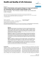
Fig. 1. (a) Polymer films with thicknesses of about 1 Am generated by
dipping a grid into polymer dispersions or solutions. The polymer films form
in grid meshes during evaporation of the water. (b) Water resistance
experiment: a grid with polymer films is placed between two glass slides
and immersed in water. Morphological changes can be monitored by light
microscopy.
First, three lab mortars containing a single polymer type
(latex, PVA, or CE) were analysed. In a second step, more
realistic mortars with two or all three polymer types were
investigated. In addition, different latices were used (formulation details see Table 1). This comparative study allowed
the development of characteristic morphological criteria for
the identification of the individual polymer types. The criteria
were used to detect different types of polymer films in real
mortars containing all three polymeric additives.
Based on standard EN1348, the mortars were applied in
two steps on a concrete plate (10 Â 40 Â 3 cm, Gehwegplatte,
Gebr. Mu¨ller AG, Triengen, Switzerland; water uptake is
approximately 3 wt.%): (1) A first contact layer with a
thickness corresponding to the coarsest grain size (approximately 0.3 mm) and (2) in a ripple and groove pattern
induced by a toothed trowel (teeth 6 Â 6 Â 6 mm) on top of the
first contact layer. After 5 min of air exposure (referred to as
Open Time), fully vitrified ceramic tiles (5 Â 5 Â 0.5 cm;
Winkelmanns weiss unglasiert lose, SABAG Bauhandel AG,
Rothenburg, Switzerland) were laid in. They were loaded
with 2 kg for 30 s, creating a 1 –2 mm thick continuous mortar
layer between concrete substrate and tile. A more detailed
description is available in Ref. [20]. After 28 days of dry
storage (23 -C and 50% relative humidity), the sample was
crushed, and a mortar fragment smaller than 3 mm was
sampled and studied in a Philips ESEM-FEG XL30 equipped
with a gaseous secondary electron detector and a Peltier
cooling stage. Polymer domains were located, imaged and
their coordinates were stored. By changing the sample
temperature and the water gas pressure, water condensed on
the sample, which was consequently wetted completely. After
30 min of water exposure, all water was evaporated by
changing temperature and pressure conditions. During the
whole experiment, the temperature was in the range of 1 –10
-C. The polymer domains were imaged again and qualitatively compared with the microstructures documented before
watering.
2.3. Quantitative scanning microscopy
Two specific methods were developed to quantify the
latex, CE, and PVA distribution within mortars with
81
compositions according to Table 1 and prepared as
described above. The visualisation and quantification of
the latex from the RP containing vinyl-acetate/ethylene/
vinyl-chloride (VC) was based on wavelength-dispersive
spectrometric (WDX) Cl mappings of a 1.5 mm wide
section in the centre of the mortar bed (electron microprobe
Cameca SX-50).
CE and PVA were stained with a fluorescent dye prior to
mortar mixing. Their occurrence in the mortar bed was
visualized with a laser scanning microscope (LSM) on
impregnated and polished sections across the half-length
mortar bed. In a second step, the spatial distributions of VC,
CE, and PVA were measured using quantitative image
analysis [20]. The polymer concentrations in horizontal
stripes were stacked to generate vertical concentration
profiles across the 1.1 –1.4 mm thick mortar bed. Due to
large differences in grain size between the coarse sand
fraction and the fines, which comprise the cement-polymer
matrix, the interstitial matrix phase is enriched at the
relatively flat interfaces to tile and substrate. In order to
avoid this geometric effect on calculations of distributions
within the matrix, and to investigate potential polymer
fractionations within the matrix, all its constituents are
normalised to the volume percentage of the cement-polymer
matrix. Following Ref. [21], we define the cement-polymer
matrix as the sum of all fines including cement phases, gel
pores (< 10 nm), capillary pores (10 nm – 10 Am), fine-grained
mineral filler, and all polymer phases. The mortar consists
therefore of air voids, sand grains, and the cement-polymer
Fig. 2. (a) A composite polymer film consisting of PVA and latex formed
from RP redispersed in deionised water. This structure is representative of
all investigated RPs. (b) Disintegration of composite film due to water
exposure. (c) Polymer film of the same redispersible powder, but
redispersed in filtered cement water. Only one polymer film is developed
that is water-resistant (d). Even after several weeks of water contact, only
minor morphological changes like swelling are visible.
A. Jenni et al. / Cement and Concrete Research 36 (2006) 79 – 90
deionised water
synthetic cement water
filtered cement water
NaOH (aq)
1
Latices
PVA
cellulose
ether
polyvinyl
alcohol
vinyl-acetate/
VeoVa
0
vinyl-acetate/
ethylene/
vinyl-chloride
The failure mode was examined macroscopically and
classified into adhesion failure (failure occurs between tile
and mortar), cohesion failure (failure occurs within the
mortar), or mixed failure, as described in Ref. [1].
Furthermore, SEM was used to study the fracture
morphology. For this purpose failure surfaces were coated
with a 300 nm thick carbon layer (Balzers carbon coater)
and examined in a CamScan CS4 SEM equipped with a
Robinson back-scattered electron (BSE) detector and a
Voyager 4 digital image acquisition system.
Polymer redispersed/dissolved in:
CaO (aq)
CaCl2 (aq)
2.5. Examination of failure surface
During water storage there is a significant loss in
adhesion strength. In order to understand the role of the
polymer during water contact, we performed model experiments where the behaviour of polymer films was microscopically investigated during water immersion (item 2.1).
Fig. 2a shows RP after film formation in deionised water.
The transparent PVA film in the centre is clearly distinguishable from the textured rim, as described in Ref. [24]. The
film identification is based on film morphology, which was
compared with monophase latex or PVA systems and was
also confirmed by element dispersive spectroscopy. During
water exposure, both phases disintegrated within minutes
(Fig. 2b). In contrast, a film formed from RP redispersed in
cement water (Fig. 2c) was water-resistant even after several
weeks of water immersion (Fig. 2d). Note that macroscopic
polymer films synthesised from deionised and cement water
behaved in a similar manner when exposed to water.
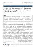
Different types of RP, CE, and PVA films produced from
redispersions/solutions made of deionised, synthetic cement,
and filtered cement water were rewetted by deionised water
(Fig. 3). All RP films showed a remarkable increase in water
resistance when produced from a redispersion made of
cement water instead of deionised water. In particular, a
large increase in water resistance of the EVA was observed
in the presence of cementitious ions. In general, RP films
made from filtered cement water were more water-resistant
than RP films made from synthetic cement water. NaOH
seems to have a more pronounced influence on water
resistance than Ca salts. In contrast, CE and PVA
redissolved instantaneously, independent of the composition
of the aqueous phase used for film synthesis.
To check for a potential influence of cement water (a
situation that is closer to a real wet stored mortar system), all
ethylene/
vinyl-acetate
The adhesive strength was measured by a standard
tensile test according to EN 1348. Shear strength and
flexibility were evaluated by a test in which, in contrast to
the tensile test, the deformation apparatus was run in
compressive mode pushing the ceramic tile (50 Â 50 mm),
which overlapped the substrate plate by 10 mm. Both,
applied force and shear displacement were continuously
monitored. In order to obtain the shear strength, the
measured force was divided by the mortar – tile contact
area (2000 mm2). This simple method provides information about both, shear strength and flexibility (shear stress
and deformation at break, respectively). Five strength tests
were performed on each sample and the mean value was
then calculated. Note that the mechanical properties of wet
stored samples were measured in the wet stage immediately after withdrawal from the water tank.
Alternating storage consists of dry –wet cycles including
7 days of dry storage (23 -C and 50% relative humidity) and
21 days of wet storage (completely immersed in water). The
tests described above were performed immediately after
each storage period.
Shrinkage and expansion were measured on 1 Â 4 Â 16
cm mortar prisms, which were demoulded after 24 h for a
zero reference measurement. The prisms were then stored
under dry or wet storage conditions and prism length was
measured at selected time intervals.
3.1. Model system
acrylic
2.4. Testing of mechanical properties
3. Results
styrene/
acrylic
matrix. As mortar components may be fractionated across the
mortar bed, the distribution patterns were depicted in crosssections perpendicular to the mortar bed and the trowelling
direction. An extended description of sample preparation,
image acquisition, analysis, and quantification of polymermodified mortars is available in [20]. The samples were
subjected either to dry storage (28 days at 23 -C and 50%
relative humidity) or wet storage (7 days at 23 -C and 50%
relative humidity + 21 days completely immersed in water,
followed by at least 28 days under room conditions before
impregnation). The obtained data provide the basis (a) for the
detection of various microstructure modifying processes
during wet storage, and (b) for a comparison between
microstructures and physical properties.
Water resistance
82
CE
Fig. 3. Qualitative observation of the water resistance of different polymers
synthesised from deionised, filtered, and synthetic cement water. Vertical
axis: 0 = virtually complete disintegration (shown in Fig. 2b), 1 = no changes
during water contact (shown in Fig. 2d).
A. Jenni et al. / Cement and Concrete Research 36 (2006) 79 – 90
films were also exposed to cement water. However, no
difference in polymer behaviour was observed with exposure to cement water, relative to deionised water.
3.2. In situ watering
To investigate the behaviour of polymers in a real mortar
exposed to water, mortar samples containing only one
polymer type were monitored before and after wetting
within the ESEM sample chamber (method description in
item 2.2, data in Fig. 4). The images represent typical
examples from an extensive image database.
The latex film depicted in Fig. 4a survives the wetting
period without major changes (Fig. 4b), and only the film
surface tends to change from a smooth to a more structured
morphology. In contrast, CE structures (arrows in Fig. 4c)
dissolve completely during wet storage (Fig. 4d). Fig. 4e
83
shows the base of an air void with no polymer microstructures. After water immersion, PVA films precipitated
out of the evaporating water (Fig. 4f), clearly indicating the
mobility of PVA.
These results are consistent with qualitative SEM
investigations on fractured mortar samples after water
storage. There, latex films are present and partly overgrown with cement hydrates, whereas the typical CE
membranes of dry stored mortars are absent after water
storage [25].
3.3. Distribution patterns before and after wet storage
By combining WDX, fluorescence microscopy and the
appropriate image analysis techniques, the spatial distributions of the polymer phases were determined. The comparison of the distribution diagrams before and after wet
Fig. 4. In situ polymeric microstructures in mortar before (left column) and after wetting experiment (right column) in the ESEM sample chamber. Each pair of
pictures shows the same location in the microstructure. VC latex film (a, b) and CE films (c, d). PVA structures could not be found in the mortar before wetting
(e), but PVA films form as the water front retreats during redrying (f).
84
A. Jenni et al. / Cement and Concrete Research 36 (2006) 79 – 90
dry stored equivalents. Mortars without CE were not
tested because they are not applicable as tile adhesives.
However, modification of the mortar with RP reduces the
strength decrease remarkably (Fig. 6a).
In addition, an alternating dry and wet storage were
applied to a mortar modified with RP (EVA) and CE.
Adhesive strength, flexibility and shear strength were
measured immediately at the end of each storage period.
In general, the adhesive strength increased with each new
dry– wet cycle (Fig. 6a). Fig. 6b shows the corresponding
flexibility and shear strength values. After the initial dry
storage, the following wet storage causes a decrease of both,
flexibility and shear strength. After the second dry storage
period, the flexibility recovers and reaches the value of the
initial sample, whereas the shear strength increases. In the
following wet –dry storage cycles shear strength increases
with each cycle. With respect to flexibility, a slight decrease
occurs with each cycle.
Fig. 6c shows the evolution of pore size distribution
(mercury intrusion porosimetry) and portlandite content
(measured according to Ref. [26]) as a function of the wet
storage duration. The total porosity decreases with
ongoing wet storage and the pore size distribution shifts
towards smaller pore sizes (gel pores). Simultaneously, the
portlandite content, which is an indicator for the degree of
hydration, increases (data taken from Ref. [35]).
Fig. 6d documents changes of the mortar volume during
wet and dry storage. Dry stored mortars shrink within the
first 7 days. The following wet storage induces a rapid
expansion during the first 2 days. Surprisingly, redrying of
this wet stored sample induces shrinkage that is twice as
intense as the initial drying shrinkage.
storage indicates what type of polymer is mobilised, to what
extent and in which direction.
Fig. 5 shows a representative VC latex distribution in the
cement-polymer matrix before (a) and after (b) wet storage.
The mortar bed is subdivided into layers parallel to the
mortar – tile interface and for each layer, the latex concentration in the cement-polymer matrix is depicted. Apparently,
there are no changes in latex concentration and distribution
during wet storage. To date, no methods exist to visualise and
quantify other latices within the microstructure.
Analogously, Fig. 5c and g show the CE distributions in
a VC-/CE-modified and a SA-/CE-modified dry stored
mortar, respectively. After wet storage, the corresponding
CE distributions are shown in Fig. 5d and h. Both wet
stored mortars show a pronounced CE increase from tile to
first contact layer. The enrichment at the contact layer
surface after dry storage increased significantly, and there
is also a significant enrichment directly above the
substrate.
The PVA distributions in the same two dry and wet
stored mortars are depicted in Fig. 5e, f, i, and j. In both
mortars, the PVA enrichment at the substrate surface is more
intense after wet storage. Otherwise, the distribution
patterns after dry and wet storage are identical for both
VC- and SA-modified mortars.
3.4. Mechanical properties
Dry and wet stored mortar samples were subjected to
adhesive strength tests to compare their mechanical
properties (Fig. 6a, first cycle). All wet stored samples
show a decrease in adhesive strength compared to their
VC-modified mortar
a)
c)
Latex
SA-modified mortar
e)
CE
g)
PVA
i)
CE
Tile
Tile
Tile
Tile
Substrate
Substrate
Substrate
Substrate
Substrate
Dry storage
Tile
0
1 2 3 4 5
Latex [vol.% in matrix]
b)
0.0
0.5
1.0
CE [vol.% in matrix]
d)
Latex
0.0
0.5
1.0
PVA [vol.% in matrix]
f)
CE
0.0
0.5
1.0
CE [vol.% in matrix]
h)
PVA
j)
CE
Tile
Tile
Tile
Substrate
Substrate
Substrate
Substrate
Substrate
Wet storage
Tile
1 2 3 4 5
Latex [vol.% in matrix]
0.0
0.5
1.0
CE [vol.% in matrix]
0.0
0.5
1.0
PVA [vol.% in matrix]
0.0
0.5
1.0
CE [vol.% in matrix]
Surface of
contact layer
0.0
0.5
1.0
PVA [vol.% in matrix]
Tile
0
PVA
PVA
Surface of
contact layer
0.0
0.5
1.0
PVA [vol.% in matrix]
Fig. 5. Quantitative distribution diagrams of VC latex, CE and PVA across the mortar bed for dry and wet stored samples.
A. Jenni et al. / Cement and Concrete Research 36 (2006) 79 – 90
Adhesive strength [N/mm2]
1.5
b)
dry
wet
Formulations
without latex
Alternating
storage
1.0
0.5
0.0
c)
1.cycle
CE
CE+
PVA
1.cycle
2.cycle
3.cycle
3.cycle
2.5
2.cycle
2
4.cycle
Initial
dry
sample
1.cycle
0.25
CE+EVA
(latex+PVA)
0.3
0.35
Flexibility [mm]
d)
Portlandite
0.0
30
20
4
10
2
28d dry
7d dry
7d wet
7d dry
21d wet
7d dry
42d wet
Total shrinkage [mm/m]
40
Portlandite [wt.%]
50
Porosity [vol.%]
4.cycle
3
1.5
1.cycle
Air voids
Capillary pores
Gel pores
0
dry
wet
3.5
Shear strength [N/mm2]
a)
85
0
0.5
Wet storage
1.0
1.5
Dry storage
2.0
Redrying
2.5
Dry storage
of 2.cycle
1.cycle
3.0
0
7
14
21
28
Time [days]
35
42
49
Fig. 6. (a) Adhesive strength of different mortar formulations (see Table 1). (b) Evolution of shear strength and deformation during four cycles of dry – wet
storage applied to the tile adhesive modified with CE and RP (EVA) measured in (a). (c) Pore size distribution and amount of portlandite after dry and wet
storage. (d) Shrinkage and expansion during dry and wet storage, and during redrying of a mortar prism.
3.5. Failure mode and related microstructures
Two types of failures can be distinguished: adhesion
failure occurs at the mortar – tile interface, whereas cohesion
failure is localised within the mortar bed. Comparing failure
modes after dry and wet storage indicates that dry storage
causes mixed failure (adhesive failure above ripples and
cohesive failure above grooves, see Fig. 11 in Ref. [1]),
whereas wet storage predominantly induces pure adhesion
failure. In this context, the mechanism of interfacial water
intrusion and the consequences for mineral growth is of
special interest. Therefore, the migration of the waterfront at
the mortar – tile interface was observed through a transparent
glass tile (Fig. 7a). The capillary waterfront can be
recognised as an abrupt change from bright (dry) to dark
grey (wet). In terms of water migration the following
observations were made by mapping the waterfront at
different times: (a) The migration rate of the water front
slows down in mortars with increasing amounts of latex,
and also depends on the latex hydrophobicity. (b) Water
intrusion in the mortar bed starts at the rim of the tile and
progresses continuously towards the centre. Additional
SEM investigations showed that in the rim regions, both
portlandite and ettringite are found, whereas ettringite
predominates towards the centre. This difference in mineralogy is attributed to the variable time interval during which
water is present at the rim and at the centre. Note that this
variation is found close to the tile –mortar interface as well
as in the mortar bed itself.
At the interface, ettringite grows in pores and in
shrinkage/expansion cracks, which opened during water
storage (Fig. 7c and d). Ettringite needles grown in these
cracks rarely touch the opposite crack side and therefore did
not induce cracking. Instead they rather seem to fill the
created cavity. It is important to note that these cracks do not
occur in dry stored mortars. No ettringite grows across
interfacial cracks, i.e., between mortar and tile. In contrast,
portlandite plates grow parallel and perpendicular to the
interface, and even grow onto the ceramic tile (Fig. 7e).
Phenolphthalein applied to the failure surface of a dry
stored mortar sample shows a carbonation front that
advanced from the grout (peripheral part of mortar bed)
towards the centre (Fig. 7b) [27].
4. Discussion
The mechanisms which occur from the time the fresh
mortar is mixed until hardening, and the resulting microstructures are extensively discussed in Ref. [1]. One of the
major findings was that the migrating pore water causes CE
and PVA to segregate across the mortar bed. The resulting
86
A. Jenni et al. / Cement and Concrete Research 36 (2006) 79 – 90
Fig. 7. Microstructures at the mortar – tile interface. (a) Glass tiles allow tracing of the intruding water front. Situation after 2 days of water immersion. (b)
Phenolphthalein applied to mortar bed of dry stored mortar after tearing off the tile. (c, d) SEM images: Ettringite (E), micro-cracks (C), and portlandite (P)
on the failure surface of a wet stored VC-modified mortar. (e) Tile part of the mortar – tile interface after adhesive strength test, opposite side from sample
shown in c).
microstructural heterogeneities have a major influence on
type of failure mode and bulk strength. As water intrusion
during wet storage also induces water fluxes, further phase
migrations can be expected. In the following, we focus on
the relationship between microstructural changes and related
physical properties of tile adhesives during water immersion. The mechanisms detected are valid for the chosen
mortar formulation and sample configuration (e.g., material
and dimensions of substrate and tile), and may change for
deviating set-ups. Three major topics are discussed: (1) the
mobility of pore water and polymers, (2) volumetric
changes, and (3) reinitiated hydration of the cement.
4.1. Influence of water intrusion and related mobilisation of
polymers on mechanical properties
Because of the interconnected pore network, water
intrusion during wet storage is a 3D-problem. Based on
sections parallel and perpendicular to the tile –mortar –
substrate interfaces (Figs. 5 and 7), we can detect the 3D
water flow and study the related microstructural changes. In
top view, the water front moves from the grout towards the
centre of the mortar bed (Fig. 7a). Perpendicular to the
mortar bed, the water usually first intrudes the mortar, and
from there the underlying concrete plate, creating a water
flux through the mortar towards the substrate. The more
hydrophobic the redispersible powder is, and the higher its
quantity, the lower the intrusion rate. As the polymers seal
the pores, they reduce the degree of connectivity of the
pores and also the intrusion rate. Such pore structure
alterations also result in a reduced carbonation depth prior
to water immersion (Fig. 7b). Ohama [21] has already
demonstrated that latex-modification decreases the total
porosity and the carbonation depth.
In the case of wet storage, questions about the behaviour
of the polymers during water exposure arise. The water
resistance depends on the latex type: Beeldens [18]
measured a good water resistance of macroscopic polymer
films made from dispersions without cement ions (polymer
types: styrene acrylic acid ester, carboxylated styrene–
butadiene, acrylic emulsion, styrene – acrylic emulsion,
styrene –butadiene, vinyl co-polymers). In the present study,
model experiments and ESEM investigations under wet
conditions show a significant difference in water resistance
between latex and solution polymers (CE and PVA; Figs. 3
and 4). Water dissolves CE and PVA films immediately,
independent of the initial ion concentration of the polymer
solution. In contrast, all tested latices show an increased
water resistance if cementitious ions were present during
film formation. In case of the EVA powder, enhanced water
resistance in the presence of sodium ions suggests a close
relationship between film properties and type of ion.
All investigated dispersions and redispersible powders
contain PVA, which is assumed to form the shell of the latex
particles or even exists as an interstitial phase between them.
According to Ref. [28], saponification generally is enhanced
by a higher alkali (Na+ and K+) concentration. Transferred
to our system, saponification of PVA is promoted by the
A. Jenni et al. / Cement and Concrete Research 36 (2006) 79 – 90
sodium hydroxide. This hydrolysed PVA is supposed to
hinder latex interdiffusion to a smaller extent. Consequently,
sodium hydroxide favours coalescence of latex particles
resulting in an increase in water resistance. This assumption
is in agreement with findings of Chevalier et al. [29].
Du Chesne et al. [30] describe the addition of ionic
surfactants to improve the water resistance of latex films. In
this case, interaction with the surfactant leads to imperfect
PVA membranes that are no longer able to prevent latex
interdiffusion (coalescence). Presumably, cementitious ions
might have a similar effect leading to PVA accumulations in
interstitial pools and PVA immobilisation. In this context,
different ions might play different roles. While alkali and
hydroxyl ions increase the degree of hydrolysis of the PVA,
which in turn reduces its cold water solubility, divalent
cations may cause a bridging of the accumulated PVA
polymers.
Beside these inferences about the mechanisms that
improve latex interdiffusion, we have microscopic evidence
that the degree of film formation is more advanced in
cementitious systems. The SEM morphology study [24]
revealed that the surfaces of latex films made from a
cementitious redispersion are smoother, while latex films
made from deionised water redispersions predominantly
show particle structures. According to Ref. [31] the film
surface flattens with advanced film formation. Therefore, we
interpret the reduced film relief as a progressed stage of film
formation of these ‘‘cementitious’’ latex films. Latex films in
real mortars rarely show relicts of the initial particle
structure (Fig. 4 a and b; [1]). This suggests that latex film
formation in mortars usually reaches the final stage of
coalescence, which is also concluded in Ref. [18].
In the case of acrylic co-polymers, divalent calcium
ions might induce an additional mechanism to increase
water resistance, called cross-linking [2,32]. Because
carboxylate groups can also link onto cationic sites on
mineral surfaces, this involves a latex – cement interaction
87
mechanism. Often, such interactions occur too early in
the fresh mortar stage and cause coagulation and bad
workability properties, which in turn reduce proper
wetting of the tiles and, thus, lower final adhesion
properties.
Because latex structures in mortars are water-resistant,
they are also immobile during water storage. This is
confirmed in Fig. 5a and b where a homogeneous latex
distribution after dry and wet storage are shown.
In contrast, CE and PVA films in the mortar dissolve
during water exposure (Fig. 4c to f). Although the
distribution patterns of CE prior to water immersion in
mortars with different latices (VC versus SA) vary due to
the different CE – latex interaction mechanisms [1], water
intrusion changes the CE distribution in both mortars in a
similar way and via the same mechanism (Fig. 5c, d, g,
and h). Water intrusion from the grout induces water
migration through the mortar bed towards the underlying
concrete substrate. Simultaneously, the dissolved CE is
transported downwards through the capillary pores, but
accumulates at the contact layer and substrate surface,
which act as micro-filters (Fig. 5 d and h). This filtering
is interpreted to result from a locally reduced pore size.
The pore size reduction at the upper horizon (top of
contact layer within the mortar bed) results from
trowelling by the tool whereby this temporary surface is
smoothed and superficial pores are closed [1]. Fig. 8a
illustrates an example of reduced porosity at the surface
of the mortar versus the internal porosity (inset). The local
porosity is further reduced by the CE enrichments at
surfaces. This can be seen by comparing the frames in
Fig. 8a and b. The filtering effect at the mortar – substrate
interface can be explained by a drastic change in porosity
between the high-porous mortar and the dense concrete
substrate. The carbonated surface of the concrete plate
also helps to reduce the porosity. The few CE occurrences
found in the substrate are all located in micro-cracks.
Fig. 8. (a) SEM secondary electron image of the uncovered mortar surface that underwent skinning (dry stored, EVA-modified mortar). The inset (same scale)
shows the microstructure of a cohesive failure across the cement-polymer matrix. (b) The same mortar surface as in a) in back-scattered electron mode where
polymers become transparent and only mineral structures are visible. Compare the boxes in a) and b).
88
A. Jenni et al. / Cement and Concrete Research 36 (2006) 79 – 90
Although exactly the same segregation mechanisms as
described above can be expected for PVA, the water flux
during wet storage stage influences the PVA distribution to a
much lower extent. This can be attributed to the reduced
cold water solubility of a fully hydrolysed PVA, and to the
fact that the smaller polymer size allows PVA to occur in
smaller capillary pores. As a consequence, PVA is intergrown with cement hydrates on a smaller scale.
Even though redispersible powders increase tensile
adhesion strength after both dry and wet storage, there is
a significant loss in wet strength (difference between dry
and wet strength in Fig. 6a). The same is observed for
adhesive shear strength and flexibility (Fig. 6b). In spite of
these reductions, however, further drying of the samples
yields the same or even higher strengths than those of the
initial sample. This reversible behaviour can be explained
by water uptake and softening of the latex microstructures
during water immersion followed by redrying and related
strengthening of the same microstructures. Enhanced latex
interdiffusion in a swollen stage of latex during water
immersion, resulting in an increased coalescence of the
latex film, represents an explanation for the overstepping
in strength compared to the initial dry stored sample
(compare Ref. [33]). Additional effects of water storage
and their influence on the mortar strength are discussed
below.
4.2. Volume changes and mechanical properties
Physical shrinkage and expansion depend mainly on the
porosity, environmental conditions (humidity, e.g., Ref.
[12]), and geometric aspects like body dimensions and
restraining conditions of juxtaposed materials (tile, concrete
substrate, grout). Stress gradients induced by these parameters can occur throughout the mortar layer, which may
result in failure, and can therefore be critical. There is little
known about the mutual interaction of all these parameters
and the resulting internal stresses. In the following section,
we will highlight some major findings of the shrinkage/
expansion behaviour of tile adhesives.
The w / c of concretes is widely known to be a major
factor for drying shrinkage. The higher the w / c, the higher
is the capillary porosity, which enhances capillary drying
shrinkage. Tile adhesives have a w / c around 0.8 and these
mortars are only partly hydrated. Drying shrinkage for dense
concrete and high-porous tile adhesive mortars falls within
the same range of 1 –2 mm/m [11,10]. This indicates that in
case of tile adhesive mortars, a major part of drying
shrinkage must be accommodated by so-called inner
shrinkage (increasing bulk porosity including shrinkage
cracks). During water storage of a previously dry-cured
mortar, volume changes due to water intrusion and the
reinitiated secondary cement hydration can induce cracking
(Fig. 7c). The situation can be particularly critical with
respect to adhesion strength at the tile –mortar interface,
where the highest material contrasts occur.
Of special interest are the irreversible volume changes
occurring during alternating dry – wet storage cycles (Fig.
6d). For concrete it is often described that the irreversible
part of the initial drying shrinkage increases with higher
porosity (e.g., Ref. [11]). In our mortar system, however,
we face a different situation of repeated, additional and
irreversible drying shrinkage. In case of redrying of wet
stored mortars, drying shrinkage can be twice as intense as
the expansion during the previous period of water storage.
We interpret this behaviour as a consequence of the
secondary cement hydration during water immersion. This
is confirmed by the fact that both the irreversible drying
shrinkage component and the degree of secondary cement
hydration, are progressing at similar rates, and terminate as
the mortar is close to complete hydration after 5 dry – wet
cycles [34]. The link between these two phenomena is
interpreted to be the pore size distribution. Air voids,
capillary and gel pores change their relative and absolute
quantities during ongoing hydration and cause a general
shift of pore size distribution towards smaller pores (Fig.
6c). Drying shrinkage is generated by retreating water
films along the walls of capillary and gel pores. In this
way, the negative capillary pressure causes the cement
matrix to shrink (e.g., Ref. [12]). With an increasing
number of small-sized pores, the area of pore walls
increases as well, lowering the total capillary pressure in
the system during retreat of the water films. Consequently,
a more intense volume decrease occurs during redrying
(Fig. 6d). The reason for the increased irreversible
shrinkage during redrying is thus based on the initial
low degree of hydration.
Comparing the highly porous mortar, the dense concrete
and the ceramic tile, the most pronounced difference in
volumetric changes during water intrusion and drying will
occur at the mortar –tile interface. As this interface is
progressively wetted and dried from rim to centre (Fig. 7a),
the lateral variations in volume changes create strong
gradients along the interface promoting crack formation.
This is a potential explanation for the commonly observed
failure localisation at the mortar – tile interface in wet stored
mortars.
4.3. Influence of hydration on mechanical properties
As indicated by a strong and progressive increase in the
amount of portlandite and gel pores (Fig. 6c), cement
hydration, which virtually stopped after 7 days of dry
storage, continues during wet storage. Besides polymer film
formation, cement hydration is the other major strengthening mechanism. Particularly during water storage when the
solution polymers dissolve and the latex films swell and
soften, the degree of cement hydration dominates the bulk
strength of the mortar. The reinitiated hydration during
water immersion is the main reason for an enhanced dry and
wet strength with further storage cycles (Fig. 6a and b). As
this secondary hydration is considered to create rigid
A. Jenni et al. / Cement and Concrete Research 36 (2006) 79 – 90
mineral structures, the flexibility, mainly given by latex, is
constant or decreases slightly.
The aspect of hydration at the mortar– tile interface is of
special interest, because this is the site of failure after wet
storage. Fig. 7c to e are typical examples of portlandite
crystals, which grew during water storage in cracks at the
mortar –tile interface caused by differential volume changes.
Because such relatively large portlandite crystals can hinder
the reversible opening and closing of cracks during dry –wet
cycling, they may induce stress concentration, promoting
further crack propagation along the mortar – tile interface
during the closing phase (shrinkage during drying). Crystallisation pressure of portlandite might represent an
alternative explanation for interfacial cracking and related
adhesion failure.
5. Conclusions
In light of polymer film formation, the chemical environment plays a crucial role controlling the final film properties.
This is particularly important for experimental simulations of
polymer film formation in cementitious systems. In this way,
model experiments involving film formation on grids are
only realistic when performed under similar chemical
conditions (ionic concentration) as present in the mortar. It
is important to note that additional parameters like mineral
intergrowth do not influence the overall water resistance of
the films. Therefore, this type of model experiment represents
a fast and easy screening test for the water resistance of
polymer films in cementitious environments.
Microstructural changes during wet storage and resulting
material properties of tile adhesives can be divided into two
principal groups: (a) irreversible changes, and (b) reversible
changes.
a) Irreversible changes are mainly related to the low
degree of initial cement hydration after dry storage. As the
cement continues to hydrate during water immersion, the
cement-derived strength component increases. Simultaneously, this secondary hydration during wet storage shifts the
pore size distribution towards smaller pore sizes, a process
that increases drying shrinkage during the following
redrying. In terms of adhesion strength, this additional
component of drying shrinkage can be critical, because
cracks preferentially form at the mortar – tile interface,
where the material contrast is most pronounced. The
formation of large portlandite crystals in these cracks is
thought to further reduce strength.
Once formed in the cementitious environment, the latex
films at least partly reach the coalescence stage, which
provides their water resistance. During water immersion,
latex interdiffusion can be reactivated promoting further
coalescence. This improves the mortar properties after
redrying. As a consequence of its immobility, latex cannot
enter the newly formed shrinkage cracks to heal these
microdefects.
89
Solution polymers, like CE and PVA, do not form waterresistant microstructures, and have therefore no influence on
strength in the wet stage. They redissolve during each water
immersion period, are transported by the migrating pore
water phase and enriched due to filtering mechanisms. As
PVA is fully hydrolysed with time, its solubility is
decreased, which lowers the PVA mobility compared to CE.
b) Reversible changes during water storage can be
followed in test series over multiple dry – wet cycles.
Adhesion strength and flexibility are lost and regained as
the sample is wetted and dried, respectively. This can be
related mainly to reversible swelling and softening, followed
by drying and strengthening of the latex films in the mortar.
Shrinkage and expansion are also partly reversible. As RP
enhances the flexibility of the bulk system, latex is thought
to increase this reversible part of the volume changes.
This study demonstrates that the interplay of all
endogenous (mortar components) and exogenous (environmental) parameters determines the evolution of the microstructure and therefore the material properties of polymermodified mortars during wet storage. The relationships of
the various interaction mechanisms have to be taken into
account for future research and product development.
Acknowledgements
Financial support from KTI for project Nr. 4551.1 KTS is
gratefully acknowledged. We would like to thank Dominique Schaub, Verena Jakob and Ju¨rg Megert for the
elaborate sample preparation. Robert Koelliker, Karl Ramseyer and Adrian Pfiffner are acknowledged for valuable
discussion. The electron microprobe used was financed by
the Swiss National Science Foundation (Credit 2126579.89). We greatly acknowledge Hans Imboden for
giving us access to the LSM of the Institute of Cell Biology
(University of Berne).
References
[1] A. Jenni, L. Holzer, R. Zurbriggen, M. Herwegh, Influence of
polymers on microstructure and adhesive strength of cementitious tile
adhesive mortars, Cement and Concrete Research 35 (2005) 35 – 50.
[2] Y. Ohama, Handbook of Polymer-Modified Concrete and Mortars,
Properties and Process Technology, Noyes Publications, Park Ridge,
NJ, USA, 1995.
[3] H. Ball, M. Wackers, Long-term durability of naturally aged
GFRC mixes containing Forton polymer, Proc. GRC congress,
Concrete Society, Dublin, 2001, pp. 83 – 97.
[4] J. Schulze, Influence of water – cement ratio and cement content on the
properties of polymer-modified mortars, Cement and Concrete
Research 29 (1999) 909 – 915.
[5] J. Schulze, O. Killermann, Long-term performance of redispersible
powders in mortars, Cement and Concrete Research 31 (2001)
357 – 362.
[6] K. Tubbesing, Mikrostruktur von PCC : Gefu¨geuntersuchungen an
polymermodifizierten Zementsteinen, PhD thesis, Technische Universita¨t Hamburg – Harburg, Hamburg, 1993.
90
A. Jenni et al. / Cement and Concrete Research 36 (2006) 79 – 90
[7] Z. Su, Microstructure of polymer cement concrete, PhD thesis,
Material Sciences Group, Delft University of Technology, Delft,
Netherlands, 1995.
[8] R.A. Cook, K.C. Hover, Mercury porosimetry of hardened cement
pastes, Cement and Concrete Research 29 (1999) 933 – 943.
[9] D.A. Silva, V.M. John, J.L.D. Ribeiro, H.R. Roman, Pore size
distribution of hydrated cement pastes modified with polymers,
Cement and Concrete Research 31 (2001) 1177 – 1184.
[10] A. Dimmig, Einflu¨sse von Polymeren auf die Mikrostruktur und die
Dauerhaftigkeit kunststoffmodifizierter Mo¨rtel (PCC), PhD thesis,
Bauhaus-Universita¨t, Weimar, 2002.
[11] K. Krenkler, Chemie des Bauwesens, Springer Verlag, Berlin, 1980.
[12] J. Stark, B. Wicht, Zement und Kalk: der Baustoff als Werkstoff,
Birkha¨user, Basel, 2000.
[13] P.T.H.G. Lunk, Kapillares Eindringen von Wasser und Salzlo¨sungen in
Beton, PhD thesis, ETH, Zu¨rich, 1997.
[14] E.A.B. Koenders, Simulation of volume changes in hardening cementbased materials, PhD thesis, Technische Universiteit Delft, Delft,
Netherlands, 1997.
[15] Z. Lu, X. Zhou, The waterproofing characteristics of polymer sodium
carboxymethyl-cellulose, Cement and Concrete Research 30 (2000)
227 – 231.
[16] H. Justnes, T. Reynaers, W. Van Zundert, Dimensional changes of
polymer cement mortars based on latices and redispersible polymer
powders due to moisture transport, Proc. Adhesion between Polymers
and Concrete, 2nd International RILEM Symposium ISAP ’99, vol.
PRO 9, Cachan Cedex, France, 1999, pp. 475 – 483.
[17] J. Bijen, E. Schlangen, T. Salet, Modelling of effects of shrinkage on
the performance of adhesives, Proc. Adhesion between Polymers and
Concrete, 2nd International RILEM Symposium ISAP ’99, vol. PRO
9, Cachan Cedex, France, 1999, pp. 299 – 310.
[18] A. Beeldens, Influence of polymer modification on the behaviour of
concrete under severe conditions, PhD thesis, Katholieke Universiteit
Leuven, Heverlee, Belgium, 2002.
¨ ber die Zusammensetzung der
[19] I. Odler, E.N. Strassinopoulus, U
Porenflu¨ssigkeit hydratisierter Zementpasten, TZI-Fachberichte 106
(6) (1982) 394 – 401.
[20] A. Jenni, M. Herwegh, R. Zurbriggen, T. Aberle, L. Holzer,
Quantitative microstructure analysis of polymer-modified mortars,
Journal of Microscopy 212 (2) (2003) 186 – 196.
[21] Y. Ohama, Principle of latex modification and some typical properties
of latex-modified mortars and concretes, ACI Materials Journal 84 (6)
(1987) 511 – 518.
[24] A. Jenni, M. Herwegh, R. Zurbriggen, L. Holzer, Polymerverfilmung
in zementa¨ren Systemen, Proc. 3. Tagung Bauchemie, vol. 24, GDChFachgruppe Bauchemie, Wu¨rzburg, 2001, pp. 92 – 97.
[25] A. Jenni, M. Herwegh, R. Zurbriggen, Morphologie und Innenleben
von Polymer-Phasen in Zementmo¨rteln, Proc. Tagung Bauchemie,
Weimar, 2002.
[26] B. Franke, Bestimmung von Calciumoxid und Calciumhydroxid
nebem wasserfreiem und wasserhaltigem Calciumsilicat, Zeitschrift
fu¨r anorganische und allgemeine Chemie 241 (1941) 180 – 184.
[27] RILEM Committee CPC-18, Measurement of hardened concrete
carbonation depth, Materials Structure 18 (1988) 453 – 455.
[28] J.A. Larbi, J.M.J.M. Bijen, Interaction of polymers with portland
cement during hydration: a study of the chemistry of the pore solution
of polymer-modified cement systems, Cement and Concrete Research
20 (1990) 139 – 147.
[29] Y. Chevalier, C. Pichot, C. Graillat, M. Joanicot, K. Wong, J. Maquet,
O. Lindner, B. Cabane, Film formation with latex particles, Colloid
and Polymer Science 270 (1992) 806 – 821.
[30] A. Du Chesne, A. Bojkova, J. Gapinski, D. Seip, P. Fischer, Film
formation and redispersion of waterborne latex coatings, Journal of
Colloid and Interface Science 224 (2000) 91 – 98.
[31] F. Huijs, J. Lang, Morphology and film formation of poly(butyl
methacrylate)-polypyrrole core-shell latex particle, Colloid and Polymer Science 278 (2000) 746 – 756.
[32] S. Chandra, P. Flodin, Interactions of polymers and organic admixtures
on portland cement hydration, Cement and Concrete Research 17
(1987) 875 – 890.
[33] N. Jain, Influence of Spray Drying onto Powder Performance, Elotex
AG, Sempach Station, Switzerland, 2002.
[34] R. Zurbriggen, D. Schaub, Flexibilita¨t, Scherfestigkeit, Schwund,
Hydratationsgrad und Porenverteilung nach 10 Trocken/Nass-Zyklen,
Elotex AG, Sempach Station, Switzerland, 2000.
[35] D. Kno¨fel, D. Stephan, R. Zurbriggen, Hydratationsverhalten polymermodifizierter Mo¨rtel, Elotex AG, Sempach Station, Switzerland,
1988.