LoRa communications in wireless sensor network for radioactive sources monitoring system
Bạn đang xem bản rút gọn của tài liệu. Xem và tải ngay bản đầy đủ của tài liệu tại đây (429.3 KB, 6 trang )
Journal of Science & Technology 136 (2019) 060-065
LoRa Communications in Wireless Sensor Network for Radioactive
Sources Monitoring System
Vinh Tran-Quang*, Kieu-Ha Phung,
Kien Hoang Trung, Dung Mai Van, Dao Quang Thuan
Hanoi University of Science and Technology – No. 1, Dai Co Viet Str., Hai Ba Trung, Ha Noi, Viet Nam
Received: May 03, 2019; Accepted: June 24, 2019
Abstract
Using LoRa, a low-power long-distance communication technology, for wireless sensor networks (WSNs)
that have limited coverage range can extend to kilometers, much longer than other technologies such as
Zigbee, WiFi, WiSUN, while maintaining the sensor node's energy consumption at a relatively low level. In
this paper, the authors present the architecture of wireless sensor network systems used to monitor radiation
sources. The system consists of sensor nodes integrated with radioactive sensors and linked together to
form a radioactive network monitoring system. The LORA is used to transmit data between sensor nodes
and sink. Also in this paper, authors propose to use the MAC multi-access protocol specifically designed for
communication between nodes in the radiation control system, ensuring reliable transmission requirements
and advantages of energy consumption for communication function. Experimental implementation results
show that the system can work well with transmission range of up to 2 km in urban environments.
Keywords: radioactive sources monitoring, MAC, LoRa communications, wireless sensor network.
and treat such radioactive sources, an IoT system is
required. According to some reference models for
IoT, the communications in IoT as well as the
communications in wireless sensor networks (WSNs)
requires a signi cant expansion in the number of
connected devices. In response to this demand, sensor
nodes is technically required low cost, low power
consumption, and have the ability to connect through
wireless
communication
technologies
with
appropriate transmission distance [7]–[9].
1. Introduction
Radioactive* material out of the regulatory
control are radioactive sources, nuclear materials,
nuclear equipments that are lost, appropriated,
abandoned, illegally transferred, undeclared [1]. The
2004 Code of Conduct on the Safety and Security of
Radioactive Sources [2] requires countries to set up
mechanisms to restore radioactive sources that out of
regulatory control (Target number 5 of the Code).
Under the general principles of the Code, each
country must have a technical system to control the
stolen, abandoned radioactive sources as well as to
eliminate or minimize the consequences caused by
these sources of radiation [3][4].
Popular communication technologies such as
Bluetooth and WiFi are being used on a daily basis by
many devices like smartphones, laptops, and tablets
with high bandwidth but with a very shot
communication distance and high power consumption
have proved to be unsuitable for IoT or WSN
systems. Some other communication technologies
such as Zigbee [10] have low power consumption but
the transmission distance is still limited. LoRa
Technology (Long Range) [11] addresses the
weaknesses of these above technologies with a
theoretical straight line of sight transmission distance
up to 20 km in non-urban environment and from 2 km
to 5 km in urban environment. LoRa has the
maximum bandwidth of only 50 Kbps, but it is
suitable for IoT applications which do not require
high bandwidth. LoRa’s power consumption is quite
low (36 mA at maximum output power with Semtech
Module SX1272) [12]. In addition to LoRa long
distance communication and low power consumption
advantages, we found that this is a technology that
In spite of the management of the usage of
radioactive sources, they are still frequently using in
the world, increasing the risk of radiation exposure
for the population and the environment as well as the
impact on the socio-economic development. The
majority of known stolen sources are sources which
used in radiography, sources from isotopes, and
sources in industrial irradiation. Lost radioactive
sources are usually sealed sources, manufactured in
the form of bars, metal ball and their metal
containers. Therefore, when the radioactive sources is
lost, it usually being sold to the scrap metal recycling
facilities for recycling [3], [5], [6]. In order to detect
*
Corresponding author: Tel.: (+84) 912.636.939
Email:
60
Journal of Science & Technology 136 (2019) 060-065
satisfy the requirements of the Radioactive sources
monitoring system.
distance and the data rate. If large SF is selected, the
transmission distance will be long but the data rate is
lower.
In this study, the authors implement the LoRa
technology, namely LoRa SX1278 (Semtech) chip to
design and manufacture a low power consumption
communication module integrated with the wireless
sensor devices. The authors also propose a
startopology communication model which requires
multiple access in the radio sources. Therefore, we
propose a MAC-based multiple access protocol
applying the LoRa physical layer modulation
technology based on the ALOHA multiple access
protocol. Later we deployed the hardware system
integrating the protocol that we have proposed and
evaluated the stability, packet loss rate, and radio
resource utilization.
2.2. Bandwidth
LoRa uses three bandwidth values: 125 KHz,
250 KHz, 500 KHz. The receiver will send the data
that has been chipped as the same rate as the
bandwidth of the system. For example, if the system
has a bandwidth of 500 KHz, the chip rate is 500
Kcps. Error! Reference source not found.
illustrates the relationship between data rate,
spreading factor and receiver sensitivity.
Table 1. Relationship between DR, SF, and receiver
sensitivity.
DR
SF
DR0
DR1
DR2
DR3
DR4
DR5
12
11
10
9
8
7
2. LoRa Technology
LoRa is an ISM band wireless communication
technology. LoRa modulation uses Spectrum Spread
Chirp technique which is a small subset of DSSS
(Direct Sequence Spread Spectrum). This modulation
technique help to increase the link budget as well as
impove the network interface resistance [10]. LoRa
has three options of broadbands such as 125 KHz,
250 KHz, 500 KHz. This feature allows to increase
the ability of resisting channel noise, long term
relative frequency, Doppler effect and fading.
Extending a narrowband signal based on a wider band
reduces the use of spectrum. However, end devices
use and/or orthogonal sequences with different
channels resulting in higher overall system capacity.
Bit Rate
(kbps)
0.25
0.44
0.98
1.7
3.1
5.4
Sensitivity
(dBm)
-137
-135
-133
-130
-129
-124
2.3. Coding Rate
LoRa supports FEC (Forward Error Correction)
at receiver side as well as increases the sensitivity of
the receiver [10]. The Coding Rate (CR) has an
integer value from 0 to 4, with CR = 0 mean no FEC.
With different CR values, the number of bits added is
different and therefore the data rate is different.
Adding FEC improves the error correction but
reduces the data rate transmission.
Recently, various of research work has been
published in the topic of LoRa technology, ranging
from the fundamentals of LoRa modulation scheme
and technical comparison of LoRa with other wireless
technologies [10], to evaluation and investigation of
LoRaWAN, the proposal of LoRa Alliance about the
architecture and operation of LoRa-based networks
[13],[14]. LoRaWAN has proposed different
operation scheme for LoRa-based end devices/ sensor
nodes. The author of the work [15] has proposed a
mathematical model and simulation evaluation for
estimating the collision and packet loss of LoRaWAN
network in different scenarios of IoT applications.
3.
Radiation Source Monitoring System
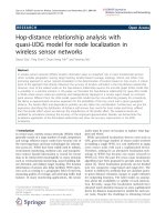
3.1. Radiation monitoring system architecture
The monitoring system of out-of-control
radioactive sources includes the following modules
(Fig. 1):
Sensing and Data Processing subsystem: includes
sensors for measuring radioactivity and other environment
physical parameters, like temperature, humidity, etc.
Communication
subsystem:
includes
the
communication modules on monitoring devices and
gateway which all build up a star-topology wireless
sensor network. Monitoring devices deliver data to the
gateway through the LoRa radio and the gateway
transfers the data to the data server by 2,5G/3G or
WiFi.
In the following sections, we present three main
features that define the distinction of the LoRa
modulation technique.
2.1. Spreading Factor
Because the LoRa modulation technique is
based on the Chirp spectral spreading modulation
technique in which the spreading factor, ranging from
SF7 to SF12, is an essential parameter. Selecting the
SF creates a trade-off between the transmission
Storage subsystem: responsible for data collection
and storage (data server), data processing.
61
Journal of Science & Technology 136 (2019) 060-065
Users can con gure the system, e.g. setup monitoring
period, warning thresholds, ect.
Monitoring
and
controlling
subsystem:
responsible for displaying visually the monitoring
data on the mobile application and web application.
Fig. 1. The radioactive sources monitoring system.
authenticate the joining requests from nodes and to
synchronize the monitoring nodes regularly.
3.4. Communication Protocols
The network of monitoring nodes is con gured
in star topology due to the long range capability of
LoRa technology. The monitor nodes will send the
data to the common gateway, the data collection
node. The gateway will aggregate data from the
monitoring nodes and then forward to the server via
the 2,5G/3G mobile communications.
The overall objectives of the system is to ensure
the real-time monitoring requirements while
maintaining low energy consumption at monitoring
nodes. Therefore, the communication sessions of
monitor nodes need to be well-controlled
to
minimize collision probability for reliable and low
latency data transmissions. Besides, the procedure of
authentication and node association into the network
should be designed. In the following part, we
describe in detail the design of communication
procedure in the monitoring devices and the gateway.
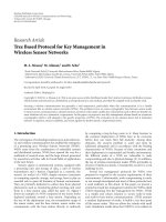
Fig. 2. The radioactive sources monitoring system
function and architecture.
3.2. Monitoring Node Architecture
The functional elements of a monitor node are
shown in Fig. 2. The node is equipped with
specialized sensors that measure gamma radiation,
neutrons, and other environment physical parameters.
The sensed data is transferred to the central control
unit for data processing, analyzing, and packaging to
be sent to LoRa communication module. The LoRa
SX1278 Chip is selected.
3.4.1. Message Formats
In this section, we discuss message structure of the
proposed protocol which includes multiple different
messages (Illustrated in Fig. 3(a), Fig. 3(b) and Fig. 3(c):
Joining Network Request message (msgJoinReq):
is generated by monitoring nodes, and sent to the
Gateway to request to participation into the network
before transmitting data message.
3.3. Gateway Architecture
In addition to the LoRa module, the gateway is
integrated with GSM LEON G100 module. Data
message received at the gateway will be processed
and then forwarded to the server through the this
module. Besides, the gateway is responsible to
Joining
Network
Response
message
(msgJoinRes): is created by gateway to response to
the Joining Network Request.
62
Journal of Science & Technology 136 (2019) 060-065
6:
7:
8:
9:
10:
11:
12:
13:
14:
15:
Data message (msgData): contains sensing data
which sent from monitoring nodes to the gateway.
Time Synchronization message (msgTimeSyn): is
utilized to synchronize system time which sent from
nodes.
Time
synchronization
Response
Message
(msgTimeSynRes): is generated by the Gateway to
response to the msgTimeSyn.
ACK Message (msgACK): is generated by the
Gateway to acknowledge the data reception.
Preamble
dst
1 byte
PHDR
PHDR_CRC
PHY Payload
src
packnum
length
@Rsanslab
retry
1 byte
1 byte
9 bytes
1 byte
(a)
Preamble
PHDR
PHDR_CRC
PHY Payload
( ) ==
then
success
( ) until new message
else
++
>
then
abort
else
← 0; 2
1
wait ×
with:
=2× + ;
: processing time at gateway;
: propagation time
goto step 2
end if
end if
if
16:
17:
18:
19:
esle
20:
goto step 2
21:
end if
22: end function
CRC
1 byte
if (
CRC
Algorithm 2 Receiving and Processing Data
dst
src
@BLxx
packnum
IMEI
length
SensorData
command
SystemTime
retry
1:
← authentification command
2: Gateway self-configure, setup parameters: DR, SF,
BW
3: while 1 do
4:
()
5:
if Receive packet then
6:
←
_
7:
if
is data message then
8:
←
.
9:
if correct authentification then
10:
if correct CRC then
11:
push data to buffer
and wait to forward
12:
send ACK to src-node
13:
else
14:
abort
15:
end if
16:
else
17:
abort
18:
end if
19:
else if
is joining network request then
20:
←
.
21:
←
.
22:
←
23:
if
≠
then
24:
←
25:
end if
26:
send joining network response to node
27:
else
28:
abort message
29:
end if
30:
end if
31: end while
Data
(b)
Preamble
dst
PHDR
src
PHDR_CRC
packnum
yy
length
mm
PHY Payload
TimeStamp
dd
hh
mm
CRC
retry
ss
(c)
Fig. 3. (a) Joining Network Message Format. (b) Data
message Format. (c) Time-synchronized message
Format
3.4.2. Random Multiple Access Protocol
We apply a multiple access protocol based on
the Aloha scheme. When a node need to transmit a
data message, the node will proceed to send that
message on the radio channel immediately, and then
wait for the ACK message in an approximate roundtrip time (RTT). RTT depends on the propagation
time of the message on the radio channel, and
processing time at the monitoring node and the
gateway. In the case of not receiving ACK, the node
will re-transmit the message. The waiting time before
the retransmission is setup equal to several times of
RTT. The protocol is illustrated in Algorithm 1.
Algorithm 1 Multiple Access Protocol
3.4.3. Gateway Packet Processing Algorithm
1: function SENDALOHABASED(addr, message)
2:
← 0 // set backoff to zero
3:
←
(
.
)
4:
wait ACK with RTT (s) time
5:
if
==
then
The procedure of message reception and
processing at the gateway is illustrated in Algorithm
2. After receiving a message, the gateway will rst
63
Journal of Science & Technology 136 (2019) 060-065
authenticate the received message whether the source
address of the message is a member node or not. If
the authentication fails, that message will be
discarded. Otherwise, the gateway will proceed to
classify and process the message according to the
type of message as follows:
The rmware structure includes multiple tasks
as follow:
Joining network request: the gateway performs
validation checking and sends Joining Network
Response message back to the source node.
The LoRa task: is implemented in the monitor
node, the task proceeds the proposed protocols, sends
the data, and requests for synchronization (illustrated
in algorithms 1, 3). In the gateway, this task has
additional functions
of processing messages
received from nodes, and then enqueue data messages
to wait for the Cellular task.
Data message: the gateway calculates the
checksum, and correct errors. Then the data message
is enqueued to wait for transferring to the server.
Sensing task: only in the monitoring node. Nodes
regularly check ports connecting to sensors to retrieve
data sensed by radioactive sensor,. . .
Time Synchronization message: the gateway
prepares the Time synchronized Response message with
the system timing, and sends back to the request-node.
Log2SD task: to log system le to SD card.
Updating system time task: to update and
synchronize system time.
In other cases, the message will be aborted.
System monitor and The Watchdog task: to export
the system activity information to the debug interface
so that developer and operators can monitor and
control the operation of the system.
3.3.4 Joining and Leaving Processing Algorithm
The Algorithm 3 describes the procedure for the
node association into the network. After launching,
the node will send Joining Network Request to the
Gateway and wait for the Join Network Response.
This process will be repeated until the node
successfully joins the network. Then the node will
switch into sensing data mode and proceed data
transmission when there is the data received from the
sensors.
4.
Cellular task (only in the gateway): has main
function of establishing and maintaining the
connections with the server, and packs collected data
into TCP/IP standard. Furthermore, this task also
proceeds the commands and the SMS of the mobile
devices to check the device’s status, or con gure and
control the devices.
Implementation
We have designed and manufactured the
hardware of BKRAD- LoRa monitoring node and
gateway and implement the proposed protocols in the
rmware. The main-board of the monitoring node is
shown in Fig. 4. The rmware in the monitoring node
and the gateway, including main program and drivers
to control the sensors, memory card, and the radio
modules, is based on the real-time operating system.
Algorithm 3 Joining Network Procedure
Fig. 4. Main-board of the radioactive sources
monitoring device.
1: procedure RequestJoinNetwork(broadcastAdd,
JoiningNetworkRequest)
2:
repeat
3:
←
(
)
4:
if
! = 0 then
5:
()
6:
else
7:
←
_
.
8:
if response is not correct then
9:
←1
10:
end if
11:
end if
12:
until
!=0
13: end procedure
d = 2000m
Nodes
Nodes
Nodes
d = 1500m
d = 500m
d = 1000m
Nodes
Gateway
Fig. 5. The deployment of nodes in the 1st Scenario.
64
Journal of Science & Technology 136 (2019) 060-065
Radioactive
Vienna.
0.04
Packet loss rate
0.035
Sources,
IAEA/CODEC/2001,
IAEA,
0.03
0.025
[3].
INTERNATIONAL ATOMIC ENERGY AGENCY,
Legal and Governmental Infrastructure for Nuclear,
Radiation, Radioactive Waste and Transport Safety, Saf.
Stand. Ser. No. GS-R-1, IAEA, Vienna, 2000.
[4].
IAEA, Organization and Implementation of a National
Regulatory Infrastructure Governing Protection Against
Ionizing Radiation and the Safety of Radiation Sources,
1999.
[5].
UNITED STATES NUCLEAR REGULATORY
COMMISSION, Lost Iridium-192 Source Resulting in
the Death of Eight Persons in Morocco, Inf. Not. No. 8557, Usn. Washingt., 1985.
[6].
INTERNATIONAL ATOMIC ENERGY AGENCY,
The Radiological Accident in Goiânia, IAEA, Vienna,
1988.
[7].
T. Q. Vinh and T. MIYOSHI, Adaptive Routing
Protocol with Energy Efficiency and Event, no. 9, pp.
2795–2805, 2008.
[8].
T.-Q. Vinh and T. MIYOSHI, Adaptive routing protocol
with energy-efficiency and event-clustering for wireless
sensor networks, 4th Int. Conf. Ubiquitous Robot.
Ambient Intell. (URAI 2007), 2007.
[9].
T.-Q. Vinh and T. MIYOSHI, Energy balance on
adaptive routing protocol considering the sensing
coverage problem for wireless sensor networks,
Commun. Electron. ICCE, 2008.
0.02
0.015
0.01
0.005
0
500
700
900
1100
1300
1500
1700
1900
distance (m)
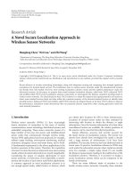
Fig. 6. Packet loss rate depends on the distance.
5.
Experiment and Results
To evaluate the performance of the system in
terms of the communication capability, we setup the
following scenario and measure the packet loss ratio.
Two monitoring nodes are deployed around the
gateway in urban environment in Hanoi. The distance
from a node to the gateway is varied from 500 m to
2000 m (illustrated in Fig. 5). The con guration
parameters of node are as follow: BW = 125KHz, SF
= 12, CR = 4/5, power = 14 dBm. The number of
messages transmitted per node is 500 messages, of
100 bytes. Figure 6 demonstrates the measurement
results of the test. The result shows that in the
communication at the distance less than 2 km is
reliable (the loss ratio is less than 4%).
6.
Conclusion
In this work, we design and implement the
monitoring system of radioactive sources using LoRa
communication technology. To solve the problem of
multiple access of nodes, we design and implement a
multiple access protocol based on Aloha scheme. As
a result, the system operates stable and the
communication is reliable when transmission range is
upto 2 km in urban environments. In subsequent
studies, the research team will develop advanced
functions based on AI and embedded the functions in
the LORA sensor nodes to form an intelligent
radiation sensor system.
[10]. U. Noreen, E. Ahcenebounceuruniv-brestfr, and L.
Clavier, A Study of LoRa Low Power and Wide Area
Network Technology.
[11]. de C. S. Jonathan, R. Joel, M. A. Antonio, and S. Peter,
LoRaWAN - A low power WAN protocol for Internet of
Things: A review and opportunities, 2017 2nd Int.
Multidiscip. Conf. Comput. Energy Sci., no. July, pp. 1–
6, 2017.
[12]. Semtech, SX1272/73 -860 MHz to 1020 MHz Low
Power Long Range Transceiver, no. Rev. 3.1, p. 129,
2017.
[13]. D. Bankov, E. Khorov, and A. Lyakhov, Mathematical
model of LoRaWAN channel access, 18th IEEE Int.
Symp. A World Wireless, Mob. Multimed. Networks,
WoWMoM 2017 - Conf., no. June, 2017.
Acknowledgments
This work is supported by the project T2018-PC-068
from Hanoi University of Science and Technology.
[14]. L. Casals, B. Mir, R. Vidal, and C. Gomez, Modeling the
Energy Performance of LoRaWAN, Sensors, vol. 17, no.
10, p. 2364, 2017.
References
[1].
[2].
INTERNATIONAL ATOMIC ENERGY AGENCY,
Control of Orphan Sources and Other Radioactive
Material in the Metal Recycling and Production
Industries, IAEA Saf. Stand. No. SSG-17, 2012.
[15]. G. Ferré, Collision and packet loss analysis in a
LoRaWAN network, 25th Eur. Signal Process. Conf.
EUSIPCO 2017, vol. 2017–Janua, pp. 2586–2590, 2017.
INTERNATIONAL ATOMIC ENERGY AGENCY,
Code of Conduct on the Safety and Security of
65