Optical simulation of planar CH3NH3PbI3 perovskite solar cells
Bạn đang xem bản rút gọn của tài liệu. Xem và tải ngay bản đầy đủ của tài liệu tại đây (920.89 KB, 9 trang )
VNU Journal of Science: Mathematics – Physics, Vol. 35, No. 3 (2019) 98-106
Original Article
Optical Simulation of Planar CH3NH3PbI3
Perovskite Solar Cells
Nguyen Duc Cuong1,*
Faculty of Engineering Physics and Nanotechnology, VNU University of Engineering and Technology,
144 Xuan Thuy, Cau Giay, Hanoi, Vietnam
Received 08 May 2019
Revised 24 May 2019; Accepted 30 May 2019
Abstract: In this work, optical simulation results of planar CH 3NH3PbI3 solar cells using a
MATLAB script developed by McGehee’s group (Stanford University) are presented. The device
structure is of FTO/HEL/AL/ETL/LiF/Al, where HEL is the hole-extraction layer, AL is the active
layer (CH3NH3PbI3), and EEL is the electron-extraction layer. In this MATLAB script, the transfer
matrix method was used, where transmission and reflection were calculated for each interface in
the stack as well as attenuation in each layer. The wavelength-dependent optical constants (n and
k) of each layer were measured by spectroscopic ellipsometry (SE). The exciton generation rates
within the active layer were calculated based on data of optical constants, as well as the thickness
of each layer. Considering the Internal Quantum Efficiency (IQE) equal to 100% at all
wavelengths, the predicted short-circuit currents (JSC) were also estimated. The obtained results
show a good agreement with the experimental values of JSC measured on real devices.
Keywords: planar solar cells, CH3NH3PbI3 perovskite, optical simulations, spectroscopic
ellipsometry.
1. Introduction
In recent years, perovskite solar cells have been attracting much attention due to their ease of
processing, low cost, and high Power Conversion Efficiency (PCE). The PCE of perovskite solar cells
based on the methylammonium lead iodide CH3NH3PbI3 (shortly as MAPbI3) has increased from 3.8%
in 2009 [1] to 19.2% in 2017 [2]. The PCE of multi-layer solar cells in general and planar perovskite
solar cells, in particular, is strongly varied depending not only on the optical and electrical properties
________
Corresponding author.
Email address:
https//doi.org/ 10.25073/2588-1124/vnumap.4349
98
N.D. Cuong / VNU Journal of Science: Mathematics – Physics, Vol. 35, No. 3 (2019) 98-106
99
of active layers as well as charge transport layers but also on the device structure, i.e. the thickness of
each layer. A high exciton generation rate, i.e. number of electron-hole pairs generated in a unit of
time and a unit of volume of the active layer is a crucial factor for a highly efficient solar cell.
Therefore, optical simulation steps help to find optimized structures for solar cells devices and to
reduce the cost of trial and error experiments.
In this paper, optical simulations using a MATLAB script developed by McGehee’s group
(Stanford University) [3], [4] were performed on planar multi-layer perovskite solar cells, utilizing
PEDOT:PSS (CLEVIOS P VP AI 4083) and Cu-doped NiOx (Cu:NiOx) as hole-extraction layers
(HEL), CH3NH3PbI3 (MAPbI3) as an active layer (AL) and PCBM as an electron-extraction layer
(EEL). In this MATLAB script, the transfer matrix method was used, where transmission and
reflection were calculated for each interface in the stack as well as attenuation in each layer, based on
optical constants of individual materials [5], [6]. The wavelength-dependent optical constants (n and k)
of each layer were measured by spectroscopic ellipsometry (SE) [7]. Briefly, by the SE, the change in
polarized light upon light reflection on a sample (or light transmission by a sample) was measured at
different wavelengths. Amplitude ratio and phase difference between p-and s-polarized light
waves were obtained directly from the measurement, and then optical constants (n and k) were found by
using an optical model relevant to the sample.
The exciton generation rates within layer j were calculated according to [5]:
G j x,
where Q j x,
4 c 0 n j k j
hc
Q j x,
(1)
E j x, is the time average of the energy dissipated per second in
2
2
layer j at position x at normal incidence, c is the speed of light, 0 is the permittivity of free space and
E j x, is internal optical electric field.
Considering the Internal Quantum Efficiency (IQE) equal to 100% at all wavelengths, the
predicted J SC also can be calculated according to:
J SC-predicted e GAL x, d dx
(2)
where GAL x, is the exciton generation rate within the active layer.
2. Experimental
The FTO-coated glass (7.33 Ω·sq–1) substrates were patterned by Zn powder and HCl acid (35%)
and cleaned by detergent and successive ultrasonic treatment in acetone, isopropanol before drying
under nitrogen flow. Right before deposition of hole-extraction layer (HEL), the FTO-coated glass
substrates were treated by UV-ozone for 30 min.
PEDOT:PSS (CLEVIOS P VP AI 4083) was filtered through a 0.45 μm PVDF filter before casting
on patterned FTO-coated glass substrates. Spin-coating at 3,000 rpm for 60 s and annealing at 150 °C
for 20 min in air produced a 40 nm thick PEDOT:PSS layer.
The Cu-doped NiOx HEL were deposited by spin-coating respective precursor on pre-cleaned FTO
substrates at 4,000 rpm for 30 s, followed by annealing at 550 °C for 30 min in air. The thickness of
Cu-doped NiOx measured by spectroscopic ellipsometry was 15.06±0.07 nm. Right before deposition
of active layers (ALs), the FTO/Cu:NiOx substrates were treated by UV-ozone for 10 min.
100
N.D. Cuong / VNU Journal of Science: Mathematics – Physics, Vol. 35, No. 3 (2019) 98-106
CH3NH3PbI3 (MAPbI3) layer was formed on FTO/HEL substrates by a single-step method with
non-solvent dripping [8]. PbI2 and MAI were dissolved in a mixture solvent of GBL and DMSO (7:3
v/v) at a concentration of 1.1 M under stirring at 60 °C for 12 h. The resulting solution was coated
onto the FTO/HEL substrates by a consecutive two-step spin-coating process at 1,000 and 5,000 rpm
for 10 and 20 s, respectively. During the second spin-coating step (at the eleventh second), the
substrate (3 cm × 3 cm) was treated with 0.6 ml of non-solvent (toluene, p-xylene or chlorobenzene)
drop-casting. Right after the spin-coating process, the films were transparent and colorless,
corresponding to the MAI-PbI2-DMSO intermediate phase. The substrate was then dried on a hot plate
at 100 °C for 10 min. All these steps were performed in a N2-filled glove box. The resulting films were
semi-transparent with dark-brown color, indicating the formation of the perovskite phase with good
crystalline quality.
A solution of Phenyl-C61-butyric acid methyl ester (PCBM) in chlorobenzene (20 mg/ml) was
spin-coated on the FTO/HEL/MAPbI3 substrate at 1000 rpm for 30 s, followed by annealing at 110 °C
for 10 min in a N2-filled glove box.
Finally, 0.5 nm of LiF and 120 nm of Al were subsequently deposited by thermal evaporation
under a 2.4×10⁻⁶ Torr vacuum on top of the devices to form the back contacts. A shadow mask was
used to define a 2×2 array of 0.4×0.6 cm2 rectangular contacts. The solar cells were then hermetically
encapsulated with glass cover using an ultraviolet-curable epoxy sealant (XNR5570-A1 NAGASE
ChemTex), with an ultraviolet exposure of 2 min.
Absorbance spectra were taken by a Jasco V670 UV-Vis-NIR spectrophotometer equipped with an
integrating sphere.
Thin films for SE measurements were prepared on Si/SiO2 substrates following the same recipes
mentioned above. SE spectra were measured by a V-VASE Ellipsometer (J. A. Woollam) and
analyzed by CompleteEASE Software (version 5.01, J. A. Woollam) [9].
Side-view Scanning Electron Microscopy (SEM) image was taken from a Hitachi ultrahighresolution/SEM S-4800 scanning electron microscope.
3. Results and discussion
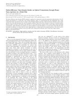
Figure 1 shows the wavelength-dependent spectra of the two ellipsometry parameters ( , ) and
respective optical constants ( n, k ) of a MAPbI3 thin film formed on Si/SiO2 substrate. Here the fitting
procedure according to the Cauchy optical model yielded not only optical constants ( n, k ), but also the
thickness of 178.656±0.199 nm of the MAPbI3 thin film with a mean-squared error (MSE) of 4.881. A
closer look at the extinction coefficient ( k ) spectrum revealed that the onset is observed at around 760
nm, while a shoulder and a peak are observed at 480 nm and 360 nm, respectively [10], [11]. Those
positions are totally consistent with the absorbance spectrum (dashed line) measured by a UV-VisNIR spectrometer. In addition, those positions are in good agreement with the previous report of Even
et al., who pointed out that the broad light-harvesting abilities of the inorganic-organic family of
perovskites CH3NH3PbI3 are a direct consequence of their multi-bandgap and multi-valley nature [12].
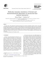
Optical constants of other materials were obtained in a similar manner. Figure 2 shows optical
constants of FTO, PEDOT:PSS (CLEVIOS P VP AI 4083), Cu:NiOx, MAPbI3, and PCBM. The
absorption coefficient ( ) of MAPbI3 estimated as 98522 cm–1 at 550 nm, according to the following
relation:
4 k
(3)
N.D. Cuong / VNU Journal of Science: Mathematics – Physics, Vol. 35, No. 3 (2019) 98-106
101
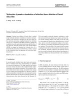
Tauc plot (i.e. h vs. h ) for direct bandgap materials shown in Figure 3 reveals that the
optical band gap of MAPbI3 is 1.609 eV, that is slightly larger than the value obtained by theoretical
calculations [13] but smaller than the value obtained by PL measurements [10], [11].
2
Figure 1. Wave-length dependent spectra of ( , ) and respective optical constants ( n, k ) obtained from a
MAPbI3 thin film formed on a Si/SiO2 substrate. Absorbance spectrum (dashed line) measured by a UV-Vis-NIR
spectrometer is also shown for comparison.
Figure 2. Wavelength-dependent optical constants ( n, k ) of FTO, PEDOT:PSS (CLEVIOS P VP AI 4083),
Cu:NiOx, MAPbI3, and PCBM.
102
N.D. Cuong / VNU Journal of Science: Mathematics – Physics, Vol. 35, No. 3 (2019) 98-106
Figure 3. Tauc plot of MAPbI3. Absorption coefficient ( ) were estimated by 4 k and extinction
coefficient k was obtained from spectroscopic ellipsometry measurements (See Figure 1).
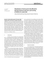
Figure 4. Side-view SEM image of FTO/Cu:NiOx/MAPbI3/PCBM stacked layers. Thicknesses of FTO
(including Cu:NiOx), MAPbI3 and PCBM layers are 698, 212 and 49.6 nm, respectively. Cu:NiOx layer
(thickness of ~15 nm measured by SE) is too thin to be distinguished between FTO and MAPbI 3 layers.
Optical constants data of each material were then put into an Excel file, which serves as input data
for the MATLAB script [3]. In addition, the names of materials which build the structure of the cell
and their corresponding thickness (in nm) were also given in the script. According to the side-view
SEM image (Figure 4), the thickness of each layer of the device can be exactly determined. The
thickness of PEDOT:PSS of 40 nm were determined by an α-step instrument. Simulations were
N.D. Cuong / VNU Journal of Science: Mathematics – Physics, Vol. 35, No. 3 (2019) 98-106
103
performed with wavelength ranging from 300 to 1000 nm and the output data of the calculation
includes internal optical electric field, exciton generation rate within the active layer, and predicted
short-circuit current J SC . With minor justification, the device structure of FTO(580
nm)/HEL/MAPbI3(210 nm)/PCBM(50 nm)/LiF(0.5 nm)/Al(120 nm) were used as a standard. The
position-dependent exciton generation rate within the MAPbI3 active layer at various wavelengths
GAL x, for two solar cells using PEDOT:PSS(40 nm) and Cu:NiOx(15 nm) HELs are shown in
Figure 5. In both cases, the maxima of GAL x, occur at the HEL/AL interface and wavelength of
450 nm, with the values of 6.046×10¹⁹ s–1·cm–1·nm–1 and 6.147×10¹⁹ s–1·cm–1·nm–1 for PEDOT:PSSbased and Cu:NiOx-based devices, respectively. Figure 6 shows the position-dependent exciton
generation rate (obtained by integration by wavelengths varying from 300 nm to 1000 nm) within the
MAPbI3 active layer. Due to the lower absorption coefficient of Cu:NiOx as compared to that of
PEDOT:PSS (Figure 2), the exciton generation rate of Cu:NiOx-based device is higher than that of
PEDOT:PSS-based device over the whole active layer. Such distribution of generation rate requires
long diffusion length of electron in MAPbI3 material and good electron conductivity of EEL material
to facilitate electron extraction at the cathode, and hence yield high J SC . Fortunately, Xing et al.
(2013) have discovered balanced long-range electron-hole diffusion lengths of at least 100 nanometers
in solution-processed MAPbI3 [11], which merely satisfies that requirement.
Based on the aforementioned standard device structure, the thickness of each layer was
systematically varied. The dependence of predicted J SC on the thickness of each layer is presented in
Figure 7. Due to the same reason mentioned above, the reduction of J SC-predicted with the thickness of
PEDOT is much faster than with thickness of Cu:NiOx. As a result, J SC-predicted of PEDOT-based device
is smaller than Cu:NiOx-based device for most values of MAPbI3 thickness (Figure 7(c)). Finally,
although the PCBM layer is close to the back contact, it also has a noticeable impact on the J SC-predicted
and causes J SC-predicted to reduce as dPCBM 10 nm (Figure 7(d)).
Figure 5. Position-dependent exciton generation rate at various wavelengths GAL x, (see Equation 1) within
the MAPbI3 active layer for planar solar cells with (a) PEDOT:PSS(40 nm) and (b) Cu:NiO x(15 nm) HEL.
104
N.D. Cuong / VNU Journal of Science: Mathematics – Physics, Vol. 35, No. 3 (2019) 98-106
Figure 6. The variation of exciton generation rates within the MAPbI 3 AL with distance from HEL/AL interface
for devices with PEDOT:PSS(40 nm) and Cu:NiOx(15 nm) HELs.
Figure 7. Dependence of predicted (maximum) J SC-predicted on the thickness of PEDOT:PSS, (b) Cu:NiOx, (c)
MAPbI3 and (d) PCBM considering the Internal Quantum Efficiency (IQE) equal to 100% at all wavelengths.
N.D. Cuong / VNU Journal of Science: Mathematics – Physics, Vol. 35, No. 3 (2019) 98-106
105
Stacked device FTO(580 nm)/HEL/MAPbI3(210 nm)/PCBM(50 nm)/LiF(0.5 nm)/Al(120 nm)
with PEDOT:PSS(40 nm) and Cu:NiOx(15 nm) HELs has predicted J SC of 16.59 mA/cm2 and 17.97
mA/cm2, respectively. Interestingly, those values are in good agreement with the experimental data of
J SC ( J SC-experimental ), which has been reported in [14]. The ratio between predicted and experimental
J SC is defined as:
J SC-experimental
J SC-predicted
(4)
The value of estimated for PEDOT:PSS- and Cu:NiOx-based devices are 95.24% and 100.78%,
respectively. Considering the electron-extraction efficiencies at the PCBM side are identical for both
devices, those values of indicate that the hole-extraction efficiency Cu:NiOx is better than
PEDOT:PSS, that is crucial for the balance between electron and hole currents and hence high
photocurrent.
4. Conclusions
In this work, optical simulations on planar CH3NH3PbI3 perovskite solar cells using transfer matrix
method were performed. The evaluated short-circuit currents showed a good agreement with the
experimental data measured on real devices. As a result of those simulations, position-dependent
exciton generation rates have been exactly determined and can serve as input data for the electrical
simulation tools such as SCAPS [15]. It is worth to note that this method can be applied to all planar
solar cells including organic solar cells, Si-based solar cells, and multi-junction solar cells.
Acknowledgements
This work has been supported by VNU University of Engineering and Technology under project
number CN18.05. The author greatly appreciates Prof. Soonil Lee (Ajou University, Republic of
Korea) for valuable comments and Dr. Sung-yoon Jo (KIST, Republic of Korea) for technical
assistance in spectroscopic ellipsometry analyses.
References
[1] A. Kojima, K. Teshima, Y. Shirai, T. Miyasaka, Organometal halide perovskites as visible-light sensitizers for
photovoltaic cells, J. Am. Chem. Soc. 131 (2009) 6050–6051. />[2] Y. Wu, F. Xie, H. Chen, X. Yang, H. Su, M. Cai, Z. Zhou, T. Noda, L. Han, Thermally stable MAPbI3 perovskite
solar cells with efficiency of 19.19% and area over 1 cm2 achieved by additive engineering, Adv. Mater. 29
(2017) 1701073(1–8). />[3] G.F. Burkhard, E.T. Hoke, Transfer matrix optical modeling, McGehee Group (Stanford Univ). 2011. Available
online: (accessed 10 October 2018).
[4] G.F. Burkhard, E.T. Hoke, M.D. McGehee, Accounting for interference, scattering, and electrode absorption to
make accurate internal quantum efficiency measurements in organic and other thin solar cells. Adv. Mater., 22
(2010) 3293–3297. />[5] L.A.A. Pettersson, L.S. Roman, O. Inganäs, Modeling photocurrent action spectra of photovoltaic devices based
on organic thin films, J. Appl. Phys. 86 (1999) 487–496. />
106
N.D. Cuong / VNU Journal of Science: Mathematics – Physics, Vol. 35, No. 3 (2019) 98-106
[6] P. Peumans, A. Yakimov, S. Forrest, Small molecular weight organic thin-film photodetectors and solar cells, J.
Appl. Phys. 93 (2003) 3693–3723. />[7] H. Fujiwara, Spectroscopic Ellipsometry : Principles and Applications, John Wiley & Sons, 2007.
[8] N.J. Jeon, J.H. Noh, Y.C. Kim, W.S. Yang, S.C. Ryu, S.I. Seok, Solvent engineering for high-performance
inorganic–organic hybrid perovskite solar cells, Nat. Mater. 13 (2014) 897–903.
/>[9] CompleteEASE - J.A. Woollam. (accessed 15
September 2018).
[10] S.D. Stranks, G.E. Eperon, G. Grancini, C. Menelaou, M.J.P. Alcocer, T. Leijtens, L.M. Herz, A. Petrozza, H.J.
Snaith, Electron-hole diffusion lengths exceeding 1 micrometer in an organometal trihalide perovskite absorber.
Science 342, 2013, 341–344. />[11] G. Xing, N. Mathews, S. Sun, S.S. Lim, Y.M. Lam, M. Grätzel, S. Mhaisalkar, T.C. Sum, Long-range balanced
electron- and hole-transport lengths in organic-inorganic CH3NH3PbI3, Science 342 (2013) 344–347.
/>[12] J. Even, L. Pedesseau, C. Katan, Analysis of multi-valley and multi-bandgap absorption and enhancement of free
carriers related to exciton screening in hybrid perovskites, J. Phys. Chem. C 118 (2014), 11566–11572.
/>[13] P. Umari, E. Mosconi, F. De Angelis, Relativistic GW calculations on CH 3NH3PbI3 and CH3NH3SnI3 perovskites
for solar cell applications, Sci. Rep. 4 (2014), 1–7. />[14] D.C. Nguyen, S. Joe, N.Y. Ha, H.J. Park, J. Park, Y.H. Ahn, S. Lee, Hole‐extraction layer dependence of defect
formation and operation of planar CH3NH3PbI3 perovskite solar cells, Phys. status solidi - Rapid Res. Lett. 11
(2016) 1600395(1–5). />[15] A. Niemegeers, M. Burgelman, K. Decock, S. Degrave, V. Johan, SCAPS (a Solar Cell Capacitance Simulator).
Available online: (accessed 25 February 2019).