Growth mechanisms of single wall carbon nanotubes in a chemical vapor deposition (CVD) process on Fe/Mo-Al catalyst
Bạn đang xem bản rút gọn của tài liệu. Xem và tải ngay bản đầy đủ của tài liệu tại đây (3.62 MB, 9 trang )
Science & Technology Development, Vol 16, No.K1- 2013
GROWTH MECHANISMS OF SINGLE-WALL CARBON NANOTUBES IN A
CHEMICAL VAPOR DEPOSITION (CVD) PROCESS ON Fe/Mo-Al CATALYST
Le Van Thang
University of Technology, VNUHCM
(Manuscript Received on April 5th, 2012, Manuscript Revised May 15th, 2013)
ABSTRACT: The formation mechanisms involved in the growth of single-walled carbon
nanotubes (SWNTs) by chemical vapor deposition (CVD) was studied. Transmission electron
microscopy (TEM) was used to analyze the encapsulated metal catalyst particles found within the tubes,
and the dimensions and location of these particles was determined. SWNTs were found to have
encapsulated particles in the end of tubes, with large length to diameter ratios. As a result of these
observations, we concluded that SWNTs are formed via an open-ended, base-growth mechanism (VLS
mechanism). Additionally, we have demonstrated the formation of two kinds of bundles of SWNTs
(Parallel bundles and as-rope bundles). SWNTs grown with thermal CVD on Fe/Mo-Al catalyst did not
contain similar elongated particles or particles along the middle of the tubes, indicating that these new
growth mechanisms are only applicable in the case of tubes grown via vapor phase CVD growth
methods.
Keywords: Carbon nanotubes, base-growth mechanism, Transmission electron microscopy
understood. It may be different depending on
1. INTRODUCTION
which method is used.
Since their discovery nearly twenty years
ago, single wall carbon nanotubes (SWNT)
have been the focus of numerous investigations
because of their unique and superior electronic,
chemical, physical and mechanical properties,
representing the ultimate carbon fiber [1-8].
But one major challenge is to control the
growth of SWNTs, in particular concerning
their diameter and helicity. To achieve a
controllable growth of the CNTs with high
quality,
understanding
of
their
growth
mechanism is of importance, which still
remains an open question [1]. Naturally, the
growth mechanism of nanotubes is not well
Trang 72
It is known that the arc-discharge and
laser-ablation method lead to growth of
MWNT without using metal catalyst whereas
for carbon nanotubes to be synthesized with the
CVD method, the catalyst particles are
necessary. In contrast, for the growth of
SWNTs, catalysts play an important role for all
three methods mentioned above [1, 6-8].
Carbon nanotubes produced using the CVD
method exhibit high purity, high yield, and
perfect orientation. According to the different
growth modes of CNTs by CVD, scientists
have
proposed several kinds
of growth
TAẽP CH PHAT TRIEN KH&CN, TAP 16, SO K1- 2013
mechanisms: base growth mechanism, tips
substrate. All materials used in experiments are
growth mechanism [2, 3], Yarmulke growth
research grade materials purchased from
mechanism [9] etc. Dai et al. and Kukovitsky et
different
al. [10] have put forward vaporliquidsolid
MoO2(acetyl acetone)2 were purchased from
(VLS) mechanism. In this mechanism, liquid
Sigma Aldrich chemicals. Oxide C alumina
catalytic particles at high temperature accepted
obtained from Degussa Inc. Air product
carbon atoms from the vapor, causing the
provided high-purity methane and hydrogen.
liquid
to
become
supersaturated,
the
supersaturated carbon atoms then deposited to
form CNTs. The liquid catalytic particles acted
as the medium for transport from the vapor to
the crystal and the CNTs grew by the
deposition of supersaturated carbon atoms. In
VLS model, molecular decomposition and
carbon solution are deposited at one side of the
catalytic particle. Carbon diffuses from the side
where it has been decomposed to another side
where it is precipitated from solution. The
metalsupport interactions are found to play a
determinant role for the growth mechanism.
In the present work SWNTs have been
synthesized by the catalytic decomposition of
suppliers.
Fe(NO3)3.9H2O,
and
2.2 Catalyst preparation
In the initial methane CVD method, we
used
an
Fe(NO3)3.9H2O,
MoO2(acetylacetone)2, and 30 mg of alumina
nanoparticles
impregnation
catalyst
in
Fe(NO3)3.9H2O,
prepared
by
40
of
methanol.
3
mg
mg
of
MoO2(acetylacetone)2, and 30 mg of Alumina
nanoparticles are mixed in 30 ml of methanol
and sonicated for 1/2 hr. Then, the liquid
catalyst is deposited onto the substrate by
micropipette.
2.3 Carbon nanotubes growth
Catalyst materials were deposited onto the
methane, over FeMoAl catalyst in a tube
Si/SiO2
substrate
were
calcined
in
Ar
furnace, which allows continuous control of the
environment at 400C for 15 minutes, cooled to
CNT synthesis in real time. The properties of
room temperature, and put it inside a 3 inches
CNTs have been studied using SEM, RAMAN
diameters quartz tube mounted in an electric
and TEM. Based on our TEM results, a growth
tube furnace. The quartz was heated from room
mechanism is described.
temperature to 900C under Ar flow at a flow
rate of 1000 sccm. The reaction began when
2. EXPERIMENTAL
The nanotubes were grown by a thermal
CVD of methane at atmospheric pressure.
2.1. Materials
adding H2:CH4(250:1000sccm)for the desired
reaction time (14 mins). The flow was then
switched to Ar and the furnace was cooled to
room temperature.
Silicon (100) wafer with surface oxide
layer of thickness 1 m was used as the
Trang 73
Science & Technology Development, Vol 16, No.K1- 2013
2.4. Characterizations
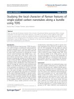
3.2. Carbon nanotube characterization
SWNT samples were fully characterized
using SEM, TEM and Raman spectroscopy.
Figure 2 is micrograph of the nanotubes
growth sample prepared in our process.
The growth mechanism of SWNTs in the
However, those nanotubes are multi-walled or
determined
single-walled tubes were firstly verified Raman
systematic by TEM imaging of nanotube ends.
spectroscopy. This technique is useful in
Using TEM grids as substrates for the growth
distinguishing between the MWNTs and
of carbon nanotubes is a very simple approach.
SWNTs because the spectra of them contain
The TEM grids are thin metal foils with
special vibration modes.
methane
CVD
process
was
punched holes. The grids have a diameter of
3.05 mm and a thickness of 12 to 15 m. The
melting point of the grids’ metals is higher than
1000°C which means that the grids should
withstand the growth process.
3. RESULTS AND DISCUSSION
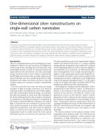
3.1. Catalyst on the copper grid
The suspension catalyst was covered on
thecopper grid by the
micropipette and
a
b
Figure 2. SEM image of CNTs production
characterized with TEM.
3000
b
2500
500
400
1
6
G
300
2000
1
4
200
2
0
1
8
100
1500
0
150
200
2 2
26 6
5
2
7
250
300
1000
Mode TM
RBM
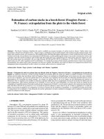
Figure 1. TEM images of catalyst on the copper grid
500
TEM images shown catalyst particles with
0
D
different sizes. Diameter of catalytic grains in
fig. 1a was smaller than that of alumina
particles (13nm). So, these particles are the
grains of active catalyst.
20
30
130
140
160
Figure 3. Raman spectroscopy of CNTs products
We were characterized SWNTs properties
by a Raman microscope system (YVON) at an
excitation wavelength of 514.5 nm.
Trang 74
150
Frequency (cm-
TAẽP CH PHAT TRIEN KH&CN, TAP 16, SO K1- 2013
The diameter
(d) is determined
by
measuring the RBM frequency and applying
the formula:
RBM = 224/d (nm)
Raman spectra show several RBM signals,
suggesting that the grown SWNTs are bundles
or individuals nanotubes. The frequency range
for the observed RBM signals (120300 cm-1)
corresponds to tube diameters from 0.8 to 2
nm.
In the high-frequency range of the Raman
spectra, we observe a prominent G-band (
1590 cm-1) and the weak D-band (~1350 cm-1).
As it is well known, the G-band intensity is
Figure 4. TEM images of as-grown CNTs on
approximately proportional to density of
Molybdenum grid
SWNTs. The D-band is related to the structural
disorder of sp2 bonded nanocrystalline and/or
amorphous carbon species. Its low intensity is
indicating that very few defects are presents in
these SWNTs. The quality of the tubes can be
also identified using the very low ratio between
the D-band and G-band (0.1 -0.05).
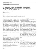
3.3. TEM images of carbon nanotube on the
molybdenum grid
The results of the experiments with TEM
Figure 5. TEM images of Bundle SWNTs
grid can be summarized as follow:
The TEM pictures are taken at the Center
for
Nanoscale
characterization,
MINATEC/LETI. Long CNTs can be seen in
the figure 4 that were produced by CVD
process at 900C. The length of this particular
CNT is about few ten of micrometers.
Figure 6. TEM images of individual SWNTs
Trang 75
Science & Technology Development, Vol 16, No.K1- 2013
Amorphous carbon structures are also
observed together with the CNTs (inset in fig
5)
TEM pictures show the bundles (fig. 5) and
individual
(fig.
6)
single-walled
carbon
nanotubes. These nanotubes have diameter of
around 1.4 nm. The observed bundle SWNT
includes some parallel tubes with diameter in
the range of 1.3-1.6 nm.
5nm
Graphene layers covering the catalyst
nanoparticles are seen together with catalyst
particles in fig 6.
5nm
In summary, TEM studies of carbon
nanotubes demonstrated different single walled
carbon nanotubes (the individual and bundles
of SWNTs). In some of images, catalyst
particles, on which the carbon nanotubes were
grown, were also observed. In our case, most of
the individual SWNTs have diameter smaller
than 2 nm. However, there are also some other
nano-objects produced in the system such as
amorphous carbon or graphene layers. The
5nm
TEM results also confirmed that the MWNT
and DWNT didn’t grow on our process.
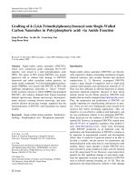
3.4. The growth mechanism of CNT
With TEM images, we found that the
Figure 7. A typical HRTEM images of the tips of
bottoms of nanotubes are attached by small
individual SWNTs synthesized on Fe2O3-MoO3/
catalyst particles. In all cases, it is found that
Al2O 3 catalyst
the bottoms with catalyst nanoparticles are
always anchored on the alumina support (red
arrows in fig 7).
Trang 76
TAẽP CH PHAT TRIEN KH&CN, TAP 16, SO K1- 2013
which was introduced to explain the growth of
carbon nanotubes.
In our base-growth model, at the early
stage of the CVD reaction, carbon atoms
catalytically decomposed from the methane are
absorbed
onto the
nanoparticles
surface,
forming carbon-active catalyst liquid-state. As
discussed above, this liquid-state is reached
because of the active catalyst particles have
nanometre sizes: leading to reduced melting
Figure 8. TEM images of SWNTs without catalytic
points. If the methane supply to the process
particles at the top
continues, a super saturation point of carbon in
liquid state is reached, carbon precipitates out
from the nanoparticles surface. This leads to
the growth of single-walled carbon nanotubes.
The growth stops when the methane becomes
insufficient or the active catalyst particle is
poisoned by reaction (fig. 10).
Active catalyst
methane
Al2 O3 support
Figure 9. TEM images of the top of SWNTs
Figure 8 and 9 show that the top of the
tubes can extend out of the grid. Importantly,
SiO2/Si
Figure 10. A schematic growth mechanism of
individual SWNTs from catalyst nanoparticles
we have not seen a SWNT extending out of
grid with the catalyst nanoparticles on the top
(bright green arrows in figure 8 and 9).
For
bundles
of single-walled carbon
nanotubes, the growth mechanism is the same
as with individual SWNTs.
Based on the states of the nanotubes ends
and the TEM results, we propose that SWNTs
grow via the base-growth model. And to
explain the growth mechanism of carbon
nanotubes in methane CVD process, we
propose the vapor-liquid-solid (VLS) model
Trang 77
Science & Technology Development, Vol 16, No.K1- 2013
Figure 11. Some parallel SWNTs in bundles
In our SWNTs products, we obtain two
kinds of bundle:
- Parallel SWNTs in bundles (fig 11)
- As-rope SWNTs in bundles (fig 12):
some individual nanotubes are twisted into a
rope
These bundles of SWNTs products can
explain by the important role of the fume and
porous alumina support. As already stated, the
fume
alumina
material
(-Al2O3)
are
anisotropic since they contain crystal edges,
corners, and hydroxyl groups (-OH).
Figure 12. TEM images of as-rope SWNTs
As-rope SWNTs in bundles
So, the active catalyst particles form the
strongly interaction with the support’s surface.
Parallel SWNTs in bundles
methane
methane
Al2O3 support
This phenomenon allows to the formation of
numerous of active centers on the support’s
SiO2/Si
SiO2/Si
surface. These active centers are very close
together. This leads to growth of the bundles of
Figure 13. Growth mechanism of bundles SWNTs
nanotubes. The kinds of bundles of SWNT
during CVD process
depend on the position of active catalyst and
4. CONCLUSION
the growth direction (fig. 13)
The production of high-quality of singlewalled carbon nanotubes by catalyst CVD
method has been achieved. The producedSWNTs are a mixture of the semiconducting
and metallic SWNTs with the diameters in the
range of 0.8-1.8 nm. However, the experiment
results also confirmed that our products
Trang 78
TẠP CHÍ PHÁT TRIỂN KH&CN, TẬP 16, SỐ K1- 2013
contained
impurities
(amorphous
carbon,
nanotubes in methane CVD process. Besides,
graphite layer)
we have demonstrated the formation of two
kinds of bundles of SWNTs (Parallel bundles
We have suggested the ‘base-growth”
and as-rope bundles).
mechanism of individual single-walled carbon
NGHIÊN CỨU CƠ CHẾ PHÁT TRIỂN CỦAỐNG NANO CARBON ĐƠN THÀNH
TỔNG HỢP TRÊN XÚC TÁC Fe/Mo-Al BẰNG THIẾT BỊ NGƯNG TỤ HƠI HỐ
HỌC
Lê Văn Thăng
Trường Đại học Bách Khoa, ĐHQG-HCM
TĨM TẮT: Cơ chế phát triển ống nano carbon đơn thành được tổng hợp bằng thiết bị ngưng tụ
hơi hố học đã được xác định. Phương pháp phân tích bằng kính hiển vi điện tử truyền qua (TEM) đạ
được sử dụng để quan sát vị trí, hình thái của các hạt xúc tác. Nghiên cứu đã xúc định được các hạt xúc
tác đều được cố định ở chân của các ống nano carbon đơn thành. Đây chính là kết quả quan trọng nhất
cho thấy cơ chế phát triển ống nano carbon đơn thành trong nghiên cứu này là cơ chế “phát triển từ
chân”. Bên cạnh đó, từ kết quả TEM, hai cơ chế phát triển mới của ống nano carbon dạng bó cũng
được xác định: cơ chế phát triển “ bó song song” và cơ chế phát triển “bó xoắn”. Nghiên cứu cũng
đồng thời khẳng định các hạt xúc tác khơng hề tồn tại ở trong và trên đỉnh của ống nano carbon, điều
này cho thấy đây là một cơ chế đặc trưng cho trường hợp tổng hợp ống nano carbon bằng thiết bị
ngưng tụ hơi hố học từ pha hơi.
Từ khóa: Ống nano carbon đơn thành, cơ chế phát triển từ gốc, kính hiển vi điện tử truyền qua.
walled carbon nanotubes, J Phys Chem B,
REFERENCES
[1].
Science, 50, 929–961 (2005).
[2].
[3].
103:6484–92 (1999).
A.-C. Dupuis, Progress in Materials
[4].
Dresselhaus MS, Dresselhaus G, Eklund P
Baker RTK, Catalytic growth of carbon
C, Science of Fullerenes and Carbon
filaments. Carbon, 27: 315–23 (1989).
Nanotubes (San Diego, CA: Academic),
Cassel AM, Raymakers A, Kong J, Dai
965 (1996).
H.,Large scale CVD synthesis of single-
[5].
Justin Tan Wee Khiang, Electrochemical
Storage
of
Hydrogen
Using Carbon
Trang 79
Science & Technology Development, Vol 16, No.K1- 2013
Nanotubes,
[6].
[7].
Faculty
of
Engineering,
Dai H, Rinzler A G, Nikolaev P, Thess A,
Physical Sciences and Architecture.
Colbert D T and Smalley R E,Single-wall
Pulickel M. Ajayan and Otto Z. Zhou.
nanotubes produced by metal-catalyzed
Applications of Carbon Nanotubes, Appl.
disproportionation
Phys, 80, 391–425 (2001).
monoxide,Chem. Phys. Lett., 260, 471–5
M. Meyyappan,Carbon nanotubes science
(1996).
and applications, CRC PRESS(2005).
[8].
[9].
of
carbon
[10]. E.F. Kukovitsky, S.G. L’vov, N.A. Sainov,
A. Loiseau P. Launois P. Petit, S. Roche
VLS-growth of carbon nanotubes from the
J.-P.
vapor,
Salvetat,
Understanding
Nanotubes, Springer (2006).
Trang 80
Carbon
Chemical
317_2000, 65–70.
Physics
Letters,