A simple analytical method to estimate all exit parameters of a cross-flow air dehumidifier using liquid desiccant
Bạn đang xem bản rút gọn của tài liệu. Xem và tải ngay bản đầy đủ của tài liệu tại đây (668.05 KB, 8 trang )
Journal of Advanced Research (2014) 5, 175–182
Cairo University
Journal of Advanced Research
ORIGINAL ARTICLE
A simple analytical method to estimate all exit
parameters of a cross-flow air dehumidifier using
liquid desiccant
M.M. Bassuoni
*
Mechanical Power Engineering Department, Faculty of Engineering, Tanta University, Egypt
A R T I C L E
I N F O
Article history:
Received 16 December 2012
Received in revised form 5 February 2013
Accepted 23 February 2013
Available online 30 March 2013
Keywords:
Dehumidifier
Regenerator
Liquid desiccant
Analytical solution
Structured packing bed
Desiccant cooling
A B S T R A C T
The dehumidifier is a key component in liquid desiccant air-conditioning systems. Analytical
solutions have more advantages than numerical solutions in studying the dehumidifier performance parameters. This paper presents the performance results of exit parameters from an analytical model of an adiabatic cross-flow liquid desiccant air dehumidifier. Calcium chloride is
used as desiccant material in this investigation. A program performing the analytical solution
is developed using the engineering equation solver software. Good accuracy has been found
between analytical solution and reliable experimental results with a maximum deviation of
+6.63% and À5.65% in the moisture removal rate. The method developed here can be used
in the quick prediction of the dehumidifier performance. The exit parameters from the dehumidifier are evaluated under the effects of variables such as air temperature and humidity, desiccant
temperature and concentration, and air to desiccant flow rates. The results show that hot humid
air and desiccant concentration have the greatest impact on the performance of the dehumidifier. The moisture removal rate is decreased with increasing both air inlet temperature and desiccant temperature while increases with increasing air to solution mass ratio, inlet desiccant
concentration, and inlet air humidity ratio.
ª 2013 Cairo University. Production and hosting by Elsevier B.V. All rights reserved.
Introduction
Ongoing increase in the air-conditioning load which is the sum
of the sensible and latent load represents 20–40% of the overall
energy consumption in a building [1]. Dehumidification
* Tel.: +20 1005852335.
E-mail address:
Peer review under responsibility of Cairo University.
Production and hosting by Elsevier
handles the latent load, while sensible cooling handles other
load portion. Traditional vapor compression equipment
overcools air-stream to provide cooling and dehumidification.
Air-conditioning operates at a temperature colder than the
supply air dew-point temperature, so the supply air needs
reheating before entering the space to ensure indoor air
quality. Liquid desiccant dehumidifier is used as an alternative
to the conventional air dehumidification systems. An energy
savings, relative to conventional vapor compression systems,
of up to 40% can be achieved by using a desiccant assisted
air-conditioning system [2]. One-dimensional differential heat
and mass transfer models are well established and were
frequently used to study the performances of packed bed
dehumidifiers and regenerators. A theoretical model for a test
2090-1232 ª 2013 Cairo University. Production and hosting by Elsevier B.V. All rights reserved.
/>
176
M.M. Bassuoni
Nomenclature
Cp
h
m_
P
T
X
y
specific heat at constant pressure, kJ/kg K
enthalpy, kJ/kg
mass flow rate, kg/s
pressure, Pa
temperature, °C
desiccant solution concentration, kgd/kgs
air humidity ratio, kgv/kgda
Subscripts
da
dry air
a
air
column with LiBr solutions was developed by Factor and
Grossman [3]. The interface temperature and concentration
were assumed to be the bulk liquid temperature and concentration. Overall, heat and mass transfer coefficients were utilized.
The model was validated with the experimental results. For
CaCl2, LiCl and cost effective liquid desiccant solutions
(CELD), the individual phase heat and mass transfer coefficients were calculated and correlated for various packing materials [4,5]. Analytical expressions of the air and desiccant
parameters in the counter flow dehumidifier are provided by
Stevens et al. [6]. Within the model, the analytical solution of
the air enthalpy and liquid desiccant equivalent enthalpy,
which expressed the capability of the combined heat and mass
transfer process, is first calculated. Then, the solutions of the
air humidity ratio and desiccant equivalent humidity ratio,
which expresses the capability of moisture transfer, are given.
Finally, the air and liquid desiccant temperature can be calculated according to the above enthalpy and humidity ratio calculated result. A method for finding the analytical solution of
the coupled heat and mass transfer performance for the dehumidifier and regenerator was reported before [7,8]. Analytical
solutions of the air enthalpy and desiccant equivalent enthalpy
field within the cross-flow dehumidifier/regenerator were given
[9,10], where the air and desiccant are not mixed breadthwise
(which means the transfer processes of the air and desiccant
are both two dimensional). The enthalpy field gained from
the analytical solutions compares well with numerical solutions, and the analytical enthalpy efficiency compares well with
experimental results of the cross-flow dehumidifier.
Researchers [11–13] have developed mathematical models
of the coupled heat and mass transfer processes in the dehumidifier or regenerator, and most of the models were solved
numerically. In Liu et al. [14], an experimental study of the
performance of the cross-flow dehumidifier was done, which
has been less studied than the counter flow dehumidifier,
although it is more applicable in practice. The moisture removal rate and dehumidifier effectiveness were adopted as
the dehumidifier performance indices. The effects of the dehumidifier inlet parameters on the two indices were investigated.
Correlations have been proposed to predict the cross-flow
dehumidifier performance, which give results in good agreement with the present experimental findings. The results from
studying the performance of a counter flow liquid desiccant
dehumidifier were presented by Koronaki et al. [15]. A heat
and mass transfer theoretical model of an adiabatic packed
cond
d
eq
s
v
1
2
condensed
desiccant
equilibrium
desiccant solution
vapor
inlet
exit
Greek symbols
e
effectiveness
column has been developed, based on the Runge–Kutta fixed
step method, to predict the performance of the device under
various operating conditions. Good agreement was found between experimental tests and the theoretical model. Davoud
and Meysam [16] presented a new analytical solution of heat
and mass transfer processes in a packed bed liquid desiccant
dehumidifier. They results revealed that design variables such
as desiccant concentration, desiccant temperature, air flow
rate, and air humidity ratio have the greatest impact on the
performance of the dehumidifier. The liquid flow rate and
the air temperature have not a significant effect. Furthermore,
the effects of air and liquid desiccant flow rate have been reported on the humidity effectiveness of the column.
Heat and mass transfer coefficients were used to numerically solve most models in the literature. This paper proposed
a simple analytical model of the bulk heat and mass transfer
processes in a cross-flow liquid desiccant air dehumidifier.
An empirical correlation for calculating the dehumidifier effectiveness introduced by Moon et al. [17] is used to perform the
analytical solution of the presented model with acceptable
accuracy. Comprehensively, this model is used for studying
the effect of operating parameters on the whole dehumidifier
performance. The analytical solution shows good accuracy
when compared with reliable experimental data available in
the literature.
System description
Based on energy and mass laws of conservations, the proposed
analytical model has been developed as a tool for evaluating
the performance of a cross-flow liquid desiccant air dehumidifier. This model describes rationally the bulk coupled heat and
mass transfer processes taking place inside the dehumidifier.
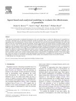
From Fig. 1, the strong desiccant solution is supplied to the
dehumidifier at suitable concentration and temperature. At
the same time, process air flows continuously across the dehumidifier. Due to the vapor pressure difference between air and
desiccant solution, the process air is dehumidified. The dryer
the exit air is, the higher the rate of water vapor absorbed by
the strong desiccant solution which leads to weak desiccant
solution at the dehumidifier exit. The following initial parameters should be assumed during calculation procedure: concentration and temperature of desiccant solution at dehumidifier
inlet, mass flow rate of inlet desiccant, humidity ratio, temperature, and mass flow rate of inlet air.
Liquid desiccant cross flow air dehumidifier
177
where Cps is the specific heat of CaCl2 solution at constant
pressure in J/kgt°C, and it can be calculated in terms of its desiccant solution concentration X in kgd/kgs and temperature Ts
in °C from:
Desiccant solution inlet
ms1, Ts1, X1
Process air inlet
ma, ha1, ya1
Process air exit
ma, ha2, ya2
Cps ¼ 4027 þ 1:859Ts À 5354X þ 3240X2
ð4Þ
Mass balance equation for the desiccant solution
Since the mass of the desiccant material is constant during the
absorption process, the following equation can be written as:
Desiccant solution exit
ms2, Ts2, X2
m_ s1 X1 ¼ m_ s2 X2
Fig. 1 Control volume of a cross-flow liquid desiccant air
dehumidifier.
Mathematical model
A simple analytical method based on the nominal effectiveness
values of a cross-flow liquid desiccant air dehumidifier is introduced in this investigation. The schematic diagram of the control volume of the desiccant dehumidifier is shown in Fig. 1. In
order to simplify the complexity of the governing equations,
the following assumptions are used in the calculations based
on the available heat and mass transfer models: adiabatic
cross-flow air dehumidifier, steady-state operation, the dehumidifier effectiveness is used as a controlling variable in the calculation procedure, equilibrium properties of air are calculated
at the same conditions of the desiccant solution in the interface
area. The desiccant solution properties at the interface area are
calculated at the average conditions across the dehumidifier.
The bulk heat and mass transfer balance equations which link
air and desiccant solution properties across the dehumidifier
are introduced as follows:
m_ a ðha1 À ha2 Þ ¼ m_ s ðhs2 À hs1 Þ þ m_ a ðya1 À ya2 Þhfg
ð1Þ
where m_ a is the mass flow rate of air in kg/s, ha1 and ha2 are the
inlet and exit air enthalpy across the dehumidifier, respectively,
in kJ/kg, hs1 and hs2 are the inlet and exit solution enthalpy
across the dehumidifier, respectively, in kJ/kgs, hfg is the latent
heat of vaporization in kJ/kgv, ya1, ya2 are the inlet and exit air
humidity ratio across the dehumidifier, respectively, in kgv/
kgda, m_ s is the mass flow rate of desiccant solution through
the dehumidifier in kg/s. The left-hand side of the above equation represents the total heat transferred to the air. On the
right-hand side, the first term represents the heat transferred
to or from the desiccant solution, and the second term represents the heat transferred through the condensation process inside the dehumidifier. The enthalpy of air (ha) can be calculated
as follows:
ha ¼ 1:005Ta þ ya ð2501 þ 1:805Ta Þ
ð2Þ
where Ta is the air temperature in °C, and ya is the air humidity
ratio in kgv/kgda.The enthalpy of CaCl2 solution is calculated
from the following equations based on the desiccant solution
temperature and concentration [18].
hs ¼ Cps Ts
where m_ s1 and m_ s2 are the inlet and exit solution mass flow rate
across the dehumidifier, respectively, in kg/s, and X1 and X2
are the inlet (strong) and exit (weak) concentration across
the dehumidifier, respectively, in kgd/kgs.
Mass balance equation for air water vapor
The rate of water vapor condensed from the process air and
absorbed by the strong desiccant solution inside the dehumidifier, referred as moisture removal rate (MRR), is given by:
m_ cond ¼ MRR ¼ m_ a ðya1 À ya2 Þ ¼ m_ a Dya
ð3Þ
ð6Þ
where m_ cond is the rate of water condensed by the dehumidifier
in kg/s. The rate of water vapor condensed from the process air
is transferred to the desiccant solution by process known as
absorption. Simply, the condensation rate represents the
amount by which the desiccant solution is diluted. So, Eq.
(5) can be formulated as follows:
m_ s1 X1 ¼ ðm_ s1 þ m_ a ðya1 À ya2 ÞÞX2
ð7Þ
With little arrangements, Eq. (7) can be written as follows:
1
X1
ð1 þ mm__s1a Dya Þ
X2 ¼
Energy balance equation across the dehumidifier
ð5Þ
ð8Þ
The most common performance measures for evaluating
the dehumidifier potential to dehumidify the process air are
both humidity and temperature effectiveness. An empirical
correlation of the humidity effectiveness (ey) has been given
by Moon et al. [17]. Also, ey is introduced as follows:
y À ya2
ð9Þ
ey ¼ a1
ya1 À yeq
where ey is the dehumidifier humidity effectiveness based on
the air humidity ratio change, and yeq is the humidity ratio
of air in equilibrium with CaCl2 solution at the interfacial area.
It is calculated from the following equation:
yeq ¼
0:622 pv
1:013 Â 105 À pv
ð10Þ
where pv is the partial vapor pressure on the desiccant solution
surface in Pa. Also, the dehumidifier thermal effectiveness (eT)
based on air temperature change across the dehumidifier is given as follows:
eT ¼
Ta1 À Ta2
Ta1 À Teq
ð11Þ
where Ta1 and Ta2 are the inlet and exit air temperature across
the dehumidifier, respectively, in °C and Teq is the temperature
178
M.M. Bassuoni
Table 1
Constants and operating range of Eq. (12).
Equation constants
Operating range
ao = 10.0624, a1 = 4.4674, bo = 739.828, b1 = 1450.96, C = 111.96
ao = 19.786, a1 = 1.21507, bo = 4758.1735, b1 = 1492.5857, C = 273
T = 10–65 (°C); X = 0.2–0.5 (kgd/kgs)
T = 60–100 (°C); X = 0.2–0.5 (kgd/kgs)
of air which in thermal equilibrium with CaCl2 solution at the
interfacial area in °C, and it is assumed to be equal to the desiccant solution temperature Ts.
The partial vapor pressure on the surface of CaCl2 solution
(pv) in mm Hg is calculated using the correlations introduced
by Gad et al. [19]. Constants of Eq. (12) and its operating
range are shown in Table 1.
lnðpv Þ ¼ ðao þ a1 XÞ À
ðbo þ b1 XÞ
Ts þ C
ð12Þ
Results and discussion
The above mentioned analysis shows the dependence of the
absorption process, air dehumidification, on operational
parameters such as air inlet humidity and temperature, inlet
concentration and temperature of the desiccant solution, and
air to desiccant solution mass flow rates. The proposed mathematical model is constituted from coupled algebraic equations integrated with the correlation from Moon et al. [17].
A program for the analytical solution is developed using the
engineering equation solver software. The inlet parameters
for both air and desiccant solutions are introduced into the
program, and then, the exit parameters of the desiccant solution and process air are calculated.
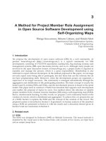
Before evaluating the effect of various operating parameters
on the performance of the adiabatic air dehumidifier, the validation of the developed analytical model should be achieved.
For this purpose, reliable experimental data from Moon et al.
[17] were selected. A plot digitizer program is used to extract
point data from Moon et al. [17]. The obtained inlet desiccant
0.001
Moon et. al. [17]
Present study
MRR, kgv/s
0.0008
0.0006
ma/ms=0.64, Ta1=30°C
ya1=0.02157 kgv/kgda,
Ts1=30°C.
0.34
0.36
After the validation of the analytical model with the experimental results, an extensive theoretical investigation was conducted to examine the effect of various operating parameters
on the adiabatic dehumidifier performance. The parametric
study includes the effect of air inlet humidity ratio and temperature, air to solution mass ratio, inlet desiccant concentration,
and temperature on the exit dehumidifier parameters. Table 2
provides the operating conditions considered for all cases in
the parametric analysis. The effect of each five parameter is
studied, while the other parameters are held constant.
Effect of inlet air humidity ratio
Validation of mathematical model
0.0004
0.32
concentrations from the plot digitizer are fed to the presented
model, and the results are shown in Fig. 2. According to these
results, good agreement between the experimental data of
Moon et al. [17] and the analytical results of present study is
achieved. In all cases, the most of predicted values for MRR
are higher than the experimental values, and the discrepancy
may be due to the assumptions made in the analysis. However,
the maximum deviation in MRR is +6.63% and À5.65%.
0.38
0.4
0.42
0.44
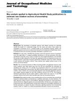
The effect of inlet air humidity ratio (ya1) on the moisture removal rate, dehumidifier effectiveness (MRR, ey; respectively),
and the exit parameters from the dehumidifier; air humidity ratio, air temperature, solution concentration, and solution temperature (ya2, Ta2, X2, and Ts2, respectively) is shown in Fig. 3.
As illustrated, when the inlet air humidity ratio is increased,
MRR, ya2, and Ts2 are increased, while ey, Ta2, and X2 show
no significant effect. To a great extent, the partial vapor pressure is the governing factor of the mass transfer occurs between process air and desiccant solution. As the inlet air
humidity ratio increases, the partial vapor pressure of air also
increases which in turn enhances the difference between the
partial vapor pressure in the inlet air-stream and that on the
desiccant solution surface resulting in an increase in the moisture absorbing capacity of desiccant solution. This increase
leads to high moisture removing capacity. On the other hand,
as ya1 is increased the increase in the numerator of Eq. (9) offsets, the increase in the denominator of the same equation results in slight decrease in the dehumidifier effectiveness. This in
turn increases the exit humidity ratio ya2. Increasing ya1 in turn
increases the enthalpy of air at the dehumidifier inlet which
rises the temperature of the solution at the exit. When ya1 is increased from 0.016 to 0.024 kgv/kgda, MRR, ya2, and Ts2 are
increased by 67.29%, 39.22%, and 13.39%, respectively.
Effect of inlet air temperature
X1, kgd/kgs
Fig. 2 Comparison of MRR at different X1 between present
study and Moon et al. [17].
Fig. 4 shows the effect of inlet air temperature (Ta1) on the
MRR, ey and the exit parameters from the dehumidifier; ya2,
Ta2, X2, and Ts2. As Ta1 is increased, both MRR and ey are
Liquid desiccant cross flow air dehumidifier
Operating conditions for the cases considered in the parametric analysis.
Cases
Ta1 (°C)
X1 (kgd/kgs)
Ts1 (°C)
0.64
1
1
1
1
0.25–2
0.02157
0.016–0.026
0.018
0.018
0.018
0.018
30
40
26–40
40
40
40
0.33–0.43
0.43
0.43
0.33–0.43
0.43
0.43
30
20
20
20
26–36
20
38
0.3
34
32
Ta2 &T s2 , oC
36
0.016
0.012
30
εy &
0.4
MRR
R
ya2
Ta2
Ts2
X2
Ey
0.02
MRR*10
MRR
10, kg v /s & ya2 , kgv /kgda
0.5
εy
& X 2 , kg d /kg s
0.6
( a/m
(m
ms=1
1, Ta11=40°°C ,T
Ts1=2
20°C
C, X1=0.43
= 3)
0.008
28
0.0
016
0.02
2
0.0
024
ya1, kgv/kgda
Fig. 3
Effect of ya1 on dehumidifier parameters (MRR, ey, ya2, Ta2, Ts2, X2).
MRR
ya2
Ta2
Ts2
X2
Ey
0.6
0.5
0.4
MRR*10, kg v /s & y a2 , kg v /kg da
0.7
& X 2 , kg d /kg s
2
3
4
5
6
7
ya1 (kgv/kgda)
εy
Fig.
Fig.
Fig.
Fig.
Fig.
Fig.
Inlet values for the parametric analysis
ma/ms
0.016
36
32
28
0.012
T a2 &T s2 , oC
Table 2
179
24
(ma/ms=1, ya1=0.018 kgv/kgda ,Ts1=20°C, X1=0.43)
0.3
0.008
24
28
32
36
40
20
Ta1, oC
Fig. 4
Effect of Ta1 on dehumidifier parameters (MRR, ey, ya2, Ta2, Ts2, X2).
180
M.M. Bassuoni
34
MR
RR
ya2
Ta
a2
Ts
s2
X2
2
Ey
y
0.4
4
MRR*10 kg
MRR*10,
k v/s
/ & y a2 , kg
k v/kg
/k da
εy & X2, kg d/kg s
0.5
5
0.013
32
0.012
30
Ta2 &T s2 , oC
0.014
0.6
6
0.011
(ma/ms=1, ya1=00.0188 kgv/kgda
d ,
0.0
01
28
Ts1=200°C, Ta1=40°C
C)
0.3
3
0.32
0.34
0.36
6
0.38
8
0.4
4
0.42
0.4
44
X1, kgd/kgs
Fig. 5
Effect of X1 on dehumidifier parameters (MRR, ey, ya2, Ta2, Ts2, X2).
decreased, but Ta2, ya2, and Ts2 are increased, while X2 has no
significant change. This may be explained as follows: as the inlet process air temperature is increased, the temperature of the
desiccant solution inside the dehumidifier is increased which in
turn increases Ts2, Ta2 and the partial vapor pressure on the
desiccant surface. When the desiccant surface vapor pressure
increases, the potential of the absorption process is decreased
causing air to become more humid (i.e., low Dya) and in turn
low MRR. On the other hand, the reduction in Dya is greater
than the decrease in (ya1 À yeq) which leads to low ey. When
Ta1 is increased from 26 °C to 40 °C, both MRR and ey are decreased by about 11.6% and 11.8%, respectively, but Ta2, ya2,
and Ts2 are increased by a percentage of 31.58%, 9.5%, and
6.8%, respectively.
Effect of inlet desiccant concentration
Fig. 5 shows the effect of inlet desiccant concentration (X1) on
the MRR, ey and the exit parameters from the dehumidifier;
ya2, Ta2, X2, and Ts2. When X1 is increased, MRR, Ts2, and
X2 are increased, but the dehumidifier effectiveness and Ta2
are slightly changed. When X1 increases, vapor pressure on
the desiccant surface is reduced leading to low ya2 which in
turn increases MRR. As shown from Table 2, the inlet air temperature is higher than the inlet temperature of the desiccant
solution resulting in high Ts2. Both ya2 and yeq are decreased
but at different rates which means that the numerator of Eq.
(9) is to some extent smaller than its denominator; so, ey is
slightly reduced. Increasing X1 from 0.33 to 0.43, MRR, Ts2,
0.016
0.014
44
40
0.012
36
0.01
Ta2 &Ts2, o C
0.6
MRR*10, kgv /s & ya2, kgv /kgda
εy &X2, kgd/kgs
0.8
MRR
ya2
Ta2
Ts2
X2
Ey
(ma/ms=1, ya1=0.018 kgv/kgda,
X1=0.43, Ta1=40°C)
0.008
32
0.4
0.006
28
32
36
Ts1, oC
Fig. 6
Effect of Ts1 on dehumidifier parameters (MRR, ey, ya2, Ta2, Ts2, X2).
Liquid desiccant cross flow air dehumidifier
181
0
0.5
MRR
R
ya2
Ta2
Ts2
X2
Ey
0.02
40
0
Ta2 &Ts2, oC
εy &X2, kgd/kgs
0
0.6
50
0
10, kgv/s & yaa22, kgv/kgda
MRR*10,
MRR
0
0.7
0.01
30
0
0
0.4
(X1=0.443, ya1=00.018 kgv/kgdaa, Ts1=20°°C, Ta1=440°C)
0
20
0
0
0.5
5
1
1.5
2
ma /m
ms , kga /kgs
Fig. 7
Effect of ma/ms on dehumidifier parameters (MRR, ey, ya2, Ta2, Ts2, X2).
and X2 are increased by 39.13%, 10.33%, and 30%, respectively. On the other hand, both ya2 and ey are decreased by a
percentage of 15.64% and 1.66%, respectively.
Effect of inlet desiccant temperature
Fig. 6 shows the effect of inlet desiccant temperature (Ts1) on
the MRR, ey and the exit parameters from the dehumidifier;
ya2, Ta2, X2, and Ts2. When Ts1 is increased, ya2, Ta2, ey, and
Ts2 are increased, however, the MRR is decreased and X2 is
unaffected. Increasing Ts1 increases the vapor pressure on
the desiccant surface which in turn decreases the moisture
absorption from the process air, and hence, MRR is decreased
but ya2 increases. When Ts1 increases, the difference between
(ya1 À ya2) is more than that of (ya1 À yeq) which in turn increases ey (see Eq. (9)). Increasing Ts1 from 26 °C to 36 °C results in increasing ya2, Ta2, ey, and Ts2 by 28.61%, 16.92%,
22.88%, and 12.2%, respectively, but MRR is decreased by
about 48.92%.
Conclusions
Air dehumidification by using CaCl2 desiccant solution in a
cross-flow liquid desiccant dehumidifier is studied by proposing a simple analytical model. The developed analytical model
shows an excellent agreement with the available experimental
data from Moon et al. [17]. Thus, for a detailed study of the
absorption process, this model gives accurate performance prediction, minimizing the use of calculation and assumptions.
Operating variables found to have the greatest impact on the
dehumidifier performance. The following conclusions from
the analytical results can be summarized: The moisture removal rate is decreased with increasing both air inlet temperature and desiccant temperature while increases with increasing
ma/ms, X1, and ya1. The dehumidifier effectiveness increases
with the increase of Ts1, while it decreases with the increase
of Ta1 and ma/ms. Increasing Ta1, Ts1, and ya1 results in higher
ya2, however, low exit humidity ratio is obtained at lower inlet
desiccant concentration. The exit desiccant solution concentration remains unaffected by changing different operating parameters except X1.
Effect of air to solution mass ratio
Conflict of interest
Fig. 7 shows the effect of air to solution mass ratio (ma/ms) on
the MRR, ey and the exit parameters from the dehumidifier;
ya2, Ta2, X2, and Ts2. When ma/ms is increased, both MRR
and Ts2 are increased, but ey is decreased, while Ta2 and ya2
are slightly increased, however, X2 is slightly decreased. The
potential capacity of the desiccant solution to carry over moisture from the process air is reduced by increasing ma/ms results
in higher outlet ya2 which in turn reduces ey. Increasing the
mass flow rate of air leads to high heat capacity of air compared to solution which offset the temperature increase in
air-stream. Increasing ma/ms by 400% results in an increase
in both MRR and Ts2 by 611% and 81.6%, respectively. On
the other hand, ey is decreased by about 11.1%.
The author has declared no conflict of interest.
References
[1] Li Z, Liu XH, Jiang Y, Chen XY. New type of fresh air
processor with liquid desiccant total heat recovery. Energy Build
2005;37:587–93.
[2] Potnis SV, Lenz TG. Dimensionless mass-transfer correlations
for packed-bed liquid-desiccant contactors. Ind Eng Chem Res
1996;35(11):4185–93.
[3] Factor HM, Grossman G. A packed bed dehumidifier/
regenerator for solar air conditioning with liquid desiccants.
Solar Energy 1980;24:541–50.
182
[4] Gandhidasan P, Kettleborough CF, Ullah MR. Calculation of heat
and mass transfer coefficients in a packed tower operating with a
desiccant-air contact system. Solar Energy 1986;108(2):123–8.
[5] Ertas A, Anderson EE, Kavasogullari S. Comparison of mass
and heat-transfer coefficients of liquid-desiccant mixtures in a
packed-column. J Energy Resour-ASME 1991;113(1):1–6.
[6] Stevens DI, Braun JE, Klein SA. An effectiveness model of
liquid desiccant system heat/mass exchangers. Solar Energy
1989;42(6):449–55.
[7] Ren CQ, Jiang Y, Zhang YP. Simplified analysis of coupled heat
and mass transfer processes in packed bed liquid desiccant-air
contact system. Solar Energy 2006;80(1):121–31.
[8] Lu ZF, Chen PL, Zhang X. Approximate analytical solution of
heat and mass transfer processes in packed-type cross-flow
liquid desiccant system and its experimental verification. J
Tongji Univ. 2001;29(2):149–53.
[9] Liu XH, Jiang Y, Qu KY. Analytical solution of combined heat
and mass transfer processes of cross-flow dehumidifier using
liquid desiccant. Taiyangneng Xuebao/Acta Energy Solar Sin.
2006;27(8):774–81.
[10] Liu XH, Jiang Y, Xia J, Chang X. Analytical solutions of coupled heat
and mass transfer processes in liquid desiccant air dehumidifier/
regenerator. Energy Convers Manage 2007;48:2221–32.
[11] Dai YJ, Zhang HF. Numerical simulation and theoretical
analysis of heat and mass transfer in a cross flow liquid
desiccant air dehumidifier packed with honeycomb paper.
Energy Convers Manage 2004;45(9–10):1343–56.
M.M. Bassuoni
[12] Khan AY, Sulsona FJ. Modeling and parametric analysis of
heat and mass transfer performance of refrigerant cooled
liquid desiccant absorbers. Int J Energy Res 1998;22(9):
813–32.
[13] Liu XH, Jiang Y, Qu KY. Heat and mass transfer model of
cross-flow liquid desiccant air dehumidifier/regenerator. Energy
Convers Manage 2007;48(2):46–54.
[14] Liu XH, Zhang Y, Qu KY. Experimental study on mass transfer
performance of cross-flow dehumidifier using liquid desiccant.
Energy Convers Manage 2006;47(15–16):2682–92.
[15] Koronaki IP, Christodoulaki RI, Papaefthimiou VD, Rogdakis
ED. Thermodynamic analysis of a counter flow adiabatic
dehumidifier with different liquid desiccant materials. Appl
Therm Eng 2013;50(1):361–73.
[16] Davoud B, Meysam S. An analytical solution for air
dehumidification by liquid desiccant in a packed column. Int
Commun Heat Mass 2009;36:969–77.
[17] Moon CG, Bansal PK, Sanjeev J. New performance data of a
cross flow liquid desiccant dehumidification system. Int J Refrig
2009;32:524–33.
[18] Adnan AK, Moustafa ME, Omar MA. Proposed energy
efficient air-conditioning system using liquid desiccant. Appl
Therm Eng 1996;16(10):791–806.
[19] Gad HE, Hamed AM, El-Sharkawy II. Application of a solar
desiccant/collector system for water recovery from atmospheric
air. Renew Energy 2001;22:541–56.