Analyses on the effect of magnetic induction attenuation on the current distribution in a faraday MHD generator
Bạn đang xem bản rút gọn của tài liệu. Xem và tải ngay bản đầy đủ của tài liệu tại đây (671.28 KB, 10 trang )
TAẽP CH PHAT TRIEN KH&CN, TAP 16, SO K2- 2013
ANALYSES ON THE EFFECT OF MAGNETIC INDUCTION ATTENUATION ON
THE CURRENT DISTRIBUTION IN A FARADAY MHD GENERATOR
Le Chi Kien
Ho Chi Minh City - University of Technical Education
(Manuscript Received on December 24th, 2012, Manuscript Revised April 24th, 2013)
ABSTRACT: This paper examines the dependence of the attenuation of magnetic induction on
the current distribution etc. in the exit regions of the Faraday type non-equilibrium plasma MHD
generator by a two-dimensional calculation. The numerical analyses are made for an example of the
cesium-seeded helium. As a result, a reasonable magnetic induction attenuation can make the
distribution of current very uniform near the exit region of generator channel and has little influence on
the current distribution in the middle part of generator, and the output electrodes can be used without
great ballast resistors. Also the inside resistance of the exit region and the current concentration at the
exit electrode edges decrease with the attenuation of magnetic flux density. By the author's examination,
it is made clear that the exit electrodes of the diagonal Faraday type non-equilibrium plasma MHD
generator should be arranged in the attenuation region of the magnetic induction, since arranging them
in this region becomes useful for the improvement of the electrical parameters of generator.
Keywords: Numerical calculation, MHD generator, diagonal type, ballast resistance, twodimensional analysis.
1. INTRODUCTION
Accordingly,
by
a
two-dimensional
Already it has been ascertained that the
analysis, the author has investigated the
performance characteristics of a diagonal type
electrical characteristics in the central part of
non-equilibrium plasma generator can be well
the diagonal type non-equilibrium plasma
approached to those of the Faraday type one by
generator duct as described in [3], etc.
the quasi one-dimensional MHD theory [1,2].
Moreover, in the end regions of the MHD
However, though this theory is convenient for
generators there arise the so-called end effects,
us to grasp the outline of the generator
and
characteristics, it is very difficult to treat
characteristics of the generators.
they
degrade
the
total
electrical
accurately the effects of the spatial non-
Hence, up to now the end effects in the
uniformity of the working gas plasma in the
Faraday type generator have been analyzed in
generator duct cross section by the above
fair detail [4-6]. On the other hand, the end
theory.
effects in the diagonal type have been only a
little discussed [7-9]. Therefore, the author has
investigated
some
influences
of
the
Trang 63
Science & Technology Development, Vol 16, No.K2- 2013
arrangement of the output electrodes and the
In order to evaluate the current distribution
attenuation of the magnetic induction along the
in the generator duct, we introduce the
generator duct on the current and potential
conventional stream function defined by
distributions etc. near the entrance and exist of
J x y , J y x
(1)
the diagonal type MHD duct when the physical
quantities in the duct are assumed to be
where Jx and Jy are the x and y components of
uniform, and shown that the variation of the
current density, and the z component Jz is
arrangements of output electrodes has little
assumed not to exist.
effect on the current distribution etc. [10]
In this paper the author studies the end
plasma
generator
by
a
the boundary and subsidiary conditions are
A'1
Anode Ai
A'i
y
two-dimensional
analysis. In section 2, the basic equations and
A1
E2
E1
effects in the diagonal type non-equilibrium
Insulator
Rb
I
h
z
(B)
x
(u)
introduced, then, are shown configurations of
the gas velocity and the applied magnetic
C1
induction that are adopted in the present paper.
C'1
c
Ci
C'i
Cathode Cn
C'n
s
In section 3, by the numerical calculations are
investigated the influences of the attenuation of
Figure 1. Coordinate system and generator duct
the magnetic induction on the current and
geometry
potential distributions, the internal resistance
Then, it is assumed that the magnetic
etc. in the end regions of the generator.
induction and the gas velocity have only the z
2. BASIC EQUATIONS
component B and the x component u,
2.1. Basic equations for current distribution
respectively, from the Maxwell equations and
In the analysis of end effects in a diagonal
type MHD generator, it is assumed that the
electric quantities, such as the current, electric
field etc., vary with x and y, where x and y are
the coordinates as shown in Fig. 1, and that the
gas velocity and temperature depend on only y
according to Eqs. (9) and (10) which will be
presented later, and that the pressure is kept
constant.
Trang 64
the generalized Ohm's law which are given in
Eqs. (1) and (2) in Ref. [3], we can derive the
following partial differential equation:
2 P x Q y R
(2)
where
TAẽP CH PHAT TRIEN KH&CN, TAP 16, SO K2- 2013
P / / / x / / y
Q / / / y / / x
R / { p e / y / en e / x
p e / x / en e / y
u B / x }
1 i
where E is the electric field intensity vector, ds
the line element vector of an optional integral
path from Ai to Ci, and Vi the potential
(3)
difference between Ai and Ci.
As the current which runs through an
arbitrary surface Si crossing the insulating wall
in which e is the electron charge, pe =nekTe the
surfaces A'i and C'i is equal to the load current
electron partial pressure, ne the electron
I, the second subsidiary condition is written as
density, k Boltzmann's constant, Te the electron
SJdS
I , i=1, 2, , n
(7)
i
temperature, the Hall parameter for electron,
i the Hall parameter for ion, and the scalar
where dS is the element vector of the surface
electrical conductivity of the plasma. In
Si.
addition, since , , ne and Te are given in Ref.
Lastly, let us assume that the electric
[3], we omit the explanation for them in this
quantities vary periodically in the period of the
paper.
electrode pitch s along the gas flow behind the
2.2. Boundary and subsidiary conditions
n-th electrode pair An and Cn. Then the
First, the boundary condition on the
by
electrode surfaces is
Ex 0
J (x s) J( x )
(4)
where Ex is the x component of electric field.
The one on the insulating wall surfaces is
Jy 0
(5)
(8)
By Eq. (1), the Eq. (8) is transformed into
( x s) ( x ) I (yn )
(8)
where I (yn ) is the current flowing into An.
Using Eq. (1), these conditions (4) and (5)
are transformed to
The current distributions in the diagonal
type generator can be found by numerically
/ y / x p e / x / en e 0 (4)
const
condition for the current density J(x) is given
solving Eq. (2) under the conditions (4)~(7)
and (8) (see section 3).
(5)
Next, in the diagonal type generator, the
2.3. Calculation of potential
potential difference must be zero between the
When Eq. (2) is numerically solved under
anode Ai and cathode Ci which are shorted each
the conditions (4)~(7) and (8), the electric
other as shown in Fig. 1. Therefore, the first
field E at the optional point can be evaluated by
subsidiary condition is obtained as
Eq. (1) and the generalized Ohm's law, with the
Vi
Ci
A
i
Eds 0 , i=1, 2, , n
(6)
obtained numerical solution of . Then the
potential at any point can be calculated by the
Trang 65
Science & Technology Development, Vol 16, No.K2- 2013
numerical line integration of E along an
the end regions of the diagonal type generator,
arbitrary integral path from a reference point to
we assume that the intensity of B is constant in
the considered point.
the central region and decreases linearly from
2.4.
Gas
velocity
and
temperature
regions of the generator. In this connection in
distributions
As assumed in section 2, the velocity u has
only the x component u, and u and T vary only
in the y direction according to the following
this numerical analysis, the author assumes the
six configurations of B as plotted in Fig. 2,
where g is the gradient of B and j=5.
3.
relation [11]
u / u 0 4 y / h (1 y / h )m
NUMERICAL
METHOD
FOR
SUBSIDIARY CONDITIONS
(9)
In a diagonal generator, the solution of Eq.
n
( T T w ) /( T0 Tw ) 4 y / h (1 y / h )
(10)
respectively, where h is the duct height, u0 and
T0 are the gas temperature and velocity at the
center of flow, namely y=h/2 and Tw is the wall
temperature.
4
the left edge of the j-th electrode in the end
(3) is required to satisfy the two subsidiary
conditions (6) and (7). From Eqs. (1) and (7),
we can derive the following equation:
iA iC I w , i=1, 2,…, n (11)
where iA and iC are the values of on the
insulating
g=0.0
wall
surfaces
Ai
and
Ci
B [T]
respectively, and w is the duct width in the z
2.0
direction.
4.0
First, if the values of I and w are assumed
2
6.0
8.0
and iA are given plausible values, the values
10.0
1 2 3 4 5 6 7 8
Electrodes
of iC are decided by Eq. (11). When Eq. (2)
is digitally solved with these values of iA
and iC and the appropriately assumed values
Figure 2. Configuration of applied magnetic
induction
of u, and , we can obtain the numerical
solution of . By applying the solution to Eq.
2.5. Configuration of Applied Magnetic
(1) and the generalized Ohm's law, we can find
Induction
the values of Ex and Ey. Further, by substituting
For effective use of the applied magnetic
the values of Ex and Ey into the integral in Eq.
flux density B, the MHD generator duct may be
(6), we can decide the value of Vi. Then the
arranged in the attenuation region of B. So in
value of Vi obtained is not necessarily equal to
order to investigate the influence of the
zero.
configuration of B on the current distribution in
Trang 66
TAẽP CH PHAT TRIEN KH&CN, TAP 16, SO K2- 2013
Let us consider the resistance between the
R i h
h 0 . 2 , s 0 . 1, w 0 . 1, c 0 . 06 m
(14)
u 0 2000 m / s , m n 1 7 , B 0 4 or 5 T
5, s 0 .3 %
T0 1800 K , Tw 1600 K , p 5 atm
electrodes Ai and Ci
i cw cos( ), i=1, 2,, n
(12)
where h, c and are the duct height, the
electrode width and the angle of inclination to
the y axis of the lines joining the equipotential
electrodes, respectively, and we assume that an
imaginary current defined by
where s is the seed fraction of Cs, B0 the
magnetic induction in the central region of
generator duct, and the collision loss factor.
These conditions are assumed with respect to a
generator of the pilot plant [13]. The load
I i Vi R i , i=1, 2,, n
(13)
current I is assumed to flow equally into two
flows through the resistance Ri. To make Vi
output electrodes E1 and E2 through a ballast
zero, it is needed to flow the inverse current Ii
resistance Rb defined by (see Fig. 1)
through R i. Then it is required to increase by Ii
the value of
w( iA1
iA ),
R
b
which gives the
E2
E
Eds
(I / 2)
(15)
1
4.2. Calculation Results
current running into the anode Ai.
Again beginning with the new modified
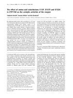
In Figs. 3a~c, the current distributions are
values of iA , we must repeat the above
plotted in the case of g=0, 6 and 10T/m,
mentioned calculation process.
When Vi
becomes adequately small after the many
repetitions of the above mentioned process, at
last we can obtain the satisfactory numerical
solution of .
respectively, B0=4T and I=70A, where the
contour interval of current streamlines is 1/20
of the load current I. In the figures, J el=
0.583A/cm2, =1.84 mho/m, =2.01 and
crit=2.48, where Jel is the average current
density on the output electrodes, and are
In connection, the other parts of numerical
calculation processes are explained in Ref.
[12].
4. NUMERICAL CALCULATION
4.1. Numerical Conditions
the average electrical conductivity and Hall
parameter in the center of flow, respectively,
crit is the critical Hall parameter [14].
Figure
3(a)
shows
that
the
current
concentration at the edges of the output
Numerical analysis is carried out for the
electrodes is very intensive when B does not
diagonal type MHD generator with the cesium
attenuate. On the other hand, Figs. 3(b) and (c)
seeded helium in non-equilibrium ionization in
indicate that the concentration weakens as the
which
attenuation of B increases, since becomes
small in the area suffering a spatial reduction of
B. Also it is seen that the current flowing into a
Trang 67
Science & Technology Development, Vol 16, No.K2- 2013
diagonally connected electrode pair reduces
electrodes are disposed in the region of the
with increasing the gradient of the magnetic
attenuating magnetic induction [5], and that
induction in the entrance region of duct, for
arranging the output electrodes within the
instance, the currents of about 60, 25 and 15%
attenuation region of B does not have a great
of I flow into C, when g=0, 6 and 10T/m,
influence on the current distribution in the
respectively. Also the figures denote that the
central part of generator duct.
eddy current is not induced when the output
Rb
E1
E2
C1
C2
A1
C3
A2
A3
A4
A5
A6
C4
C5
C6
C7
C8
(a) g=0, B0=4
Rb
E1
E2
C1
C2
A1
C3
A2
A3
A4
A5
A6
C4
C5
C6
C7
C8
(b) g=6, B0=4
Rb
E1
C1
E2
C2
A1
C3
A2
A3
A4
A5
A6
C4
C5
C6
C7
C8
(c) g=10, B0=4
Figure 3. Current distributions
Trang 68
TAẽP CH PHAT TRIEN KH&CN, TAP 16, SO K2- 2013
4
g=0
2
[kV]
2
4
6
8
1
10
0
Ri/Ri0, Rb/Rb0, Jpeak/Jel(ì10)
1.2
3
1.0
Ri/Ri0
0.8
0.6
Jpeak/Jel
Rb/Rb0
0.4
0.2
0
E1 E2 A1 A2 A3 A4 A5 A6 A7 A8
Figure 4. Variation of potential difference
0
2
4
6
g [T/m]
8
10
Figure 5. Influence of g on Ri/R i0, Rb/Rb0 and J peak/J el
when B0 =4
for B0 =4
Next, Fig. 4 shows the variation of the
where V0 and V are no-load and load potential
potential difference between the electrode pairs
difference between the output electrode E1 and
A1-C 1~A8-C8 and the electrode E1. From the
the n-th electrode, respectively, and Jpeak is the
figures it is seen that the relatively large
maximum current density on the output
potential difference arises between the two
electrodes. In this connection, Jpeak/Jel=1
output electrodes E1 and E2 when B does not
means the state of no current concentration and
attenuate, namely g=0. On the other hand, the
Jpeak/Jel>>1
potential difference become smaller as g
concentration at an electrode edge.
becomes larger, it almost vanishes for g=6, and
the inverse difference appears for g>7. Also
Fig. 4 denotes that the potential differences in
the central part of generator duct are little
influenced by the decrease of the magnetic
induction.
does
the
intensive
current
Now Fig. 5 shows the variations of R i/Ri0,
Rb/Rb0 and Jpeak/Jel by g, where Ri0 and Rb0 are
Ri and Rb for g=0, respectively. From the
figure, it is seen that Ri decreases with g, for
instance the value of Ri for g=6.0 becomes
about 80% of the one of Ri0, and that Jpeak/Jel
Next, for estimation of the end effects of
decreases from g=0 to 8T/m, reaches the
the generator, the author evaluates the internal
minimum value 1.90 and increases again. This
resistance Ri of the end regions and the grade
fact shows that the current concentration at the
of the current concentration on the output
edges of the output electrodes is almost
electrodes given by the relations
diminished
R i V0 V I
J peak
J
el
1
(16)
(17)
arranging
when
the
g=8T/m.
output
Accordingly,
electrodes
in
the
attenuation area of the magnetic flux density is
Trang 69
Science & Technology Development, Vol 16, No.K2- 2013
useful to guard the output electrodes. Also Fig.
electrodes will require large ballast resistors
5 tells that Rb/Rb0 decreases with g, becomes
when B does not attenuate or exceeds 8, but
almost zero for g=6.5 and then increases with
they can be used without large ballast resistors
g. Therefore, it is shown that many output
in the range of g=6~7T/m.
Rb
E1
E2
C1
C2
A1
A2
A3
A4
A5
A6
C3
C4
C5
C6
C7
C8
Figure 6. Current distribution for g=6 and B0=5
In Fig. 6, the current distribution is plotted
when
g=6T/m,
B0=5T
and
distribution very uniform near the end
I=150A,
region of generator duct, both when the
Jel=1.25A/cm , =2.85mho/m, =2.48 and
streamer is not induced and when it is
crit=1.90. The figure indicates that the streamer
induced in the central region.
2
is induced in the central part of generator,
while
the
current
distribution
2.
becomes
Disposing the output electrodes within the
attenuation area of magnetic flux density
successively uniform as B attenuates along the
has
generator duct and the current concentration is
distribution in the central part of generator
almost swept away near the output electrodes.
duct.
Therefore it is seen that arranging the output
3.
little
influence
on the
current
When the output electrodes are disposed
electrodes within the attenuating region of B is
in the region with a suitably reduced
effective for the case where the streamer is
magnetic flux density, the potential
generated in the central region of generator
difference and the ballast resistance
duct, too.
between two output electrodes become
5. CONCLUSIONS
very small. Accordingly it is thought that
many output electrodes can be used
The main conclusions derived from the
without large ballast resistors.
above described numerical calculation are as
follows:
1.
4.
The internal resistance in the end region
A suitable distribution of the magnetic
of the generator duct decreases as the
flux density can make the current
magnetic flux density attenuates.
Trang 70
TẠP CHÍ PHÁT TRIỂN KH&CN, TẬP 16, SỐ K2- 2013
5.
The current concentration at the edges of
equilibrium plasma MHD generator should be
output electrodes can be fairly eliminated
arranged in the region of the attenuating
by attenuating magnetic flux density.
magnetic flux density, since arranging them in
As mentioned above, it is made clear that
the region of the decreasing magnetic flux
the output electrodes of the diagonal type non-
density become useful for the improvement of
the electrical characteristics of the generator.
PHÂN TÍCH ẢNH HƯỞNG CỦA SỰ SUY GIẢM CẢM ỨNG TỪ ĐẾN SỰ PHÂN BỐ
DỊNG ĐIỆN TRONG MÁY PHÁT ĐIỆN TỪ THỦY ĐỘNG LOẠI FARADAY
Le Chi Kien
Ho Chi Minh City - University of Technical Education
TĨM TẮT: Bài báo nghiên cứu ảnh hưởng của sự suy giảm của cảm ứng từ đến sự phân bố
dòng điện trong vùng phía cuối của máy phát điện Từ thuỷ động loại điện cực chéo dùng plasma khơng
cân bằng bằng phân tích hai chiều. Những tính tốn số đã được thực hiện cho trường hợp khí làm việc
hê-li được cấy thêm xê-zi. Kết quả là một sự suy giảm phù hợp của cảm ứng từ có thể tạo ra sự phân bố
dòng điện rất đồng nhất gần khu vực cuối của ống dẫn máy phát điện, và ảnh hưởng nhỏ đến phân bố
dòng điện ở khu vực giữa, và điện cực đầu ra có thể được dùng mà khơng cần điện trở cân bằng lớn.
Điện trở nội của vùng cuối và sự tập trung dòng điện tại điện cực đầu ra cũng giảm cùng với sự suy
giảm của mật độ từ thơng. Theo như khảo sát được từ bài báo, rõ ràng là điện cực đầu ra của máy phát
điện Từ thuỷ động loại điện cực chéo dùng plasma khơng cân bằng nên được sắp xếp trong khu vực suy
giảm của cảm ứng từ bởi vì việc sắp xếp này sẽ trở nên hữu ích trong việc cải thiện những thuộc tính
điện của máy phát.
REFERENCES
[1].
[2].
Y. Hamada, K. Amazawa, S. Murakawa,
H. Yamaguchi, Y. Hisazumi, H. Asano, H.
H. Kitayama, M. Nabeshima, H. Takata,
Morita, T. Hori, T. Matsumoto, T. Abiko,
Study on Operation Characteristics and
A
of
Performance Evaluation of Residential
Cogeneration for the Local Community,
Combined Heat and Power System, JSER
JSME Journal of Power and Energy
27th International Conference on Energy,
Systems, 2, 3, 1085-1095 (2008).
Economy, and Environment, 7-1, 453-458
New
Heat
Supply
System
(2011).
Trang 71
Science & Technology Development, Vol 16, No.K2- 2013
[3].
S.
Mori,
[5].
Akatsuka,
M.
Suzuki,
Separation by Plasma Chemical Reactions
Channel,
in Carbon Monoxide Glow Discharge,
Management, 42, 8, 963-966 (2001).
of
Nuclear
Science
and
Inui,
Proposed
Energy
H.
Indian
Conversion
Ito,
T.
Ishida,
MHD
and
Two
Dimensional Simulation of Closed Cycle
V.A. Bityurin, MHD Electrical Power
Disk MHD Generator Considering Nozzle
Generation in a T-Layer Plasma Flow,
and Diffuser, Energy Conversion and
IEEE Transactions on Plasma Science, 28,
Management,
3, 1020-1028 (2000).
(2004).
45,
13-14,
1993-2004
S.M. Aithal, Shape Optimization of a
[11]. Y. Gelfgat, J. Krūminš, B.Q. Li, Effects of
MHD Generator Based on Pressure Drop
System Parameters on MHD Flows in
and
Rotating Magnetic Fields, Journal of
Power
Output
Constraints,
Crystal Growth, 210, 4, 788-796 (2000)
[12]. E. M. Braun, R. R. Mitchell, A. Nozawa,
S.M. Aithal, Characteristics of Optimum
D. R. Wilson, F. K. Lu, J. C. Dutton,
Power Extraction in a MHD Generator
Electromagnetic Boundary Layer Flow
with Subsonic and Supersonic Inlets,
Control
Energy Conversion and Management, 50,
Conductive Nanoparticle Seeding, 46th
3, 765-771 (2009).
Aerospace Sciences Meeting and Exhibit,
M. Anwari, N. Sakamoto, T. Hardianto, J.
AIAA Paper 2008-1396 (2008).
Kondo, N. Harada, Numerical Analysis of
Magnetohydrodynamic
Facility
Development
Using
[13]. Lingen Chen, Jianzheng Gong, Fengrui
Accelerator
Sun, Chih Wu, Heat Transfer Effect on the
Performance with Diagonal Electrode
Performance of MHD Power Plant, Energy
Connection,
Conversion and Management, 43, 15,
Management,
Energy
47,
Conversion
13-14,
and
1857-1867
(2006).
[8].
[10]. Y.
of
Technology, 39, 6, 637-646 (2002).
47, 6, 778-786 (2008).
[7].
B.S. Bhadoria, A. Chandra, Transient
Analysis
International Journal of Thermal Sciences,
[6].
[9].
Numerical Analysis of Carbon Isotope
Journal
[4].
H.
2085-2095 (2002).
[14]. E. Sawaya, N. Ghaddar, F. Chaaban,
Motoo Ishikawa, Fumiki Inui, Juro Umoto,
Evaluation of the Hall Parameter of
Fault Analysis of a Diagonal Type MHD
Electrolyte Solutions in Thermosyphonic
Generator Controlled with Local Control
MHD Flow, International Journal of
Circuit,
Engineering Science, 40, 18, 2041-2056
Energy
Conversion
Management, 40, 3, 249-260 (1999).
Trang 72
and
(2002).