Nonlinear optical tweezers as an optical method for controlling particles with high trap efficiency
Bạn đang xem bản rút gọn của tài liệu. Xem và tải ngay bản đầy đủ của tài liệu tại đây (3.21 MB, 18 trang )
Communications in Physics, Vol. 29, No. 3 (2019), pp. 197-214
DOI:10.15625/0868-3166/29/3/13733
NONLINEAR OPTICAL TWEEZERS AS AN OPTICAL METHOD FOR
CONTROLLING PARTICLES WITH HIGH TRAP EFFICIENCY
HO QUANG QUYa,b,†
a Ho
Chi Minh University of Food Industry, 140 Le Trong Tan, Tan Phu, Ho Chi Minh City
of Military Science and Technology, 17 Hoang Sam, Cau Giay, Hanoi
b Academy
† E-mail:
Received 5 April 2019
Accepted for publication 19 June 2019
Published 15 August 2019
Abstract. Optical tweezers have been seen as an essential tool for manipulating dielectric microparticles and nanoparticles thanks to its non-contact action and high resolution of optical
force. Up to now, there has been a lot of optical tweezers applications in the fields of biophysics,
chemistry, medical science and nanoscience. Recently, optical tweezers have been theoretically
and experimentally developed for the nano mechanical characterization of various kinds of biological cells. The configuration of optical tweezers has been day after day improved to enhance
the trapping efficiency, spatial and temporal resolution as well as to ease the control of trapped
objects. In common trend of optical tweezers improvements, we will discuss in detail several configurations of nonlinear optical tweezers using nonlinear materials as the added lens. We will also
address the advantages of nonlinear optical tweezers, such as enhancement of optical efficiency,
reduction of trapping region, and simplification in controlling all-optical method. Finally, we will
present discussions about the specific properties of nonlinear optical tweezers used for stretch
DNA molecule as example and an idea to improve nonlinear optical tweezers using thin layer of
organic dye proposed for going time.
Keywords: nonlinear physics; biophysics; optical tweezers, nonlinear optical tweezers,
DNA molecule.
Classification numbers: 42.65.Wi; 42.79.-e; 87.80.-y.
c 2019 Vietnam Academy of Science and Technology
198
NONLINEAR OPTICAL TWEEZERS AS AN OPTICAL METHOD FOR CONTROLLING PARTICLES . . .
I. INTRODUCTION
Up to now, the optical tweezers (OT) has been becoming an efficient support tool widely
applied in physics, chemistry, medical science, nanoscience and biology [1, 2]. The idea of OT
was first reported in 1970 by Arthur Ashkin [3], a former Bell Laboratories researcher awarded the
2018 Nobel Prize in Physics “for the optical tweezers and their application to biological systems”
on October 2nd , 2018. Two main parts of OT are the laser source and high numerical aperture
(NA) microscope objective creating a laser beam with high spatial gradient of intensity, i.e., the
Gaussian beam, commonly. Irradiated by the Gaussian beam, the dielectric particle having refractive index n p larger than that of its surrounding fluid ns f (m = n p /ns f > 1) should be pulled into the
center of beam waist. Meanwhile, irradiated by the hollow Gaussian beam, the dielectric particle
with refractive index smaller than that of its surrounding fluid (m = n p /ns f < 1) should be pulled
into the center of dark region. So the optical tweezers are used to trap and hold the dielectric particles, and to manipulate (or to control) them in space of embedding fluid [4–6]. For the diversified
applications [7, 8] there is a lot of methods used to trap and control trapped dielectric particles as:
laser beam scanning used rotation system of mirrors [1], laser beam scanning used acousto-optical
deflector [9], focused laser controller using intelligent electro-mechanical or opto-mechanical system with help of the computer, etc. [4, 10–12]. To control trapped dielectric particles in 2D or
3D space, all mentioned methods need two facts, at least [13]. Lately, to avoid the complexity of
opto-mechanical system, an all-optical method to control dielectric particles in nonlinear embedding fluid by tuning of laser power is proposed [6] based on the Kerr effect [14–16]. However,
this proposal for optical tweezers meets a difficulty that the embedding fluid could not immediately change suitable to other dielectric particles due to ratio of their refractive indexes. Referring
to idea of this method, the acousto-optical tweezers whose operation is based on the nonlinear
response of refractive index of acousto-optical material to intensity of the acoustic wave, are proposed and investigated to control dielectric particles in 2D or 3D space of embedding fluid [17].
Although our proposals could be really used to design optical tweezers, they need a high intensity
of acoustic wave, which is the difficult problem in experiment.
As well-known, since the nonlinearity of convenient fluid and interesting particles are very
low, for example the nonlinear refractive index of water, polystyrene and silica is just nw =
2.7 × 10⁻²⁰ m2 /W [18], n p = 5.9 × 10⁻¹⁷ m2 /W [19] and ns = 2.0 × 10⁻²⁰ m2 /W [20], respectively,
so the nonlinear effect in OT should be observed only if using the high-repetition ultrafast pulsed
laser [21–23]. Consequently, the nonlinear effect is very weak and then practically to enhance optical trap efficiency (OTE) it needs a high laser intensity [6]. Fortunately, there is a lot of organic
dyes with high nonlinearity as Diclothane Polimetin [24] with nDp ≈ 5.5 × 10⁻⁸ cm2 /W, Acid blue
with nAb ≈ 1 × 10⁻¹⁰ m2 /W [25], Mercurochrome with nMer ≈ 1 × 10⁻¹¹ m2 /W at laser wavelength
of 532 nm [26], and Acid Green with nAg ≈ 1 × 10⁻¹¹ m2 /W at laser wavelength of 635 nm [27].
All mentioned organic dyes are not only in solvent, but can be also chemically accumulated in
the glass plate with thickness below millimeter, which has been used to observe the nonlinear
refraction as well as laser limiter [28]. The high nonlinearity organic dyes have given us an opportunityto design a compact nonlinear optical tweezers (NOTOD), in which a thin layer of organic
dye combined with the microscope objective replaces the nonlinear surrounding fluid to play the
nonlinear lens [14, 15]. Proposed NOTOD can be used to longitudinally control particles embedded in the linear surrounding fluid chemically suitable to the bio-subjects [29]. Using NOTOD,
HO QUANG QUY
199
the OTE is remarkably enhanced in comparison with the convenient linear OT [30]. Moreover,
by NOTOD the trapped particles will be controlled not only by all-optical method [31], but the
difficulties of choice of the nonlinear surrounding fluid chemically suitable to bio-subjective as the
living cell can also be overcome.
In this paper, we present the usefulness of Kerr effect in optical trap, relative theoretical
analysis and some of NOT’s configurations in progress. Then, we numerically investigate and
discuss on some advantages of NOT for the control trapped and stretch DNA molecule by tuning
laser power, and the configuration of NOTOD suitable to the different kind of DNA molecules.
II. TRAP PRINCIPLES
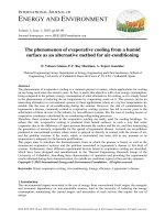
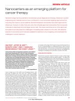
Fig. 1. Optical force due to photons meeting a refracting object.
Let us consider a micro-particle irradiated by the laser beam consisting of N photons which
have the momentum p = h¯ k. After interacting with the particle, the momentum of photons, Pin =
N h¯ k is changed to Pout . Because of the conservation of momentum, the particle will receive a
momentum from the photons ∆P = Pin − Pout and then moves under optical pressure or optical
forces F= d P/dt following the third law of motion by Isaac Newton (Fig. 1). If all optical forces
are in homogeneous balance, the object will be hold at stable site [1, 3, 4]. The motion direction
of particle depends on the kind of acting optical forces. If a Gaussian laser beam with intensity
distribution as the function given as [30]:
2
I0
ρ
I (ρ, z) =
exp −
(1)
2
1 + (z/z0 )
W02 1 + (z/z0 )2
where I0 is peak intensity at center beam waist, (ρ = 0, z = 0), W0 is the beam waist radius, z0 is
the Rayleigh distance, acting on the particle with radius a, refractive index ratio m > 1, there are
three forces [32]:
i) axial gradient force,
ρ2
2z
Fgrd,z = −ˆzα∇z I(ρ, z) = −ˆzα
−
1
I(ρ, z),
(2)
2
2
W02 1 + zz
z0 1 + zz
0
0
200
NONLINEAR OPTICAL TWEEZERS AS AN OPTICAL METHOD FOR CONTROLLING PARTICLES . . .
ii) radial gradient force,
ˆ
ˆ
Fgrd,ρ = −ρα∇
ρ I(ρ, z) = −ρα
2ρ
W02 1 +
z
z0
2
(3)
I(ρ, z),
iii) and axial scattering force,
Fsct,z = zˆβ I(ρ, z)
ˆ zˆ are unit vectors in radial and axial directions, respectively, α = 2πn f l a3
where ρ,
5 3
2
(4)
m2 −1
m2 +2
is
2
a
m −1
generalized polarity of particle, β = 128π
is scattering coefficient [3]. From Eqs. (2)
3λ 4
m2 +2
- (4), we can see that the particle moves always in the direction opposite to that of gradient
forces, and in the same direction as that of scattering force. The motion of particle under optical forces is illustrated in Fig. 2 a,b and trap principle is given in Fig. 2c. In the case m < 1, i.e.,
m2 − 1 / m2 + 2 < 1, it is necessary that ∇ρ I(ρ, z) < 1, i.e., the hollow Gaussian beam will be
used. Since the scattering force is very small neglectable in comparison with gradient forces [3],
so the total force, Ftol pulls always to the center of beam waist, and the particle is trapped at stable
site, where the optical total forces are symmetrically directed and in balance. The stable degree of
trapped particle or stiffness of optical tweezers depends on the magnitude of force peaks [33] and
the spatial distance between them [34], i.e., depends on height and diameter of the distribution of
Fgrd,ρ (grd,z) , which is similar to the OT’s potential bell, Uρ(z) = − Pρ(z) · E , where Pρ(z) is the
radial (or axial) polarization and E is the electric field of laser (Fig. 1d) [21].
From Eqs. (1)-(4) and Figs. 2a, 2b, it is easy to show that the gradient force reaches peak at
|ρ| = W0 (or |z| = z0 = πW02 /λ ) and the magnitude of peaks is proportional to the radius of particle
(a3 ), refractive index ratio (m) and gradient of intensity (∇I). That means, if the radius of particle
and refractive index of surrounding fluid are given, the increase of particle’s index (n p ) and of
peak intensity (I0 ) leads to the increase of the peak of Fgrd,ρ (grd,z) , meanwhile, the decrease of
beam waist’s radius (W0 ) as well as of Rayleigh distance (z0 ) leads to the decrease of the distance
between peaks.
So, to enhance the stable degree of particle in OT, it is necessary to increase peak intensity
of laser, refractive index of particle, and decrease beam waist’s radius. By that way, not only the
stable degree of particle is enhanced, but also the OTE [30]
Q=
Fc
ns f P
(5)
with P the laser beam average power and c is the light velocity, increases [35]. The Kerr effect
seems to be a fact to be used to enhance OTE, so in the next section, its influence on the properties
of OT will be discussed.
HO QUANG QUY
201
Fig. 2. Illustration of trap principle: a) Axial forces act on particle, b) Radial force acts
on particle, c) Total force pulls particle into trap site, d) Radial potential bell.
III. OTE OF OT FOR KERR MICROSPHERES
Consider a Kerr particle embedded in the linear surrounding fluid. Then, the refractive
index ratio will satisfy the following
mnl (ρ, z) =
n p + n2 I(ρ, z)
ns f
(6)
where n2 is the nonlinear coefficient of refractive index of Kerr particle. From Eqs. (2), (3), (5)
and (6), it is easy to have the ratio of OTEs, η
η=
m2nl − 1
Qnl
Fnl
=
=
Q
F
m2nl + 2
m2 − 1
(m2 + 2)
(7)
where Fnl , Qnl are the gradient force acting on Kerr particle and relating OTE, respectively. From
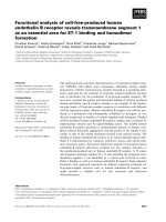
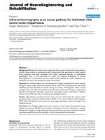
Eqs. (6) and (7), it is clear that the efficiency enhancement (EE) defined as Ee f f = 10 × log (η)
depends on the nonlinear coefficient of refractive index and laser intensity. This conclusion is
proved in Fig. 3 plotted with given parameters: ns f = 1.45, n p = 1.5, i.e., m > 1 (a) and n p = 1.3,
i.e., m < 1 (b). We can see that in the case m > 1 (Fig. 3a), the EE increases with increasing
of both facts, laser peak intensity and nonlinearity of particle, but it has an asymptote value of
16.42 dB. This value is corresponding to the maximum value of ratio m2nl − 1 m2nl + 2 = 1.
202
NONLINEAR OPTICAL TWEEZERS AS AN OPTICAL METHOD FOR CONTROLLING PARTICLES . . .
For the m < 1 (Fig. 3b), the EE-peak intensity characteristics are plotted forpurpose to compare
with the case of m = n p /ns f = 1.5/1.45 > 1. We can see that the optical trap is not efficient till
n p + n2 I = ns f and then the EE increases with an increasing peak intensity and nonlinearity of
particle. Consequently, the OTE is remarkably enhanced for the Kerr particle, even for the particle
with m < 1 by tweezers using pulsed Gaussian beam with high intensity [21, 22]. That means, it is
not necessary to use Hollow-Gaussian beam to trap Kerr particle with m < 1 till the laser intensity
satisfying the condition I0 ≥ (ns f − n p ) /n2 [15].
(a)
(b)
Fig. 3. Eeff vs. I0 with different n2 . a): m > 1 and b): m < 1.
IV. NOT USING KERR EMBEDDING FLUID
Now, we consider a linear particle with n p = 1.5 embedded in the thin nonlinear surrounding fluid with refractive index of 1.45 + n2 I [15]. In this case, the index ratio is modified as:
np
mnl (ρ, z) =
(8)
ns f + n2 I(ρ, z)
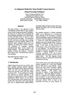
Using Eqs. (7) and (8), the EE-peak intensity characteristics are numerically calculated and
presented in Fig. 4. Form Fig. 4a, we can see that the EE reduces with increasing of peak intensity
and nonlinearity of surrounding fluid. That means, in the surrounding fluid with low nonlinearity,
the Kerr effect can be neglected. The Kerr effect can be neglected also if the nonlinearity of
particle is larger than that of surrounding fluid, since in this case the EE still rises up (Fig. 4b). It
is clear that using Kerr surrounding fluid in OT can reduce the OTE of OT using Gaussian beam.
However, a Kerr surrounding fluid having thickness many times larger than the particle size in
OT can play an important role of the optical method to control the particle in space [6, 36]. As
we know, a nonlinear medium irradiated by the intense laser Gaussian beam can be the nonlinear
lens [37]. Consequently, the laser beam will be reshaped by the nonlinear lens as shown in Fig. 5.
Consider an input Gaussian beam with intensity distribution given in Eq. (1) that irradiates the
HO QUANG QUY
203
(a)
(b)
Fig. 4. (a) Eeff vs. I0 with different n2 of surrounding fluid; (b) Eeff vs. I0 with different
n2p of particle and fixed n2s f of surrounding fluid.
Kerr medium with thickness of d (Fig. 5). Using the propagation matrix [37] of light through
optical system consisting of m thin plates with thickness ∆z = d/m and Kerr relation in Eq. (8),
the intensity redistribution of laser beam propagating through the ith plate is derived as follows
1
Im,i (ρ, z) = I0 ×
1+
z+(zi +∆z)
z0,i
ρ2
×
exp
− 2
2
W0,i
1
(9)
z0,i = Mi2 z0,(i−1)
(10)
1+
z+(zi +∆z)
z0,i
2
where
W0,i = MiW0,(i−1) ,
zi = Mi2 (∆z − fnl,i ) + fnl,i ,
are the radius of beam waist, waist position and Rayleigh distance, respectively. Mi = Mr,i /
ri = z(i−1) /(∆z − fnl,(i−1) ), Mr,i = | fnl,i /∆z − fnl,i |, and
1 + (∆z/z0,(i−1) )2
fnl,i =
2nnl I0 ∆z
1 + ri2 ,
2
(11)
is the focal length of ith nonlinear lens.
We have observed the reshaping of an input Gaussian beam with wavelength of λ = 1.06 µm,
peak intensity of I0 = 3.5 × 10⁸ W/cm2 and beam waist of W0 = 2 µm located at distance d =
−10 µm from input surface of Kerr medium. Its intensity distribution in phase plane (ρ, z) is
illustrated in Fig. 6a. Using Eqs. (9) – (11), the intensity distributions of modified Gaussian beam
through Kerr medium with ns f = 1.45, n2s f = 1 × 10⁻¹⁰ cm2 /W and n2s f = 2 × 10⁻¹⁰ cm2 /W
are cascade simulated and shown in Fig. 6b and Fig. 6c, respectively. We can see that when the
nonlinearity of Kerr medium increases, the radius of beam waist reduces from 2 through 1.8 to
204
NONLINEAR OPTICAL TWEEZERS AS AN OPTICAL METHOD FOR CONTROLLING PARTICLES . . .
Fig. 5. Sketch of NOT with thick Kerr medium using Gaussian beam [36].
1.4 µm, while its position moves close to the input surface of Kerr medium from 10 through 6.82
to 3.82 µm. Substituting Eq. (9) to Eq. (2) we have the axial gradient force as follows [14]:
Fgrd,z (ρ, z) = −ˆz
2βn,i (ρ, z)Im,i (ρ, z)
nm,i (ρ, z)ε0 ckW0,i
1
1+
z+(zi +∆z)
z0,i
2
2
×
z + (zi + ∆z)
z20,i
(12)
where βn,i (ρ, z) is the polarity and nm,i (ρ, z) is the total index of Kerr medium relating to Im,i (ρ, z).
The distribution of axial gradient force acting on the dielectric particle (a = 200 nm, n p =
1.5) is changed, with different value of nonlinearity of Kerr medium. The distributions of Fgrd,z (ρ, z)
for n2s f = 0, n2s f = 1×10⁻¹⁰ cm2 /W, n2s f = 2×10⁻¹⁰ cm2 /W are presented in Fig. 6d, Fig. 6e and
Fig. 6f, respectively. We can see that the trap site, where Fgrd,z (ρ, z) = 0, moves close to the input
surface with increasing of nonlinearity of medium. The dependence of the trap site, where particle
is stably trapped in Kerr medium on the laser intensity, gives us an idea to tune laser intensity for
controlling trapped particle in the space. A NOT using two laser sources used to control trapped
bead linked to ADN molecule is investigated [6]. In the configuration presented in Fig. 7a, a weak
laser is used to control the radial position (stable position, ρst ) of trapped linked to DNA molecule
(Fig. 7b), and an intense one is used to control the axial position (stable position, zst ). The motion
of trapped bead linked to DNA molecule in Kerr medium, under optical forces and elastic force
can be theoretically observed by using the general Langevin equation [38]:
¨ = −γ ρ(t)
˙ + Fgrd,ρ (ρ(t)) − Fel (ρ(t)) +
mρ(t)
2kB T γWρ (t)
(13)
where m is the bead mass; γ = 6πηa is the friction coefficient;η is the viscosity of surrounding
fluid, a is the radius of bead, kB is Boltzmann constant, T is the temperature, Wρ (t) is the white
noise, ρ is the bead’s radial position (Fig. 7b), the last three terms in the right are the radial optical
gradient, elastic and Brownian forces, respectively. The elastic force of DNA molecule is given as
follows [39, 40]:
kB T ρ − ρ0
1
1
Fel (ρ) =
+
−
(14)
2
Lb
L
4
4 (1 − (ρ− ρ0 ) /L)
HO QUANG QUY
205
(a)
(b)
(c)
(d)
(e)
(f)
Fig. 6. Intensity (a), (b), (c) and axial gradient force (d), (e), (f) distributions in phase
plane (ρ, z) of Kerr medium.
where Lb , L are the persistence and contour lengths of DNA molecule, respectively, ρ0 is the begin
position of trapped bead (and of anchor’s position). Using the experimental parameters as given
in Ref. [6], the radial position (Fig. 7c) and axial position-average power characteristics (Fig. 7d)
are numerically plotted for polystyrene bead [38] linked to λ -phage DNA molecule [39].
Under the action of the radial optical force the trapped bead speedily moves close to laser
axis, and it reaches to the stable site till the optical force and the elastic force of DNA molecule
are in balance. Based on this phenomenon, the stable position of trapped bead in radial direction
can be controlled by tune of weak laser power (Fig. 7c). This investigated controlling method
is absolutely similar to using a convenient OT using the linear surrounding fluid [1]. In some
cases for that the contour length of DNA molecule is too long, meanwhile the begin position of
trapped bead is close to the laser axis, the stretched length does not reach to the extreme by this
method [40]. Though the trapped bead can be held in the stable position, the stretched length of
DNA has not reached to the extreme. It is necessary to move this site along the laser axis. For
this purpose, the efficient way is to use the intense laser. As shown in Fig. 5, by tune of intense
laser power, the stable position moves in axial direction (Fig. 7d). From Fig. 7d, if the power of
intense laser changes an interval of 2.5 kW, the stable position can change an interval of 40 µm,
206
NONLINEAR OPTICAL TWEEZERS AS AN OPTICAL METHOD FOR CONTROLLING PARTICLES . . .
Fig. 7. Sketch of NOT using two lasers; b) DNA with two bead in Kerr medium; c)
Radial position vs. weak laser power [6]; d) Axial position vs. intense laser power [6].
so the proposal NOT can longitudinally control any DNA molecules with contour length shorter
than 40 µm linked to trapped bead located on the axis of intense laser.
V. OT USING THIN LAYER OF ORGANIC DYE (NOTOD)
As shown above, the NOT using Kerr medium (Fig. 7a) can be used as an all-optical method
to control particle in 3D space. However there are two weak points: the first one is the necessity
of high laser intensity, which can biophysically damage the trapped bead, and the second one
belongs to biochemical properties, the Kerr medium is not always suitable to different kinds of
trapped bead and DNA molecule. To pass those complexities, a NOTOD using Kerr medium
with the high nonlinearity as added nonlinear lens has been proposed [29, 30]. The configuration
of NOTOD using the organic dye Acid Blueis presented in Fig. 8a. The difference between
the conventional OT and NOTOD is that the high NA microscope objective is replaced by an
HO QUANG QUY
207
optical system consisting of a low NA objective and thin layer of Acid Blue. Acid blue is an
organic dye which has nonlinearity of n2 ∼ 1×10⁻⁶ cm2 /W, which is much higher than convenient
liquids [41]. Irradiated by the intense Gaussian beam (as Eq. (1)), the layer of Acid blue can be a
nonlinear lens with the nonlinear focal length given by [29]:
fnl =
W02
dn2 I0
(15)
where d is the thickness of layer.
(a)
(b)
Fig. 8. a) Sketch of NOTOD using thin layer of Acid Blue; b) Focal length of thin layer
with different thickness vs. average power of incoming Gaussian laser beam, and W0 =
0.002 cm.
Consider a plate CW beam focused by a low NA objective to Gaussian beam with waist of
W0 = 0.002 cm which is about 20 times larger than the laser spot which is for conventional TO
(about 2 µm) irradiating a thin layer of Acid blue. Because of high intensity of incoming Gaussian
beam, the thin layer of Acid Blue becomes nonlinear lens, which has focal length fnl depending on
an average power of laser and thickness of Acid blue layer (Fig. 8b). It is clear that the nonlinear
focal length is shorter when the laser power is higher and the layer is thicker. It not only becomes
the nonlinear lens, but also in return reshapes the incoming laser beam whose intensity distribution
on plane (ρ, z) is given as follows [29]:
I0
I(ρ, z) =
1+
zπ(dn2 I0 )2
λW02
−
exp
2
ρ2
λW0
πdn2 I0
2
1+
zπ(dn2 I0 )2
λW02
2
(16)
Using Eq. (16) and choosing d = 0.05 cm, the intensity distribution of reshaped laser beam
in phase plane(d = −2W0 ÷ 2W0 , z = − fnl ÷ fnl ), where W0 = λW0 /πdn2 I0 is the waist’s radius,
is numerically observed with different average power of incoming beam and presented in Fig. 9.
208
NONLINEAR OPTICAL TWEEZERS AS AN OPTICAL METHOD FOR CONTROLLING PARTICLES . . .
Fig. 9. Distribution of intensity of reshaped laser beam in phase plane (ρ, z) with different
average power of incoming laser [31].
We can see that the radius of reshaped laser beam W0 and the focal length of nonlinear lens fnl are
decreased when the average power of incoming laser beam P = πW02 I0 /2 increases, consequently,
intensity is more and more enhanced around the focus. The important point here is that the intensity gradient enhances with increasing of average power. Using Eqs. (2), (4) and (16), the total
axial force acting on the dielectric particles is given as follows:
Ftotal,z (ρ, z)
=ˆz −2πn f l a3
+
128π 5 a3
3λ 4
2
nb
nfl
−1
2
+2
nb
nfl
nb
nfl
nb
nfl
2z
π(dn2 I0 )2
λW02
1+
2
−1
× I0 exp
2
−
+2
zπ(dn2 I0 )2
λW02
2
2
ρ2
λW0
πdn2 I0
2
1+
2
zπ(dn2 I0 )
λW02
2
− 1
2
ρ2
λW0
πdn2 I0
2
1+
zπ(dn2 I0 )2
λW02
2
.
(17)
Using parameters given above to Eq. (17), the distribution of total axial force along laser
beam axis is numerically plotted in Fig. 10. From this figure we can see: first, when the average
HO QUANG QUY
209
power is tuned an amount of ∆P = 3 mW, the trap center will move a distance of ∆ztc = 0.38 cm;
second, with an increasing of the average power the distance between two peaks which is called
trap region, ∆zst [34] reduces and the peak force increases. The second point shows that the OTE
increases. The enhancement of OTE of NOTOD in comparison to that of linear optical tweezers
(LOT) using Gaussian beam with average power of P = 1 mW, and W0 = 2 µm is observed in
peak
peak
c/ns f P.
c/ns f P and Qz,max = Fgrd,z
Fig. 10. The curves in Fig. 11 are plotted for Qρ,max = Fgrd,ρ
Fig. 10. Distribution of longitudinal force along laser beam axis [28].
We can see that OTE of LOT depends not on the laser power, but it is opposite to NOTOD. If
P ≤ 2.15 mW the OTE of NOTOD is smaller than that of LOT, but it is opposite if P ≥ 2.15 mW.
This property can be explained as that the nonlinear effect appears not in layer of Acid Blue,
means the nonlinear lens appears not until the average laser power is higher than certain threshold.
Consequently, the NA of optical system is smaller than that of microscope objective used in LOT.
And then, the average power increases larger than threshold that leads the beam waist as well as
Rayleigh distance reduces, consequences increasing of intensity gradient of laser beam. It results
in the increase of the optical forces and then enhancement of OTE of NOTOD, meanwhile, OTE
210
NONLINEAR OPTICAL TWEEZERS AS AN OPTICAL METHOD FOR CONTROLLING PARTICLES . . .
of LOT is constant, as seen from Eqs. (1), (3) and (5): the OTE of LOT can be derived as
2
1
α
I0 exp −
2
2
1+(z/z
(
z
peak
0) )
W0 1+ z
cFgrd,ρ
c
0
Qρ,max =
=
πW02 I0
ns f P
ns f
2
1
4cα
= const
exp −
=
2
2
z
3
1
+
(z/z
)
0
πns f W0 1 + z0
(18)
peak
is fitted at ρ = W0 . That is similar for Qz,max , which is independent from the average
here Fgrd,ρ
laser power.
(a)
(b)
Fig. 11. |Qρ,max | (a) and |Qz,max | (b) vs. P.
HO QUANG QUY
211
VI. FLEXIBILITY OF CHOOSING NOTOD FOR DNA MOLECULES
(a)
(b)
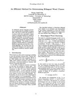
Fig. 12. (Color online) Bead position-pulling time characteristics of polystyrene bead
linked to λ -phage DNA with peak intensities (down-up) of I0 = 0.995 × 10⁵ Wcm−2
(magenta), I0 = 0.99 × 10⁵ Wcm−2 (blue), I0 = 0.985 × 10⁵ Wcm−2 (green), I0 = 0.98 ×
105 Wcm−2 (black). b) Bead position-pulling time characteristics of polystyrene bead
linked to BEC with peak intensities (down-up) of I0 = 0.98 × 10⁵ Wcm−2 (magenta),
I0 = 0.96 × 10⁵ Wcm−2 (blue), I0 = 0.94 × 10⁵ Wcm−2 (green), I0 = 0.93 × 10⁵ Wcm−2
(black).
The main purpose of using OT in biophysics is to stretch DNA molecule in the extreme
stretched state in which stretched length is comparable to contour length. As we know, the different kind of DNA has own contour length, may be from some nanometers (plasmid DNA with
212
NONLINEAR OPTICAL TWEEZERS AS AN OPTICAL METHOD FOR CONTROLLING PARTICLES . . .
contour length of 3 nm [42]) to some millimeters (Bacteria Escherichia Coli (BEC) with contour
length of 1.5 mm [43]). It is very difficult to use a linear OT to stretch all of DNA kind by electrooptical or electro-mechanical methods [1, 9–13]. But the difficulty can be overcome when using
NOTOD. As shown in Sec. 5, the stable site of trapped bead can be controlled with high OTE by
tune of laser power. It is favorable to use NOTOD for stretching of DNA molecules. By MATLAB software using finite element method [6, 38, 40], the general Langevin equation as shown
in Eq. (13) is solved, consequently, we observed numerically the position-pulling time characteristics of polystyrene bead (a = 200 nm, n p = 1.5) linked to λ -phage λ I0 = 0.995 × 10⁵ Wcm−2 ,
I0 = 0.99×10⁵ Wcm−2 , I0 = 0.98×10⁵ Wcm−2 , I0 = 0.98×10⁵ Wcm−2 , I0 = 0.96×10⁵ Wcm−2 ,
I0 = 0.94 × 10⁵ Wcm−2 DNA with different peak intensities of laser beam with W0 = 0.01 cm.
From Fig. 12a, we can see that if the intensity is chosen of I0 = 1 × 10⁵ Wcm−2 and the longitudinal force hold trapped bead at beginning position of 1000 µm from the output surface of Acid blue
layer, then, by lowering the intensity, the trapped bead moves far away from the output surface of
Acid blue layer. The main result is that when intensity is tuned an amount of 2 kW/cm2 (black
curve), the trapped moves a distance about of 16.5 µm, which is comparable to the contour length
of λ -phage DNA molecule [42]. This situation is similar to the case of BEC in Fig. 12b. By
slightly changing NA of low NA microscope objective, so that the beam waist is W0 = 0.045 cm.
With fixed beginning intensity I0 = 1 × 10⁵ Wcm−2 the bead hold at the longitudinal position
of 20.25 mm from output surface of Acid blue layer, and then by tuning intensity lower to pull
trapped bead farther. When intensity is tuned lower an amount of 7 kW/cm2 the motion distance
of trapped bead linked to BEC is about 1.4 mm comparable to the contour length. The aboveobtained results show that by finely tuning intensity of laser, the NOTOD can be used to stretch
DNA molecule with the different contour length limited in certain long interval. That shows the
flexibility of NOTOD.
VII. CONCLUSION
The influence of Kerr effect on the properties of optical tweezers is resumed. The optical
trap efficiency is higher for Kerr particle, since the index ratio (m) is enhanced, i.e. particle’s
refractive index is raised up by laser intensity. Even though particles have refractive index smaller
than that of linear surrounding fluid, it is not necessary to use the hollow beam. The optical
tweezers using Kerr medium (NOT) will be a tool to control linear particle in space by tuning
laser power, which called the all-optical method although it can reduce optical trap efficiency,
since the index radio is reduced by the laser intensity. The weakness of optical tweezers using Kerr
medium is overcome by NOTOD, which uses organic dye as nonlinear lens replacing the nonlinear
surrounding fluid. The proposed NOTOD is not only compact, having high optical efficiency, but
also a flexible tool for optical method to control trapped bead in space and to stretch different
kind of DNA molecules. Using organic dye with high nonlinearity, the optical trap efficiency of
NOTOD is high enough, which can trap nanoparticle [21, 22] and stretch DNA molecule [44–47],
instead of using ultrafast pulsed laser.
The organic dye is not only in liquid phase, but also can be prepared as thin layer. Moreover, its linear index [28] is comparable to that of immersion oil, which is used to enhance NA
of microscope objective [48]. So thin layer of organic dye could be used as immersion oil to
design nonlinear immersion microscope objective for OT. We hope our suggestions may become
advantageous in the going time.
HO QUANG QUY
213
ACKNOWLEDGMENT
This research is funded by Vietnam National Foundation for Science and Technology Development (NAFOSTED) under grant number 103.03-2018.342.
REFERENCES
[1] J. H. G. Huisstede, Scanning probe optical tweezers: A new tool to study dna-protein interactions, Ph.D. thesis,
University of Twente, 2006.
[2] P. Jing, J. Wu, G. W. Liu, E. G. Keeler, S. H. Pun and L. Y. Lin, Scientific reports 6 (2016) 19924.
[3] A. Ashkin, Physical review letters 24 (1970) 156.
[4] M. P. MacDonald, L. Paterson, W. Sibbett, K. Dholakia and P. E. Bryant, Optics Letters 26 (2001) 863.
[5] D. Min, M. A. Arbing, R. E. Jefferson and J. U. Bowie, Protein Science 25 (2016) 1535.
[6] T. T. Dinh, K. D. Quoc, K. B. Xuan and Q. H. Quang, Optical and Quantum Electronics 48 (2016) 561.
[7] M. F. Duarte, M. A. Davenport, D. Takhar, J. N. Laska, T. Sun, K. F. Kelly and R. G. Baraniuk, IEEE signal
processing magazine 25 (2008) 83.
[8] K. C. Neuman and S. M. Block, Review of scientific instruments 75 (2004) 2787.
[9] G. R¨omer and P. Bechtold, Physics procedia 56 (2014) 29.
[10] E. R. Dufresne, G. C. Spalding, M. T. Dearing, S. A. Sheets and D. G. Grier, Review of Scientific Instruments 72
(2001) 1810.
[11] Y. Tanaka, H. Kawada, S. Tsutsui, M. Ishikawa and H. Kitajima, Optics express 17 (2009) 24102.
[12] D. Min, M. A. Arbing, R. E. Jefferson and J. U. Bowie, Protein Science 25 (2016) 1535.
[13] Y. Hao, C. Canavan, S. S. Taylor and R. A. Maillard, Scientific reports 7 (2017) 10843.
[14] H. Van Nam, C. T. Le and H. Q. Quy, Comm. Phys. 23 (2013) 155.
[15] Q. Q. Ho et al., J. Phys. Scien. and Appl. 2 (2012) 301.
[16] H. Okamoto, Y. Jiang and T. Narushuima, Progress in electromagnetic research symposium, PIERS, 2016.
[17] T. T. Doan, K. D. Quoc and Q. H. Quang, Optical and Quantum Electronics 50 (2018) 51.
[18] M. Weber, Crc handbook of optical materials, 2003.
[19] M. Jahja, On nonlinear optical constants of polystyrene, International Symposium on Modern Optics and Its
Applications, 2011.
[20] K. Tanaka, Journal of Materials Science: Materials in Electronics (2005) 633.
[21] A. Devi and A. K. De, Optics Express 24 (2016) 21485.
[22] Y. Jiang, T. Narushima and H. Okamoto, Nature Physics 6 (2010) 1005.
[23] Q. Wu, S. Chang and X. Huang, Flexible and highly effective trapping particles of optical tweezers in nonlinear
optical imaging, Frontiers in Optics, Optical Society of America, 2018, pp. JW3A–119.
[24] H. Q. Quy and T. B. Tru, Comm. Phys. 6 (1996) 23.
[25] E. Koushki, A. Farzaneh and S. Mousavi, Applied Physics B 99 (2010) 565.
[26] R. R. Krishnamurthy and R. Alkondan, Optica Applicata 40 (2010) 187.
[27] S. Jeyaram and T. Geethakrishnan, Optics & Laser Technology 89 (2017) 179.
[28] L. T. Nguyen, N. T. Hong, C. T. B. Thi and A. Q. Le, Journal of Nonlinear Optical Physics & Materials 23 (2014)
1450020.
[29] Q. H. Quang, T. T. Doan, T. D. Quoc and T. N. Manh, Optics Communications 421 (2018) 94.
[30] H. Q. Quy, D. Q. Tuan, T. D. Thanh and N. M. Thang, Optics Communications 427 (2018) 341.
[31] D. Q. Tuan, N. T. T. Tam, H. T. Loan and N. T. Cam, Journal of Military Science and Technology: Special Issue
57A (2018) 97.
[32] J. Du, C.-H. Yuen, X. Li, K. Ding, G. Du, Z. Lin, C. Chan and J. Ng, Scientific reports 7 (2017) 18042.
[33] T. Godazgar, R. Shokri and S. N. S. Reihani, Optics letters 36 (2011) 3284.
[34] H. Q. Quy, M. Van Luu, H. D. Hai and D. Zhuang, Chinese Optics Letters 8 (2010) 332.
[35] A. Ashkin, Biophysical journal 61 (1992) 569.
[36] V. Hoang, T. Cao and Q. Ho, Int. J. Eng. Innov. Techno. 3 (2013) 134.
[37] B. Saleh and M. Teich, Fundamentals of photonics [electronic resource], Wiley, 1991.
[38] G. Volpe and G. Volpe, American Journal of Physics 81 (2013) 224.
214
NONLINEAR OPTICAL TWEEZERS AS AN OPTICAL METHOD FOR CONTROLLING PARTICLES . . .
[39] P. Mangeol, D. Cˆote, T. Bizebard, O. Legrand and U. Bockelmann, Eur. Phys. J. E 19 (2006) 311.
[40] T. D. Trung, Control the tension of dna molecule in nonlinear solvent with optical tweezers, Ph.D. thesis, Vinh
University, 2017.
[41] E. Koushki, A. Farzaneh and S. Mousavi, Applied Physics B 99 (2010) 565.
[42] D. T. Thai, V. L. Chu and Q. Q. Ho, IJEIT 3 (2014) 159.
[43] C. G. Baumann, V. A. Bloomfield, S. B. Smith, C. Bustamante, M. D. Wang and S. M. Block, Biophysical journal
78 (2000) 1965.
[44] S. Bakshi, A. Siryaporn, M. Goulian and J. C. Weisshaar, Molecular microbiology 85 (2012) 21.
[45] A. Keloth, O. Anderson, D. Risbridger and L. Paterson, Micromachines 9 (2018) 434.
[46] F. Falleroni, V. Torre and D. Cojoc, Frontiers in cellular neuroscience 12 (2018) 130.
[47] J. Liu and Z. Li, Micromachines 9 (2018) 232.
[48] A. A. R. Neves, A. Fontes, C. L. Cesar, A. Camposeo, R. Cingolani and D. Pisignano, Physical review E 76 (2007)
061917.