The phenomenon of evaporative cooling from a humid surface as an alternative method for air-conditioning
Bạn đang xem bản rút gọn của tài liệu. Xem và tải ngay bản đầy đủ của tài liệu tại đây (857.58 KB, 28 trang )
I
NTERNATIONAL
J
OURNAL OF
E
NERGY AND
E
NVIRONMENT
Volume 1, Issue 1, 2010 pp.69-96
Journal homepage: www.IJEE.IEEFoundation.org
ISSN 2076-2895 (Print), ISSN 2076-2909 (Online) ©2010 International Energy & Environment Foundation. All rights reserved.
The phenomenon of evaporative cooling from a humid
surface as an alternative method for air-conditioning
E. Velasco Gómez, F.C. Rey Martínez, A. Tejero González
Thermal Engineering Group, Department of Energy Engineering and Fluid mechanics, School of
Engineering, University of Valladolid, Paseo del Cauce nº 59, 47011 Valladolid, Spain.
Abstract
The phenomenon of evaporative cooling is a common process in nature, whose applications for cooling
air are being used since the ancient years. In fact, it meets this objective with a low energy consumption,
being compared to the primary energy consumption of other alternatives for cooling, as it is simply based
in the phenomenon of reducing the air temperature by evaporating water on it. This process can be an
interesting alternative to conventional systems in these applications where no very low temperatures are
needed, like the case of air-conditioning during the summer. However, the risk of contamination by
legionnaire’s disease, commonly related to evaporative cooling systems, has led in recent years to the
substitution of these devices in the industry by less-efficient systems, like the case of cooling towers or
evaporative condensers substituted by air-condensing refrigerating processes.
Therefore, these systems based in the evaporative cooling are rarely used for cooling buildings. To
reduce this risk, evaporative cooling is produced from humid surfaces, in such a way that water
evaporates due to the difference of vapor pressure between the surface and the air, and thus minimizing
the generation of aerosols, responsible for the spread of legionnaire disease. Aerosols are nevertheless
produced in conventional systems where water is sprayed or directly in contact with the stream of air;
and the problem worsens if the water, which is recirculated, has been still in any moment or its
temperature is adequate for the bacteria proliferation.
This paper aims to introduce the thermodynamic basis in which the process is based, as well as the
commercial evaporative systems and the problem associated to legionnaire’s disease in this kind of
systems. Furthermore, three different experimental devices based in evaporative cooling are described,
which have been designed and manufactured in the Thermal Engineering Research Group of the
University of Valladolid., describing their characteristics of operation and providing the experimental
results obtained during their characterization, for outside air conditions typical of hot and dry summers.
Copyright © 2010 International Energy and Environment Foundation - All rights reserved.
Keywords: Direct evaporative cooling, Air-conditioning, Energy efficiency, Legionnaire’s disease.
1. Introduction
The environmental impact associated to the use of energy from conventional fossil origin, the energetic
and economic dependency on non-renewable sources, lead to the necessity of reducing the energy
consumption, maintaining the current targets and necessities of each activity that require the use of
energy.
International Journal of Energy and Environment (IJEE), Volume 1, Issue 1, 2010, pp.69-96
ISSN 2076-2895 (Print), ISSN 2076-2909 (Online) ©2010 International Energy & Environment Foundation. All rights reserved.
70
Figures about the energy consumption by fields show that from 20% to 40% of the total energy demand
in developing countries is generated in buildings, depending on the climatic conditions [1]. Moreover,
due to the high number of users of the building sector, an improvement on the energy efficiency of the
systems leads to an important decrement on the energy consumption, thus being this sector one of the
most interesting fields to focus the activity to improve the energy efficiency. However, not only the
economic savings have to be considered in the study of the improvements in energy efficiency, whose
profitability is commonly uncertain, but also the reduction in the environmental impact or in the misused
of natural resources implied [2].
Despite the fact that the priority of the new dispositions introduced for energy management, new devices
and generators among others, is to reduce the energy consumption in buildings, they must ensure a
proper comfort level and well being of their users [3]. Consequently, it should be considered the
introduction of systems that permit condition the hygrothermal environment of the rooms, maintaining an
adequate indoor air quality and thermal comfort, with low energy requirements, when providing
energetic viable solutions to obtain a proper thermal environment in buildings.
There are many sustainable alternatives in the air-conditioning of buildings, which consist in minimizing
the energy demand by improving the thermal insulation, taking advantage of the bioclimatic facilities, or
using energy resources different from the conventional ones, like solar energy generation, geothermic
heat pumps, or evaporative cooling systems, which are the ones studied in this work.
This paper introduces the characteristics as well as some of the experimental results obtained for
different prototypes based in the phenomenon of evaporative cooling, and that have been developed in
the Thermal Engineering Research Group of the University of Valladolid.
2. History of evaporative cooling
Many examples of the application of the phenomenon of evaporative cooling can be found, such as the
metabolic regulation of the human body temperature through the evaporation of sweat from the skin, the
use of cooling towers or evaporative condensers, the cooling of pools by the evaporation of the water,
etc. Furthermore, it was the most widespread method to cool the environment in ancient years, before
developing the principles of refrigeration by mechanical compression or absorption. It is important to
note which are the historical background and the development of this technology till nowadays.
Originally, this process was firstly applied by humankind in Near East, where the dry and hot climate
was favorable to its application. Thus, in paintings from Ancient Egypt (2500 B.C.) it can be seen how
slaves fanned big vessels filled with water, which were porous enough to permit this water to pass
through the ceramic wall and maintain the surface humid, evaporating into the air [4].
Other paintings from Rome, founded in a wall from Herculano (70 A.D.), show a big Wessel made of
leather used to cool the drinking water making use of this process. Similarly, the Persian and American
Indians tents were maintained humid to be cooled. Other similar applications of the evaporative cooling
are used nowadays, like the water bottles of the soldiers covered with wet cloth; or the drinking jugs,
which provide drinking water at a temperature below that of the environment.
Moreover, old buildings from Iran were commonly cooled by this process, as they were partially built
underground to avoid solar radiation, while the upper terraces were provided with pools of water cooled
in a kind of cooling towers.
During Middle Age, the Islam spreads this technology all throughout the Occidental countries, and
evaporative cooling systems start being used in Mediterranean areas. Leonardo da Vinci probably built
the first mechanical air-cooler made of a hollow wheel through which the air was conducted, keeping in
contact with a water curtain that fell into different chambers, cooling and purifying the air. The system
included wood valves to control it, and it was designed to cool the rooms of his boss’ wife [5].
The first rigorous analysis of the direct and indirect evaporative systems, considering both the advantages
and disadvantages and indicating and establishing some basis about their design, was developed by Dr.
John R. Watt, who worked for the Research Laboratory of the U.S. Navy. He built and studied four
prototypes of plate evaporative coolers, one of them constituted of two stages; as well as a cooling tower
and coil, determining their efficiency and cooling capacity [6].
Currently, the work developed by Dr. Donald Pescod gathers different studies about plate evaporative
coolers, being the pioneers in using plastic materials for the plates, and in creating artificial turbulences
to minimize the stillness of the air film, reaching really high heat-transfer areas in compact distributions
[7]. As the main resistance to heat-transfer can be found in the air on the dry face of the system, the
advantage of the higher thermal conductance of metals than that of plastics is negligible. Moreover,
International Journal of Energy and Environment (IJEE), Volume 1, Issue 1, 2010, pp.69-96
ISSN 2076-2895 (Print), ISSN 2076-2909 (Online) ©2010 International Energy & Environment Foundation. All rights reserved.
71
plastic avoids corrosion and is adequate to resist the high pressure differences characteristic of this kind
of devices.
In the 80’s, the interest in these systems increases considerable, as probes the high number of articles and
communications in scientific journals, developing different applications of this technology like the
recovering of the energy associated to the return air stream from the cooled rooms.
3. Theory on evaporative cooling
Evaporative cooling is a process of heat and mass transfer based on the transformation of sensible heat
into latent heat. The non-saturated air reduces its temperature, providing the sensible heat that transforms
into latent heat to evaporate the water. If the process develops in ideal adiabatic conditions, the dry bulb
air temperature decreases as this transformation develops, increasing its humidity. This heat exchange
continues until the air reaches its saturated state, when the air and water temperature reach the same
value, called “adiabatic saturation temperature”, being the process known as “adiabatic saturation”.
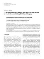
To define this temperature we can suppose a long adiabatic tunnel, in which the humid air is introduced
in certain conditions, while water is sprayed inside the tunnel and then recirculated, in such a way that
the air becomes saturated (see Figure 1).
The adiabatic saturation temperature, Tad sat, is the temperature that the air reaches when gets to the
output of the tunnel, if water is provided and evaporated at that temperature.
Figure 1. Adiabatic saturation tunnel
In the last stages of the tunnel there will be no mass-exchange because Relative air Humidity (RH) is
100%, and heat exchange neither, as the air and water temperature are the same. Thus, these conditions
only depend on those of the inlet air and, consequently, the saturation air temperature can be defined as a
thermodynamic property of humid air.
The value of the wet bulb temperature is close to that of the saturated air temperature in the common
working conditions of air-conditioning systems. However, they are completely different concepts, as the
first one is conceived as the temperature that reaches the bulb of a thermometer when the heat transferred
from air, essentially by convection processes, is the same as the heat required to evaporate the water from
its surface into the air, due to the vapor pressure gradient between the bulb’s surface and the air.
Figure 2 shows the heat and mass flows involved in the process introduced to define the wet bulb
temperature.
Heat transferred from air to the bulb by convection:
()
wb
TThq −=
∞
(1)
where q is the heat flux (W/m
2
), h is the convective heat coefficient (W/m
2
C), T
∞
is the air temperature
(C) and T
wb
is the wet bulb temperature (C).
Water suppy at T
ad sat
Non-saturated air
T
1
RH
1/
h
1
h
ad sat =
h
1
T
ad sat
RH = 100 %
Saturated state
Isolation
Isolation
International Journal of Energy and Environment (IJEE), Volume 1, Issue 1, 2010, pp.69-96
ISSN 2076-2895 (Print), ISSN 2076-2909 (Online) ©2010 International Energy & Environment Foundation. All rights reserved.
72
Figure 2. Wet bulb temperature (T
wb
)
Vapour flow from the bulb to the air:
()
∞
•
−= XXhm
wb
T
satdam
/
··
ρ
(2)
where
m
&
is the mass flow (kg/m
2
), h
m
is the convective mass coefficient (kg/m
2
s), ρ
da
is the dry air
density (kg
as
/m
3
), which is the inverse value of the specific volume, X
∞
is the air absolute humidity
(kg/kg
da
) and X
sat/Twb
is the absolute humidity at saturation point of these conditions of wet bulb
temperature (kg/kg
da
).
Heat flow required to evaporate the water from the bulb’s surface into the air:
()
∞
−⋅= XXhq
Twbsatdam /
ρλ
(3)
where λ is the latent heat associated to the phase change (J/kg).
The equations introduced could be more complicated if other kind of exchanges with the environment
were considered. The advantage of using the wet bulb instead of the adiabatic saturation temperature is
that, although they correspond to different concepts, their value is quite similar and the first one is easier
to measure, as only a thermometer whose bulb is maintained humid is required.
It can be demonstrated from the Lewis number (eq. 4) that, for a mixture of dry air and water vapour, the
outlet air temperature in an adiabatic saturation tunnel, thus the adiabatic saturation temperature, is
mainly the same as the wet bulb air temperature. However, slight differences can be appreciated between
both values of temperature.
mp
hC
h
D
Le
⋅⋅
==
ρ
α
(4)
where α is the thermal diffusivity (m
2
/s), D is the mass diffusivity (m
2
/s), Cp is the specific heat (J/kgC)
ρ is the density (kg/m
3
).
The process of adiabatic saturation controls most of the evaporative cooling systems. This is the basic
process in those cases in which the water initial temperature is close to the wet bulb temperature of inlet
air, which usually occurs when water is recirculated continuously. Theoretically, water temperature
T
wb
X
sat/Twb
T
wb
T
∞
X
∞
q
m
&
International Journal of Energy and Environment (IJEE), Volume 1, Issue 1, 2010, pp.69-96
ISSN 2076-2895 (Print), ISSN 2076-2909 (Online) ©2010 International Energy & Environment Foundation. All rights reserved.
73
kg/kg
da
%
C
Line of constant enthalpy
Adiabatic saturation
temperature
≈ Wet bulb air temperature
A
B
maintains constant, and consequently all the heat involved in the evaporation process is used to cool the
air, not the water.
Nevertheless, in practice water usually gains some external sensible loads in the tank, pumps and pipes.
Moreover, the temperature of the water supplied to support the evaporated part and purges, is not
necessarily the adiabatic saturation temperature of inlet air. Thus, in an evaporative cooling process the
concept of “adiabatic saturation” is only the theoretical limit up to which water or air involved could be
ideally cooled.
When the water temperature is considerably over the adiabatic saturation temperature of air, the process
is similar to the one characteristic of a cooling tower, where both air and water are cooled
simultaneously.
In the direct evaporative coolers, such as the ones called “spray in air stream system”, water can be
heated by the pump or by gains from non-insulated pipes. When it comes into contact with the air, both
provide sensible heat and are cooled when it transforms into latent heat, as water evaporates removing
heat from the environment to permit the phase change from liquid to vapor, humidifying the air.
The majority of the systems of direct spray in air stream use non-recirculated water, as it permits
reducing corrosion and incrustations. However, in these systems it should always be prevented the
generation of aerosols, and usually incorporates an ultraviolet radiation system in order to prevent
legionnaire’s disease.
There are limits to the cooling achieved by adiabatic saturation. The amount of sensible heat removed
cannot exceed that of the latent heat necessary to saturate the air. The cooling possibilities thus depend
inversely on the air humidity. Consequently, when relative air humidity is very high, this process is not
very effective. The theoretical and real processes of evaporative cooling are introduced following.
3.1 Theoretical evaporative cooling process
The study of the psychrometric diagram lead to a better understanding of the processes analysed. As
pointed before, the theoretical process is adiabatic, and is performed following the constant enthalpy line.
The air is adiabatically humidified when coming into contact with water, which is recirculated to
maintain its temperature at the adiabatic saturation temperature of inlet air. Because the sensible heat
load is transferred to the water surface and transformed into evaporation latent heat, the dry bulb air
temperature diminishes, while this loose of sensible heat is simultaneously compensated for the vapor
absorption, increasing its absolute humidity.
The process develops following a path in the psychrometric diagram that starts in the point of the inlet air
conditions, and follows the line of constant enthalpy towards the upleft of the diagram (Figure 3). If air
reaches saturation (point B), the maximum cooling of the air will be achieved.
The figure below shows a theoretical adiabatic saturation cycle of the air at high temperature (35 C) and
low humidity (20 %) to describe which would be the theoretical cooling level that would be achieved in
an ideal adiabatic saturation process. It can be noticed that the maximum temperature that can be
achieved, if water recirculated is at the saturation temperature, is 20 C.
Figure 3. Theoretical evaporative cooling process
International Journal of Energy and Environment (IJEE), Volume 1, Issue 1, 2010, pp.69-96
ISSN 2076-2895 (Print), ISSN 2076-2909 (Online) ©2010 International Energy & Environment Foundation. All rights reserved.
74
kg/kg
da
%
ºC
30 %
a
b
c
d
e
3.2 Real evaporative cooling process
The operation of most part of the evaporative coolers differs from the adiabatic case, due to the sensible
heat introduced by water. Thus, air is cooled, but its enthalpy and wet bulb temperature increase.
Supposing an hypothetical situation in which water temperature is maintained constant all throughout the
process, the air evolution between inlet and outlet will follow the line that connect the inlet air conditions
and those of the water, this line represented on the psychrometric diagram.
When in an isolated system water and air are supposed to be in contact, if air gains enthalpy then water
loses it, being cooled; while if air looses enthalpy, water would be heated. Thus, in a process where air
and water are in contact, water will always tend to adiabatic saturation temperature, as in the case of the
adiabatic tunnel described before.
To clarify what has been exposed before, the evolution of an air stream originally at 25ºC and 30% of
RH is described for different cases of water temperature. The different possible processes for the air
evolution are shown in the Figure 4.
Figure 4. Real evolution for different water temperatures
a- Water temperature is over that of the air.
Air is heated and humidified, gaining enthalpy.
b- Water temperature is between dry bulb and adiabatic saturation temperature of air.
Air is cooled and humidified, gaining enthalpy.
c- Water is at the adiabatic saturation temperature of inlet air.
Air is cooled and humidified maintaining its enthalpy constant.
d- Water temperature is between the adiabatic saturation and dew point temperature of inlet air.
Air si cooled and humidified loosing enthalpy.
d- Water temperature is below that of the air dew point.
Air is cooled and dehumidified, loosing enthalpy.
Commonly, air in the adiabatic evaporative coolers evolves between case b and c represented above.
4. Conventional evaporative cooling systems
The evaporative cooling can be achieved by direct, indirect systems, or combining these two types in
various stages (mixed systems) [8].
4.1 Direct evaporative cooling systems
In direct systems, water evaporates directly in the air stream, producing an adiabatic process of heat
exchange in which the air dry bulb temperature decreases as its humidity increases. Thus, the amount of
heat transferred from the air to the water is the same as the one employed in the evaporation of the water
(Figure 5).
International Journal of Energy and Environment (IJEE), Volume 1, Issue 1, 2010, pp.69-96
ISSN 2076-2895 (Print), ISSN 2076-2909 (Online) ©2010 International Energy & Environment Foundation. All rights reserved.
75
Figure 5. Direct evaporative cooler
The direct evaporative systems used for cooling rooms consist of at least a humidifier, a fan (generally a
centrifugal one, to supply the required pressure with low noise), a tank of water and casing. A
recirculation pump is also needed.
The direct evaporative systems aim to increase the area through which the mass-exchange is produced
between the air and the humid surface, given that the vapor mass flow in air needed to evaporative
cooling that air is directly proportional to that area.
Although it is more improbable that drops of water were swept away by the air stream than the presence
of aerosols when atomizing, it is always necessary to dispose a proper drift eliminator in the outlet of this
air stream. Nevertheless, special care should be taken to provide a right maintenance of the evaporative
systems to avoid bacterial contamination like the legionnaire’s.
According to the specific characteristics of the humidifier, the direct evaporative cooling systems can be
classified into different categories considering the different proceedings to put air and water into contact,
such as the case of the rotary devices with a lower water tank. But the most common ones in market are
the Rigid Cooling Media Pad and the direct pulverization systems.
A.- Rigid cooling media pad: these systems are made of rigid corrugated plates, as shown in
Figure 6, made of plastic, impregnated cellulose, fiberglass, etc. The air and water streams are usually
disposed cross flow.
Figure 6. Rigid cooling media pad
B.- Direct pulverization: In these devices humidification is achieved by pulverizing water in the
primary air stream. Although the effectiveness of these devices is very high, there are many problems
related to the possible bacterial contamination, such as legionnaire’s disease, which force to assure a due
maintenance and cleanness of the systems, avoiding sweeping away drops of water from the cooling
system. Thus, humidifiers from wet surface are preferably selected, with less tendency to originate
aerosols, such as the one made of rigid pads. The configuration of how these systems, traditionally used
as humidifiers, should operate is shown in Figure 7.
Outdoor
air (hot)
Contact
air-water
Recirculation
pump
Supply air
(cold and
humid)
Air
Water
International Journal of Energy and Environment (IJEE), Volume 1, Issue 1, 2010, pp.69-96
ISSN 2076-2895 (Print), ISSN 2076-2909 (Online) ©2010 International Energy & Environment Foundation. All rights reserved.
76
Figure 7. Direct pulverization evaporative cooler
The most common direct evaporative spray cooler system is the one used in hot and dry climates to
condition outdoor areas. It consists of a pump that provides water with due pressure, and nozzles to
pulverize it directly into the environment. Water comes from urban supply and is not recirculated, which
reduces the risk of legionnaire’s disease. This system is shown in Figure 8.
4.2 Indirect evaporative cooling systems
In the case of indirect evaporative cooling, water evaporates in a secondary air stream which exchanges
sensible heat with the primary one in a heat exchanger. In this way, the outdoor air stream is cooled when
keeping into contact with the surface through which the heat exchange is produced, without modifying
its absolute humidity; whereas at the other side of this surface the secondary air stream is being
evaporative cooled. Thus, this process is called indirect and is mainly used in those applications where
no humidity addition is allowed in the supply air, as well as no risks of contamination, as no mass
exchange is permitted between the two air streams (Figure 9).
Outdoor
hot air
Contact
air/ water
Recirculation
Pump
Cold and
humid air
Sprays Drift eliminator
Figure 8. (b) Air conditions obtained with
spray systems
Figure 8. (a) Spray system for cooling
outdoor areas
International Journal of Energy and Environment (IJEE), Volume 1, Issue 1, 2010, pp.69-96
ISSN 2076-2895 (Print), ISSN 2076-2909 (Online) ©2010 International Energy & Environment Foundation. All rights reserved.
77
kg/kg
da
%
ºC
e
Direct evaporative cooler
Indirect evaporative cooler
Outdoor air
Evolution line
The different psychrometric evolutions that can follow the air streams in a direct or indirect evaporative
system are shown in Figure 10.
Figure 10. Air evolution in direct and indirect systems
The indirect evaporative cooling systems can be considered as energy recovering systems if a return air
stream from the room cooled is used as a secondary air stream in the process, taking advantage of either
its lower temperature or humidity. It can also be used a mixed stream of outside and return air.
Consequently, some authors distinguish between heat recovering or heat regenerating cycles according to
the following ideas:
Outdoor
air (hot)
Figure 9. Indirect evaporative cooler
Contact
air-water
Recirculation
pump
Supply air
(cooled)
Secondary air
stream (inlet)
Secondary air
stream (outlet)
Heat exchanger
International Journal of Energy and Environment (IJEE), Volume 1, Issue 1, 2010, pp.69-96
ISSN 2076-2895 (Print), ISSN 2076-2909 (Online) ©2010 International Energy & Environment Foundation. All rights reserved.
78
a) Conventional indirect evaporative cooler: it has been already introduced. It combines a heat
exchanger and an adiabatic saturation system, making use of outdoor air exclusively for both the primary
and the secondary streams. The primary air stream is cooled through a heat exchanger.
b) Regenerative indirect evaporative cooler: it consists of an indirect evaporative cooler in which
part of the primary air stream at the outside of the system is used as secondary air stream, which permits
reducing the water temperature in the evaporative cooling process of the system, as shown in Figure 11:
Figure 11. Configuration of a regenerative indirect evaporative cooler
c) Heat recovering indirect evaporative cooling: it consists of an indirect evaporative cooler, in
which a stream of return air from the room is used as a secondary air stream, taking advantage of the
lower temperature and absolute humidity of the air in comfort conditions, which permit reaching lower
temperatures than in the case of using outdoor air only (Figure 12).
Figure 12. indirect evaporative cooler in a heat-recovery configuration
The elements in an indirect evaporative cooler are: the heat-exchanger, were primary air is cooled; the
atomizing nozzles; the recirculation pump; air filters; impulsion and return fans and a casing made of
stainless steel or plastic to avoid corrosion.
Outside air
(hot)
Recirculation
pump
Supply air
(cool)
Secondary air
stream
Secondary air
stream (outlet)
Heat exchanger
Outdoor
air (hot)
Recirculation
pump
Return air (secondary air)
Exhaust air
(secondary air)
Air Treatment Unit (ATU)
ROOM
T
comfort
RH
comfort
International Journal of Energy and Environment (IJEE), Volume 1, Issue 1, 2010, pp.69-96
ISSN 2076-2895 (Print), ISSN 2076-2909 (Online) ©2010 International Energy & Environment Foundation. All rights reserved.
79
As in the case of the direct evaporative cooler, the main parameter when designing an indirect system is
the heat-exchange surface that separates the air stream from the water to be evaporated. These surfaces
absorb heat from the primary air stream and transfer it to the secondary air in the evaporative cooling
process. They can be made either of metal or plastic and must easily conduct heat, maintain the two
streams separated and resist to corrosion.
Among this group of systems there are devices made of either tubular or plate heat-exchangers.
4.2.1 Indirect system with tubular heat-exchanger
The first reference to this kind of system comes from 1908, from a patent of a German inventor called
Elfert. Subsequently, models made of a window air cooler have been developed, which permitted
obtaining outdoor air that passed inside a bank of fine horizontal tubes with the aid of a fan, while water
was sprayed on the outerwalls. More modern designs of these systems used plastic tubes that resisted
corrosion better. Figure 13 shows the operation configuration of this kind of devices.
Figure 13. Tubular indirect evaporative cooler
4.2.2 Indirect system with a plate heat-exchanger
This is undoubtedly the most used indirect evaporative system. The first reference known to this system
comes from 1934, and that design suggested two stages. In the first stage return air is cooled in two spray
humidifiers (direct evaporative cooling). Afterwards, this air is used in a plate heat-exchanger to cool
outdoor air which will be supplied into the cooled room. Humid air is thrown outdoors. One advantage of
this system is that water does not take into contact with the exchange surface, thus not originating
incrustations. However, these are really large devices, and heat-exchange between gas mediums require
great areas of transference, so they are not used.
Another system, more cheap and compact, was designed by Dr. Pernot and later by Dr. John R. Watt. It
is constituted by a vertical plate heat-exchanger combined with a direct evaporative cooler. Outdoor air
and sprayed water circulate on one side of the plates, being evaporatively cooled; while a fan made dry
air circulate through the other side, permitting sensible heat exchange as shown in Figures 14 and 15.
These systems do not recover return air associated energy, but use outdoor air previously filtered for both
the cooling tower and the supply stream, and do not present problems of incrustations. As liquid is used
in one side of the heat-exchanger, the convective coefficients are higher, being also higher the global heat
transfer coefficient and reducing the necessary surface for the heat exchange.
Air passing through the
tubes
Water distributor to the
tubes’ outerwalls
Lower water tank with
recirculation pump
recirculation