Report Properties of plant fibre yarn polymer composites
Bạn đang xem bản rút gọn của tài liệu. Xem và tải ngay bản đầy đủ của tài liệu tại đây (7.25 MB, 218 trang )
Bo Madsen
Properties of Plant Fibre Yarn
Polymer Composites
An Experimental Study
TECHNICAL
UNIVERSITY
OF DENMARK
Report
BYG·DTU
R-082
2004
ISSN 1601-2917
ISBN 87-7877-145-5
SUMMARY
The evolutionary history of plants means that the mechanical properties of their load-bearing
elements, i.e. the plant fibres, are highly optimised with respect to the mechanical requirements of
plants. Moreover, plant fibres themselves can be thought of as composite materials, but with a
structure far more complex than any man-made composites. Thus, in addition to the attractive
mechanical properties of plant fibres, they might as well provide insight into form and function of a
sophisticated composite material.
The use of plant fibres as reinforcement in composite materials is finding increasing interest in the
automotive and building industry, and the properties of plant fibre composites have been addressed
in numerous research studies. The work has so far mainly been focused on plant fibre composites
with a random fibre orientation, and therefore with moderate mechanical properties. To explore the
full reinforcement potential of plant fibres requires however that the fibres are aligned. Presented in
this study are experimental investigations of the properties of aligned plant fibre composites based
on textile hemp yarn and thermoplastic matrices.
The characteristics of textile hemp yarn have been investigated. The fibres are well separated from
each other; i.e. only few fibres are situated in bundles. The twisting angle is low; i.e. about 15° for
the outermost fibres in the yarn. The water sorption capacity of the fibres is much reduced in
comparison to raw hemp fibres. Stiffness and ultimate stress of the fibres are estimated from
composite data in the ranges 50-65 GPa and 530-650 MPa, respectively. These findings show that
textile hemp yarn is well suited as composite reinforcement.
The volumetric interaction in aligned hemp yarn composites have been investigated. A model is
presented to predict the relationship between fibre volume fraction and porosity. The porosity
content is well predicted from experimentally determined parameters such as fibre luminar
dimensions and fibre compactibility. In particular, the latter parameter is found to be important.
Composite porosity starts to increase dramatically when the fibre volume fraction approaches a
certain maximum value, which is accurately predicted by the compactibility of the fibres.
The water sorption properties of aligned hemp yarn composites have been investigated. Water
diffusion is non-Fickian, and is characterised by so-called two-stage diffusion behaviour, which is a
well-known phenomenon in synthetic fibre composites. The rate of water diffusion is largest in the
axial direction along the fibres, and is not identical in the two transverse directions. These
Summary
anisotropic water diffusion properties imply that different diffusion coefficients must be assigned to
the three directions. The dimensional swelling/shrinkage of the composites at the two humidities 35
and 85 % RH, with respect to a reference humidity of 65 % RH, is relative small. The dimensional
swelling/shrinkage in the transverse directions is less than ±1 %, whereas the dimensions in the
axial direction are almost unchanged. For composites with high fibre content, the dimensional
swelling/shrinkage is well predicted from the product of density and water content of the
composites. This simple predictability of the water-related dimensional changes is beneficial with
respect to an industrial use of aligned plant fibre composites.
The tensile properties of aligned hemp yarn composites have been investigated. For composites
with fibre volume fraction in the range 0.30-0.34, stiffness is in the range 16-20 GPa and ultimate
stress is in the range 190-220 MPa. Generally, these properties are superior to previously reported
properties of aligned plant fibre composites (with a comparable fibre volume fraction). The
investigations included a number of relevant parameters: testing direction, yarn type, matrix type,
fibre volume fraction, process temperature and conditioning humidity. The tensile properties of the
composites are highly affected by the testing direction; e.g. axial ultimate stress is reduced from 205
to 125 MPa at an off-axis angle of only 10°. The off-axis properties are well modelled by a planar
model of a homogenous and orthotropic material. The reinforcement efficiency is different between
types of hemp yarn. Even for two batches of the same type of hemp yarn, but bought separately in
time, the reinforcement efficiency is not identical. This underlines a critical aspect in the use of
plant fibres; i.e. their properties are less controllable in comparison to the properties of synthetic
fibres. The axial tensile properties of the composites are affected only little by the degree of
fibre/matrix compatibility. Even for composites with a strong fibre/matrix bonding, no clear
improvement in axial properties are observed, but the failure characteristics of the composites are
changed dramatically. A model is presented to predict the tensile properties of the composites as a
function of the fibre volume fraction. Axial stiffness and ultimate stress are well predicted by the
model. The model includes the effect of porosity, and demonstrates how tensile properties of the
composites are reduced when the porosity is increased. The process temperature is mainly affecting
axial ultimate stress of the composites; e.g. when the process temperature is increased from 180 to
220 °C, axial ultimate stress is decreased from 240 to 170 MPa. The results emphasize the
importance of a low process temperature. The conditioning humidity is mainly affecting axial
stiffness and strain at ultimate stress of the composites; e.g. when the conditioning humidity is
increased from 35 to 85 % RH, axial stiffness is decreased from 18 to 14 GPa, and axial strain at
ultimate stress is increased from 0.026 to 0.037. The results underline that plant fibre composites
need to be carefully conditioned before testing in order to compare results between series of
experiment.
RESUMÉ
Den evolutionære udvikling af planter betyder at deres last bærende elementer, dvs. plantefibre,
besidder mekaniske egenskaber som er optimeret i forhold til efterkomme de mekaniske krav som
stilles af planterne.
Plantefibre kan herudover betragtes som værende en form for
kompositmateriale, men med en struktur som er langt mere kompliceret end syntetiske kompositter.
Plantefibre besidder således ikke kun attraktive mekaniske egenskaber, men kan også tjene til at
bibringe en forståelse for form og funktion af et sofistikeret kompositmateriale.
Interessen for anvendelse af plantefibre som forstærkning i kompositmaterialer er stigende i bil- og
byggeindustrien og egenskaberne af plantefiberkompositter er beskrevet i et stort antal
videnskabelige studier. Indtil videre har fokus hovedsageligt været på plantefiberkompositter med
en tilfældig fiberorientering, og derfor med moderate mekaniske egenskaber. For at undersøge
plantefibrenes fulde forstærkningspotentiale er det imidlertid nødvendigt at fibrene er ensrettede.
Dette studie præsenterer eksperimentelle undersøgelser vedrørende egenskaberne af ensrettede
plantefiberkompositter baseret på tekstilhampegarnfibre og termoplastiske matricer.
Egenskaberne af tekstilhampegarn er blevet undersøgt. Fibrene er fortrinsvist adskilt fra hinanden
(dvs. kun få fibre optræder i bundter). Snoningsvinklen i garnet er lav (omkring 15° for de yderste
fibre i garnet). Vandsorptionskapaciteten for fibrene er lav i forhold til ubehandlede hampefibre.
Fibrenes stivhed og brudspænding er estimeret på baggrund af kompositdata til henholdsvis at være
i områderne 50-65 GPa og 530-650 MPa. Disse resultater viser at hampegarn er velegnet som
forstærkning af kompositmaterialer.
En model er udviklet til at forudsige den volumetriske interaktion i hampegarnkompositter.
Forudsigelsen af kompositternes porøsitet er god, og er modelleret på baggrund af en række
eksperimentelle parametre såsom størrelsen af lumen i fibrene og fibrenes sammentrykkelighed.
Specielt fibrenes sammentrykkelighed er en vigtig parameter. Porøsiteten stiger dramatisk når
fibervolumenfraktionen nærmer sig en given maksimum værdi som præcist kan forudsiges udfra
fibrenes sammentrykkelighed. Den præsenterede model er et godt redskab til at forudsige forholdet
mellem fibervolumenfraktion og porøsitet i plantefiberkompositter.
Vandsorptionsegenskaberne af ensrettede hampegarnkompositter er blevet undersøgt. Resultaterne
viser at diffusionen af vand afviger fra Ficksk diffusion, og er karakteriseret ved et såkaldt totrins
diffusionsmønster, hvilket er et velkendt fænomen indenfor syntetiske fiberkompositter.
Resumé
Diffusionshastigheden i kompositterne er størst i den aksiale retning langs fibrene, men er ikke ens i
de to tværgående retninger. De fugtbetingede dimensionsændringer af kompositterne ved
luftfugtighederne 35 og 85 % RF, i forhold til en reference luftfugtighed på 65 % RF, er relative
små. Dimensionsændringerne i de tværgående retninger er mindre end ± 1 %, hvorimod
dimensionerne i den aksiale retning nærmest er uændret. De fugtbetingede dimensionsændringer
for kompositter med en højt fiberindhold kan estimeres udfra produktet af densitet og vandindhold
af kompositterne. Denne enkle metode til at forudsige de fugtbetingede dimensionsændringer er
fordelagtig i forhold til en industriel anvendelse af ensrettede plantefiberkompositter.
Trækegenskaberne af ensrettede hampegarnkompositter er blevet undersøgt.
Stivhed og
brudspænding er henholdsvist målt i områderne 16-20 GPa og 190-220 MPa for kompositter med
en fibervolumenfraktion i området 0.30-0.34. Disse trækegenskaber er generelt bedre end tidligere
publiceret trækegenskaber for ensrettede plantefiberkompositter (men en sammenlignelig
fibervolumenfraktion). En antal relevante parametre er inkluderet i undersøgelserne: trækretning,
garntype, matrixtype, fibervolumenfraktion, proces-temperatur og konditioneringsfugtighed.
Trækegenskaberne er i høj grad påvirket af trækretningen; f.eks. er den aksiale brudspænding
reduceret fra 205 til 125 MPa ved en off-axis vinkel på kun 10°. Relationen mellem trækretning og
trækegenskaber er modelleret på basis af en plan model af et homogent og orthotropisk materiale.
Forstærkningsgraden for forskellige hampegarntyper er ikke ens. Dette gælder selv for to partier af
den samme hampegarntype indkøbt med 2 års mellemrum. Egenskaberne af plantefibre er således
ustabile i forhold til syntetiske fibres stabile egenskaber. Affiniteten mellem fibre og matrix har
kun en lille betydning for kompositternes aksiale trækegenskaber. Dette gælder selv for
kompositter med en stærk binding mellem fibre og matrix, selvom brudmønsteret i disse
kompositter er markant ændret. En model er udviklet til at forudsige trækegenskaberne af
kompositterne som funktion af fibervolumenfraktionen. Forudsigelsen af kompositternes aksiale
stivhed og brudspænding er god. Kompositternes porøsitet indgår som en parameter i modellen, og
det påvises at trækegenskaberne forringes når porøsiteten stiger. Proces-temperaturen påvirker
hovedsageligt kompositternes aksiale brudspænding; f.eks. bliver den aksiale brudspænding
reduceret fra 240 til 170 MPa når proces-temperaturen øges fra 180 til 220 °C.
Konditioneringsfugtigheden påvirker hovedsageligt kompositternes aksiale stivhed og brudtøjning;
f.eks. bliver den aksiale stivhed reduceret fra 18 til 14 GPa når konditioneringsfugtigheden øges fra
35 til 85 % RF, og samtidig bliver den aksiale brudtøjning forøget fra 0.026 til 0.037. Dette
understreger vigtigheden af at plantefiberkompositter konditioneres under kontrollerede klimatiske
forhold inden de testes.
PREFACE
This thesis is submitted as a partial fulfilment of the requirements for the Danish Ph.D. degree. The
study was carried out during 2000 to 2003 at the Department of Civil Engineering (BYG),
Technical University of Denmark. Part of the experimental research has been carried out at the
Materials Research Department (AFM), Risoe National Laboratory and at the Plant Research
Department (PRD), Risoe National Laboratory.
The project was financially supported by the Danish Research Councils (project: “Characterisation
and application of plant fibres for new environmentally friendly products”), and by the Danish
Research Agency of the Ministry of Research (project: “High performance hemp fibres and
improved fibre network for composites”). Moreover, the project was partly supported by the
Engineering Science Centre for Structural Characterization and Modelling of Materials.
The study has been supervised by:
Associate Professor, Ph.D., Preben Hoffmeyer (BYG)
Main supervisor
Associate Professor, Ph.D., Lars Damkilde (BYG)
Senior Scientist, Ph.D., Hans Lilholt (AFM)
Senior Scientist, Ph.D., Anne Belinda Thomsen (PRD)
Co-supervisor
Co-supervisor
Co-supervisor
I wish to acknowledge my supervisors for their encouraging support and inspiration, and for giving
me the freedom to choose the subjects of my interest. Especially, I am grateful for the many fruitful
discussions of the applied experimental procedures and the obtained results.
Furthermore, I would like to express my gratitude to Tom Løgstrup Andersen for advices on
composite processing methods, Henning Frederiksen for the determination of composite physical
properties, Ulla Gjøl Jacobsen for assistance in the studies of water sorption, Claus Mikkelsen for
technical assistance, Tomas Fernquist for guidance in the chemical work, Frants Torp Madsen for
helping me with the measurements of yarn tensile properties, David Plackett for inspiring
discussions, and Peter Szabo for providing me with the opportunity to measure thermoplastic
rheological properties at the Danish Polymer Centre, Technical University of Denmark.
CONTENTS
1 INTRODUCTION ..................................................................................................................... 1
1.1 Objectives ................................................................................................................. 2
1.2 Outline ...................................................................................................................... 3
2 BACKGROUND ....................................................................................................................... 5
2.1 Plant fibre structure................................................................................................... 5
2.1.1 Cell wall composition .............................................................................. 6
2.1.2 Cell wall organization ............................................................................. 8
2.2 Plant fibre water sorption.........................................................................................10
2.2.1 Physics of water......................................................................................10
2.2.2 Water sorption ........................................................................................13
2.2.3 Water related dimensional stability........................................................17
2.3 Plant fibre mechanical properties ............................................................................19
2.4 Plant fibre processing...............................................................................................21
2.4.1 From plant to fibres ................................................................................21
2.4.2 Yarn production......................................................................................23
2.4.3 Cost of fibre semi-products.....................................................................26
2.5 Plant fibre composites..............................................................................................27
2.5.1 Fibre/matrix compatibility......................................................................27
2.5.2 Composite mechanical properties ..........................................................29
2.5.3 Materials selection criteria based on weight .........................................30
2.5.4 Current industrial applications ..............................................................34
3 MATERIALS AND METHODS ................................................................................................37
3.1 Materials ..................................................................................................................37
3.2 Methods – Composite fabrication............................................................................38
3.3 Methods – Testing ...................................................................................................40
3.3.1 Plant fibre yarn characteristics ..............................................................40
3.3.2 Matrix properties....................................................................................44
3.3.3 Compaction of plant fibre assemblies ....................................................45
3.3.4 Composite volumetric composition ........................................................46
3.3.5 Composite water sorption.......................................................................46
3.3.6 Composite tensile properties ..................................................................50
Contents
4 RESULTS AND DISCUSSION ..................................................................................................53
4.1 Plant fibre yarn characteristics.................................................................................53
4.1.1 Fibre chemical composition ...................................................................53
4.1.2 Fibre density ...........................................................................................55
4.1.3 Yarn linear density..................................................................................58
4.1.4 Yarn structure .........................................................................................59
4.1.5 Fibre size distribution.............................................................................62
4.1.6 Fibre water sorption ...............................................................................63
4.1.7 Yarn tensile properties............................................................................66
4.2 Compaction of plant fibre assemblies......................................................................68
4.3 Composite volumetric interaction............................................................................72
4.4 Composite water sorption ........................................................................................77
4.4.1 Water adsorption behaviour ...................................................................78
4.4.2 Equilibrium water content ......................................................................87
4.4.3 Water related dimensional stability........................................................88
4.4.4 Hygroexpansion coefficients...................................................................92
4.4.5 Microstructural changes.........................................................................94
4.5 Composite tensile properties....................................................................................96
4.5.1 Fibre/matrix mixing ................................................................................96
4.5.2 Testing direction .....................................................................................98
4.5.3 Yarn type...............................................................................................103
4.5.4 Matrix type............................................................................................107
4.5.5 Fibre volume fraction ...........................................................................112
4.5.6 Process temperature .............................................................................123
4.5.7 Conditioning humidity ..........................................................................127
5 CONCLUSIONS ....................................................................................................................135
6 FUTURE WORK ..................................................................................................................141
REFERENCES ..........................................................................................................................143
SYMBOLS AND ABBREVIATIONS ............................................................................................151
Contents
A APPENDIX ..........................................................................................................................153
A.1 Appendix A...........................................................................................................153
A.2 Appendix B ...........................................................................................................155
A.3 Appendix C ...........................................................................................................157
A.4 Appendix D...........................................................................................................159
A.5 Appendix E ...........................................................................................................163
A.6 Appendix F............................................................................................................167
A.7 Appendix G...........................................................................................................169
PAPERS ...................................................................................................................................175
Paper I
Evaluation of properties of unidirectional hemp/polypropylene
composites: Influence of fiber content and fiber/matrix interface
variables .....................................................................................................175
Paper II
Physical and mechanical properties of unidirectional plant fibre
composites – an evaluation of the influence of porosity............................187
Paper III
Compaction of plant fibre assemblies in relation to composite
fabrication ..................................................................................................195
1 INTRODUCTION
The potential of plant fibres as reinforcement in composite materials have been well recognized
since the Egyptians some 3,000 years ago used straw reinforced clay to build walls. The current
application of plant fibres in composites is mainly non-structural components with a random fibre
orientation used by the automotive and building industry (Broge 2000, Clemons 2000, Karus et al.
2002, Parikh et al. 2002). This application of plant fibres is however primarily driven by price and
a compulsory demand of ecological awareness, and to a lesser extent by the reinforcement effect of
the fibres (Bledzki et al. 2002, Kandachar 2000). Thus, the next step is to attract industrial interest
in the use of plant fibres in load-bearing composite components as a natural alternative to the
traditionally applied synthetic fibres (e.g. glass fibres). One of the main barriers to overcome is
control of fibre orientation (i.e. alignment of the fibres), to ensure that the fibre mechanical
properties are most efficiently utilized, and that the maximum obtainable fibre content is high. In
the textile industry a wide range of techniques for the alignment of plant fibres have since long been
developed and optimised to produce yarns with highly controlled fibre orientations (Klein 1998).
Therefore, by applying textile plant fibre yarns for composite reinforcement, the full potential of
plant fibres can be explored, and form the necessary basis whereupon the prospective of plant fibres
in structural composite components can be identified.
Various types of plant fibre yarns are commercially available, such as cotton, jute, flax and hemp
yarns. Cotton yarn is by far the most widely supplied type. Despite its dominant position in the
plant fibre market and its lower price, the large environmental impact of cotton cultivation
(Robinson 1996), makes cotton a less appropriate “green” candidate for composite reinforcement.
In contrast, hemp is an upcoming European industrial crop (Karus et al. 2002), which can be grown
with a low consumption of fertilizers and virtually no pesticides (Robinson 1996), and with good
mechanical fibre properties (Lilholt and Lawther 2000). Therefore, hemp yarn was the preferred
yarn type in the presented study.
Thermoplastics were selected as matrix materials, and this is in agreement with the general trend for
industrially fabricated plant fibre composites, where thermoplastics are increasingly being used in
preference to thermosettings (Clemons 2000, Karus et al. 2002). Thermoplastic matrix composites
offers several advantages over their thermosetting counterparts: (i) they are easier to recycle, (ii)
they are faster to process (i.e. no extra time for curing), (iii) they are fabricated by a cleaner process
technique (e.g. no toxic by-products), and (iv) they are less expensive. However, there is a number
of disadvantages of thermoplastics, which are more technically oriented, and are directed in
1
Introduction
Objectives
particular towards their use in plant fibre composites: (a) their high viscosity, (b) their high melting
temperature, and (c) their low polarity. Accordingly, for plant fibre composites with a
thermoplastic matrix special attention must be paid to the effect of (a) composite porosity, (b)
process temperature, and (c) fibre/matrix compatibility.
1.1
OBJECTIVES
The overall objective is to achieve an improved understanding of composite properties in the special
case where the fibre part is represented by plant fibres. Previously, much research has been
undertaken with the exact same objective, but based on plant fibre composites with a random fibre
orientation (see reviews in Robson et al. 1993, Mohanty et al. 2001, Eichhorn et al. 2001, Bledzki et
al. 2002). However, if the fibres are aligned, the interfering effect of a non-uniform fibre
orientation distribution is excluded, and this makes it less complicated to analyse fibre properties in
relation to composite properties. Thus, an aligned fibre orientation is beneficial to point out the
critical parameters in plant fibre composites in general. Furthermore, the properties of aligned plant
fibre composites must be considered to form the necessary foundation, if the properties of
composites with a more complex fibre orientation distribution are to be satisfactorily predicted.
The overall objective is to study the water sorption properties and mechanical properties of aligned
plant fibre yarn composites. Water sorption in plant fibre composites is a field where only little
work has been done. Nevertheless, it is frequently quoted that the large water sorption capacity of
plant fibres is a central aspect in relation to the dimensional stability of the composites.
Measurements of mechanical properties are limited to tensile tests, which is the testing approach
that is most appropriate to analyse fibre properties in relation to composite properties. This study
aims at investigating the effect of a range of relevant parameters such as yarn type, thermoplastic
matrix type, fibre content, process temperature and conditioning humidity.
Porosity is an unavoidable part in all plant fibre composites, but this topic has so far only received
limited attention. Thus, there is a need for a proper documentation of the influence of porosity on
composite properties.
Another important topic is the natural origin of plant fibres which implies that fibre properties are
not strictly controlled, but they are likely to vary from year to year caused by the actual weathering
conditions during growth of the plants. Thus, constant product quality cannot be guaranteed. In
contrast, the properties of synthetic fibres are much more controllable. This problem was addressed
2
Outline
Introduction
in the investigations by applying two batches of the same hemp yarn type, but bought separately in
time.
1.2
OUTLINE
The report consists of 6 chapters. The layout is in principle as a traditional academic report
presenting experimental results. In this chapter, Chapter 1, a general introduction to the subject is
given, in addition to the objectives and the outline of the report.
Chapter 2 addresses the relevant background of the performed work. It is intended to provide the
necessary detailed insight in issues directly related to the experimental work. The purpose of this
chapter is also to provide a broad understanding of plant fibres and their composites.
Materials and methods are presented in Chapter 3.
In Chapter 4, the obtained experimental results are presented and discussed in relation to existing
knowledge and previously reported results. This chapter forms the central part of the report and it
consists of 5 sections with a number of subsections within each section. It has been attempted to
supply each subsection with a short introduction concerned with the specific issue, and as such this
is complementary to the background descriptions in Chapter 2. The content of the 5 sections is
briefly described here:
•
The measured characteristics of plant fibre yarns are presented in Section 4.1. The yarns were
characterised with respect to (i) chemical properties, (ii) physical properties, (iii) water sorption
properties, and (iv) mechanical properties. These results form an important basis for the
analysis of composite properties as given in Sections 4.4 and 4.5.
•
Section 4.2 gives a summary of Paper III, which is concerned with the compactibility of plant
fibre assemblies. This provides information of the maximum obtainable fibre volume fraction
of composites fabricated at a given consolidation pressure, and this is closely correlated with the
predictions of composite porosity in Section 4.3.
•
A model of composite volumetric interaction is presented in Section 4.3. The prediction of
composite porosity is a central element in the model. The model is improved in relation to the
work presented in Paper II.
•
Section 4.4 presents the results of composite water sorption. The section is divided into 5
subsections concerned with non-equilibrium water content, and equilibrium water content and
3
Introduction
Outline
dimensions. Only one type of hemp yarn was used as composite reinforcement, but the fibre
weight fraction was varied, as well as the type of thermoplastic matrix.
•
The results of composite tensile properties are given in Section 4.5. The work of Paper I is
included in this section. The results are analysed in relation to the 7 parameters of the
investigations (e.g. yarn type, matrix type and process temperature). The analysis of each
parameter is confined to a single subsection.
Chapter 5 presents the main conclusions of the investigations.
Finally, based on the results and considerations in this study, a number of issues are proposed for
future work in Chapter 6.
4
2 BACKGROUND
2.1
PLANT FIBRE STRUCTURE
In terms of taxonomy, plants belongs to the one of the five kingdoms of living organisms which is
denoted Plantae. This kingdom includes most of the algaes and all green plants, i.e. mosses, ferns,
gymnosperms (e.g. softwood) and angiosperms (e.g. hardwood and annual plants). At the cellular
level one of the main features distinguishing plants from the animal kingdom is the presence of a
rigid cell wall surrounding the cells. In a special type of plant cells, the cell walls are enlarged and
this makes these cells responsible for the good structural integrity of plants. The physical
dimensions of these cells vary between different plants (Table 2.1), but their overall shape is most
often elongated with a high aspect ratio (length/diameter ratio), and they are therefore denoted
fibres (Figure 2.1). Accordingly, the term plant fibre refers to a single cell that provides mechanical
stability to the plant. This broad definition covers a range of fibres located a different parts of the
plants, e.g. bast fibres from hemp, leaf fibres from sisal and seed fibres from cotton.
In living plants, when the plant fibres are fully developed, their intracellular organelles start to
degenerate resulting in fibres having an empty central cavity, the so-called lumen. This makes these
cells suitable for transport of water and nutrients. The actual size of the lumen varies considerably
both within and between fibre types. Hemp and flax fibres have small luminar dimensions, whereas
the luminar dimensions in jute and sisal fibres are relatively larger (Perry 1985). In wood fibres, the
luminar area is between 20 and 70 % of the fibre cross-sectional area (Siau 1995).
The major part of research has been done on fibres from wood, and most of the available results and
theories are therefore based on this type of fibres. However, with some modifications, it is assumed
that the observations made on wood fibres can be applied to fibres from other plants as well.
Throughout this report, if not otherwise noted, the term plant fibre will refer to non-wood fibres,
and in particular it will refer to bast fibres from hemp.
Cell wall
Lumen
FIGURE 2.1. Drawing of a plant fibre.
5
Background
Plant fibre structure
TABLE 2.1. Mean dimensions of various plant fibres. In brackets are given the range of variation. Data on
non-wood fibres are from Bledzki et al. (2002) and data on wood fibres are from Lilholt and Lawther (2000).
Plant
Fibre type
Dimensions
Aspect ratio
Length (mm)
Diameter (µm)
Hemp
Flax
Jute
Ramie
Bast
25
33
2
120
(5-55)
(9-70)
(2-5)
(60-250)
25
19
20
50
Sisal
Leaf
3
Cotton
Seed
18
Wheat
Stem
Softwood (e.g. spruce)
Hardwood (e.g. beech)
Tracheid
(10-51)
(5-38)
(10-25)
(11-80)
1000
1750
100
2400
(1-8)
20 (8-41)
150
(10-40)
20 (12-38)
900
1.4 (0.4-3.2)
15 (8-34)
90
3.3
1.0
33
20
100
50
2.1.1 Cell wall composition
The cell wall of plant fibres is mainly composed of three large polymers: cellulose, hemicellulose
and lignin. These polymers differ in molecular composition and structure and therefore they
display different mechanical properties as well as different water sorption properties. The content
of the three polymers is highly variable between plant fibres (Table 2.2).
TABLE 2.2. Chemical composition of the cell wall in different plant fibres. Data are from Bledzki et al.
(2002).
Plant
Fibre type
Hemp
Sisal
Cotton
Wheat
Wood
Bast
Leaf
Seed
Stem
Tracheid
Cell wall chemical composition (w%)
Cellulose
Hemicellulose
Lignin
57-77
43-62
85-96
29-51
38-49
14-17
21-24
1-3
26-32
7-26
9-13
7-9
0.7-1.6
16-21
23-34
Cellulose is a non-branched polysaccharide made up of the cellobiose monomer, which consists of
two glucose units covalently bound to each other by a glycosidic carbon (1-4)-linkage (Figure 2.2).
The glucosidic linkage is β configured and this allows cellulose to form a flat and ribbon like long
straight chain, which for wood fibres is having an average length of 5 µm corresponding to a degree
of polymerisation (i.e. glucose units) of 10,000 (Siau 1995). This molecular linearity makes
6
Plant fibre structure
Background
cellulose highly anisotropic with a theoretical strength of about 15 GPa in the chain direction
(Lilholt and Lawther 2000).
FIGURE 2.2. Chemical structure of the repeating cellobiose unit in cellulose. From Siau (1995).
Cellulose is synthesised by cellulose synthase, an enzyme complex located in the cell membrane,
which simultaneous synthesise a number of parallel cellulose chains forming an elementary fibrillar
unit, called a micellar strand (Salisbury and Ross 1992) (Figure 2.3). Several of these strands are
most often combined into a larger microfibril, which conventionally is considered to be the smallest
unit of cellulose chains. The number of cellulose chains in a microfibril varies between 30 and 200
depending on the type of plant fibre. The synthesis of a microfibril comprises a number of cellulose
synthases working together in a coordinated manner (O’Sullivan 1995). In some regions of the
microfibrils the molecular structure is highly ordered by intermolecular hydrogen bonds linking the
cellulose chains together in a crystalline arrangement, and accordingly, the ordered regions are
denoted crystalline regions and the less ordered regions are denoted amorphous regions. In one
theory, the so-called fringe-micellar theory, the amorphous regions are thought to be located inside
the microfibrils where the ends of single cellulose chains are disrupting the crystalline arrangement
(Siau 1995) (Figure 2.4). In another theory the amorphous regions are thought to merely reflect the
higher free energy of cellulose molecules at the surface of the microfibrils (O’Sullivan 1995). The
degree of crystallinity varies with the type of plant fibre; e.g. for wood fibres it is between 60 and
70 % (Siau 1995), whereas it is between 40 and 45 % for cotton fibres (O’Sullivan 1995).
Moreover, physical and chemical treatments of plant fibres are known to change the degree of
crystallinity (Zeronian et al. 1990, Bhuiyan and Sobue 2001).
7
Background
Plant fibre structure
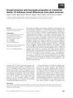
Micellar strand
FIGURE 2.3. Section of a plant fibre cell membrane showing a cellulose synthase enzyme complex
synthesising a micellar strand. From Salisbury and Ross (1992).
FIGURE 2.4. Depiction of the fringe-micellar theory showing how crystalline and amorphous regions are
repeatedly located next to each other along the cellulose microfibril. From Siau (1995).
Hemicellulose is a heterogeneous group of polysaccharides with a composition that varies between
different types of plant fibres and includes a range of carbohydrates, such as glucose, galactose,
mannose, xylose and arabinose. Compared to cellulose, the hemicellulose polymers are generally
characterised by being short (a maximum of 150 units), non-linear and more branched. Examples
of hemicelluloses are: (i) branched chains, such as carbon (1-4)-linked xyloglucan or
galactoglucamannan, (ii) unbranched chains, such as carbon (1-4)-linked xylan or mannan, and (iii)
chains of carbohydrate units that are carbon (1-3)-linked and therefore are forming a helical
structure (O’Sullivan 1995).
Lignin is a highly branched polymer composed of phenylpropane units organised in a very complex
three-dimensional structure. In a chemical sense, lignin is rather reactive and therefore any method
applied to extract lignin from plant fibres is affecting its molecular composition and structure.
2.1.2 Cell wall organization
The exact structural organization of the chemical constituents in the cell wall is a much-debated
subject, however it is generally accepted that the three major polymers are not uniformly mixed, but
are arranged in separate entities (Figure 2.5). The hemicellulose polymers are thought to be bound
8
Plant fibre structure
Background
to the cellulose microfibrils by hydrogen bonds forming a layer around the fibrils, and these
cellulose/hemicellulose units are then encapsulated by lignin.
FIGURE 2.5. Model of the structural organisation of the three major constituents in the cell wall of wood
fibres. From Wadsö (1993).
In addition to the organisation of the chemical constituents, the structural complexity of the cell
wall is increased by being organised into a number of layers differing by the angle of the cellulose
microfibrils to the longitudinal fibre axis, the so-called microfibril angle (Figure 2.6). During
growth of a plant fibre, the cell wall consists only of one layer, the so-called primary layer. The
microfibrils in the primary layer are deposited predominantly in the transverse direction, and
because of the restraining effect of the microfibrils, this makes the fibre grow in the longitudinal
direction. However, as the fibre is elongating the early deposited fibrils are being reoriented into
the longitudinal direction and consequently when growth ends, the fibril orientation in the primary
layer is not confined to a single direction. This generally accepted model of plant fibre growth is
called the multi-net model (Niklas 1992).
In the classical interpretation of the deposition of the cell wall after growth has terminated, the
distinction is made between three secondary layers denoted S1, S2 and S3. In these layers the
microfibrils are arranged in helixes coiling around the longitudinal axis of the fibre with a constant
angle within each layer but with large angular shifts between the layers. The microfibril angle in
the S1 and S3 layers is large, meaning that the fibrils are oriented nearly transverse to the fibre axis.
The microfibril angle in the S2 layer is small, and therefore these fibrils are oriented more parallel
to the fibre axis. In wood fibres, the microfibril angle in the S2 layer is in the range 3-50° and in
bast fibres it is below 10° (see Table 2.5, p. 20). Since the S2 layer is by far the thickest layer,
including about 60-80% of the cell wall in wood fibres (Siau 1995), the small angle of the
microfibrils in this layer dictates the overall anisotropic properties of the fibres. This rather simple
model of the fibril orientation in the secondary layers has however been questioned by some recent
9
Background
Plant fibre structure
studies indicating the existence of intervening layers with a gradual change of the microfibril angle
forming a so-called helicoidal structure (Neville 1993).
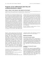
FIGURE 2.6. Cell wall layers in a plant fibre. M is the middle lamella connecting the fibres in the plant, P is
the primary layer, S1, S2 and S3 are the three secondary layers, and W is the cell membrane. From Siau
(1995).
2.2
PLANT FIBRE WATER SORPTION
The large water sorption capacity of plant fibres is an essential aspect of plant fibre composites. To
achieve an understanding of water sorption in the composites requires necessarily an understanding
of water sorption in the fibres themselves. However, only little information is presented on this
subject in the existing literature concerned with plant fibre composites. In contrast, in the field of
wood technology much research has been addressed to wood fibre water relations, and the
succeeding subsections are based on this work.
2.2.1 Physics of water
Basic knowledge of the physics of water is essential in relation to water sorption in plant fibres.
The water molecule is made from one oxygen atom and two hydrogen atoms held together by polar
covalent bonds. The polarity arises from the high electronegativity of the oxygen atom relative to
the hydrogen atoms, which causes the electrons of the covalent bonds to be located at a position
statistically closer to the oxygen than to the hydrogens. As a result, the covalent bonds are about 40
% ionic in character. The asymmetrical distribution of charges in water is the basis of formation of
10
Plant fibre water sorption
Background
hydrogen bonds between water molecules, but also between water molecules and polar groups in
other molecules, such as the hydroxyl groups (-OH) in the cell wall polymers of plant fibres.
To view the charge distribution within a water molecule various models have been proposed of
which the so-called ST2 model is a relative simple but descriptive model (Israelachvili 1991)
(Figure 2.7A). The ST2 model shows how two negative and two positive charges are located along
four tetrahedral arms radiating out from the centre of the oxygen atom with a mutual angle of 109°.
Thus, the water molecule can participate in four hydrogen bonds, and this allows for a tetrahedral
arrangement of water molecules to be formed (Figure 2.7B). This three-dimensional arrangement is
the main explanation for many of the special physical properties of water (e.g. high melting and
boiling point) compared to other molecules with similar low molecular weight and high polarity.
A
B
FIGURE 2.7. (A) The water molecules shown by the ST2 model (q=0.24 e; l=0.1 nm; θ=109°). (B) The
tetrahedral hydrogen bonded structure of water molecules. From Israelachvili (1991).
The strength of the hydrogen bonds between water molecules is relatively low (about 20 kJ/mol
compared to about 500 kJ/mol for covalent bonds) and because of molecular vibrations, the
hydrogen-bonded structure is highly labile with a constant formation and breaking of bonds
(Israelachvili 1991). Therefore, no specific water molecules are bound to one another for more than
a relative short time, yet a statistically constant fraction of molecules is joined together at all times
at a given temperature. By changes in temperature (the level of molecular kinetic energy), the
lifetime of the hydrogen bonds are changed and the equilibrium condition between fractions of
hydrogen bound water molecules and free water molecules are changed accordingly. Hydrogen
bound water molecules are defined as liquid water and free water molecules are defined as water
vapour. The fraction of water vapour is extremely small compared to the fraction of liquid water,
even at the boiling point the ratio is only 2 molecules per million (Skaar 1972). This small fraction
of water vapour exerts a pressure denoted as the saturated vapour pressure, which is an indirect
11
Background
Plant fibre water sorption
expression for the equilibrium condition that exists between fractions of liquid water and water
vapour at a given temperature. Except in closed systems, the actual vapour pressure of the
atmosphere is below the saturated vapour pressure and therefore liquid water is constantly
vaporised. Normally, air humidity is measured in terms of the relative humidity (RH), which is
defined as the ratio of the actual vapour pressure (p) and the saturated vapour pressure (p*):
RH = 100
p
p*
(2.1)
As mentioned above, the actual vapour pressure above an air-water interface will tend to move
towards the saturated vapour pressure. However, when water is trapped in small spaces, the
saturated vapour pressure is depressed. This is an important phenomenon in relation to water
sorption in porous materials, such as plant fibres, and will subsequently be explained. The affinity
between liquid water and a solid material is characterised by the contact angle at the water-material
interface, and the material is denoted hydrophilic when the angle is below 90° and hydrophobic
when the angle is above 90°. This can be recognised by observing the water surface close to the
walls of a container; if the container is made of a hydrophilic material (e.g. glass) the surface will be
curved in a downward direction with an angle given by the contact angle. By decreasing the radius
of the container into capillary dimensions (<100 µm) it can visualised that the water surface, the socalled meniscus, will attain a concave curved shape between the walls of the capillary and that the
radius of the curvature will depend on the contact angle (Figure 2.8). The curvature of a capillary
meniscus will shift the equilibrium condition between liquid water and water vapour towards liquid
water and thereby depress the saturated vapour pressure. Moreover, the increased area of the
curved meniscus relative to the flat meniscus represents an amount of work, which is equal to the
difference in hydrostatic pressure above and below the meniscus. The hydrostatic pressure is higher
above the meniscus, which means that capillary water is in tension. In relation to capillary water
sorption in plant fibres, this will tend to decrease the overall dimensions of the fibres. In Table 2.3
some numerical examples are presented of the relationship between the capillary radius, the
fractional depression of the saturated vapour pressure and the capillary pressure. The table shows
that only capillaries with radii smaller than about 10 µm will notably depress the saturated vapour
pressure and exert any capillary pressure. It can be realised that if the ambient relative humidity is
exceeding the fractional depression of the saturated vapour pressure, water vapour will condense
into liquid water; e.g. at an ambient relative humidity of 0.95 water vapour will condense into
capillaries with radii below 0.020 µm.
12
Plant fibre water sorption
Background
θ
FIGURE 2.8. Drawing of a capillary meniscus. θ is the contact angle between water and the material of the
capillary wall.
TABLE 2.3. Relationship between capillary radius, fractional depression of the saturated vapour pressure
and capillary pressure. Data are from Skaar (1972) and are based on the Kelvin equation and the capillarpressure equation.
Capillary radius
(µm)
10.4
1.0
0.103
0.034
0.020
0.012
0.010
Fractional
depression of p*
Capillary pressure
(kPa)
1.0000
0.9999
0.999
0.99
0.97
0.95
0.92
0.90
0
15
140
1400
4200
7100
11600
14600
2.2.2 Water sorption
The traditional definition of water content in plant fibres is based on gravimetric measurements of
the dry fibre mass (m0) and the moist fibre mass (mRH):
u RH =
U RH m RH − m 0 m w
=
=
100
m0
m0
(2.2)
where u is fractional water content, U is water content in percentage (%), mw is mass of sorped
water, and the subscript RH denotes that the moist fibre mass is determined at a given ambient
relative humidity.
Water can exist in plant fibres in three different forms: (i) water bound by hydrogen bonds to the
various sorption sites in the cell wall, subsequently referred to as bound water, (ii) free liquid water
13