Tài liệu Báo cáo "Effect of the preparation conditions on the properties of Fe-Pt nanoparticles produced by sonoelectrodeposition " pptx
Bạn đang xem bản rút gọn của tài liệu. Xem và tải ngay bản đầy đủ của tài liệu tại đây (150.92 KB, 7 trang )
VNU Journal of Science, Mathematics - Physics 25 (2009) 1-7
1
Effect of the preparation conditions on the properties of Fe-Pt
nanoparticles produced by sonoelectrodeposition
Nguyen Hoang Luong*
, Nguyen Hoang Hai, Nguyen Dang Phu
Center for Materials Science, Faculty of Physics, College of Science, VNU
334 Nguyen Trai, Hanoi, Vietnam
Received 10 Macrh 2009
Abstract. Fe-Pt materials have been widely prepared by vacuum evaporation technique. Recently,
chemical and physicochemical methods have been successfully used to make Fe-Pt nanoparticles,
thin films. This paper reported another physicochemical method, namely sonoelectrodeposition, to
produce Fe-Pt nanoparticles. In the sonoelectrodeposition, the electrodeposition process was
assisted with a sonicator. The Ti horn of the sonicator played a role as the cathode on which Fe-Pt
nanoparticles were deposited. After a certain time of deposition, a sonic pulse was applied to
remove the particles from the Ti cathode. The composition of Fe-Pt particles can be controlled by
changing the concentration of Fe and Pt ions in the electrolyte and the deposition voltage. The
particle size can be adjusted by the time of deposition. The as-deposited Fe-Pt nanoparticles were
ferromagnetic at room temperature. Upon annealing at 700°C for 1 h under H
2
atmosphere, the
saturation magnetization and the coercivity of the nanoparticles were improved significantly.
Sonoelectrodeposition is a promising technique to make large quantity of Fe-Pt nanoparticles.
Keywords: FePt; L1
0
structure; sonoelectrodeposition; magnetic nanoparticles; hard magnetic
materials
1. Introduction
FePt alloy can be in either a disordered face-centered cubic (fcc) phase in which the statistical
distribution of the Fe and Pt atoms is substitutionally random, or in a partially or completely ordered
face-centered tetragonal (fct) phase in which Fe and Pt atoms occupy specific sites. The ordered phase
can change to the disordered phase and vice versa at elevate temperatures [1]. The fct FePt alloy
possesses excellent hard magnetic properties with the saturation magnetization,
µ
0
M
s
, of 1.4 T, the
Currie temperature, T
c
, of 750 K, and the crystalline anisotropy K
1
, of 7 MJ/m
3
[2]. Despite the high
cost of Pt, FePt thin films or particles have been paid much attention for their use as ultrahigh density
magnetic storage media and microelectronic mechanical system (MEMS) due to the mechanical and
chemical stability of the ordered fct L1
0
structure. Beside the equiatomic composition FePt, the Fe
3
Pt
and FePt
3
with L1
2
structure and less preferred magnetic properties can exist. The ordered FePt
materials are normally obtained from the disordered materials via the order-disorder transition. But
______
*
Corresponding author. Tel.: (84-4) 38582216
E-mail:
N.H. Luong et al. / VNU Journal of Science, Mathematics - Physics 25 (2009) 1-7
2
sometimes the ordered phase can be obtained from pure Fe and Pt layers via the diffusion of the two
materials at high temperatures [3].
There are several ways to make FePt nanostructured materials including physical techniques such
as mechanical deformation [3], arc-melting [4], vacuum evaporation (sputtering, thermal evaporation)
[5, 6], laser ablation pulse [7], chemical methods [8-10], and physicochemical method such as
electrodeposition [11, 12]. Up to now, the vacuum evaporation is the most used method.
Electrodeposition is a promising way to obtain FePt thin films because it is less expensive than
physical methods, less complicated than chemical methods. But by this technique, it is difficult to get
nanoparticles with large quantity. Sonoelectrochemistry was developed to make nanoparticles [13]. It
combined the advantages of sonochemistry and electrodeposition. Sonochemistry is a very useful
synthetic method which was discovered as early as 1934 that the application of ultrasonic energy
could increase the rate of electrolytic water cleavage. The effects of ultrasonic radiation on chemical
reactions are due to the very high temperatures and pressures, which develop in and around the
collapsing bubble [14]. Sonoelectrochemistry has the potential benefit of combining sonochemistry
with electrochemistry. Some of these beneficial effects include acceleration of mass transport,
cleaning and degassing of the electrode surface, and an increased reaction rate [15]. In this paper, we
report the use of the sonoelectrochemical method for the preparation of FePt nanoparticles.
2. Experimental
The sonoelectrochemical device employed is similar to that described in ref. [16]. A titanium horn
with diameter of 1.3 cm acted as both the cathode and ultrasound emitter (Sonics VCX 750). The
electroactive part of the sonoelectrode was the planar circular surface at the bottom of the Ti horn. An
isolating plastic jacket covered the immersed cylindrical part. This sonoelectrode produced a sonic
pulse that immediately followed a current pulse. One pulse driver was used to control a galvanostat
and the ultrasonic processor, which was adapted to work in the pulse mode. A home-made galvanostat
(without using a reference electrode) was used to control the constant current regime. A platinum plate
with a square of 1 cm
2
was used as a counter electrode. The current pulse was changed from 15 to 30
mA/cm
2
. The ultrasound power density was 100 W/cm
2
. The duration t
on
of the current pulse was 0.5 –
0.8 s then the current was turned off for a fixed duration t
off
of 0.5 s. During t
on
, FePt nanoparticles
were deposited on the surface of the electrode When the current was switched off, an ultrasound was
activated to remove the nanoparticles from the electrode. The time of ultrasound was 0.2 s for all
samples. The temperature during the reaction was room temperature. The volume of the electrolysis
cell was 80 ml containing 1 mM/l H
2
PtCl
6
, 0.1 M/l FeSO
4
, and 0.525 M/l Na
2
SO
4
. The chemicals were
mixed under N
2
atmosphere. The pH = 3 of the solution was controlled by H
2
SO
4
. After deposition,
FePt nanoparticles were collected by using a centrifuge (Hettich Universal 320, 9000 RPM, 20 min).
Nanoparticles were dried in air at 80°C for 20 min. All samples were annealed at 700°C for 1 h under
H
2
atmosphere. The structure of the nanoparticles was analyzed by using a Bruker D5005 X-ray
diffractometer (XRD). Magnetic measurement was conducted by using a DMS-880 sample vibrating
magnetometer (VSM) with maximum magnetic field of 13.5 kOe at room temperature. The particle
morphology was obtained from a transmission electron microscope (TEM JEM1010-JEOL). The
chemical composition of the Fe-Pt nanoparticles was studied by using an energy dispersion
spectroscopy (EDS OXFORD-ISIS 300). The thermal behaviour was examined by a differential
scanning calorimetry (DSC, STD 2960 TA Instruments) over the temperature range of 25–750°C with
heating rates of 10°C/min under flowing argon.
N.H. Luong et al. / VNU Journal of Science, Mathematics - Physics 25 (2009) 1-7
3
3. Results and discussion
The chemical composition of the Fe-Pt nanoparticles was controlled by adjusting the current
density (corresponding to the applied voltage). When the current density of 15 – 20 mA/cm
2
, the
composition of nanoparticles was close to the expected equiatomic composition (Table 1). At higher
current densities, the atomic percent of Fe was higher because the standard electrode potential Fe
2+
/Fe
(-0.44 V [17]) is more negative than that of Pt
4+
/Pt (0.742 V [18]).
Table1.Chemical composition, magnetic properties of the samples. J is the current density; t
on
is the deposition
time of a pulse; Fe, Pt are the atomic percent of Fe and Pt in the samples, respectively; H
c
is the coercivity; M
s
is
the magnetization at 13.5 kOe); M
r
/M
s
is the magnetic squareness
Name J
(mA/cm
2
)
t
on
(s)
Fe
(at. %)
Pt
(at. %)
H
c
(kOe)
M
s
(emu/g)
M
r
/M
s
S1 30 0.5 69 31 5.0 40 0.26
S2 25 0.5 61 39 6.0 45 0.36
S3 20 0.5 52 48 6.1 49 0.41
S4 15 0.5 45 55 8.5 23 0.70
S5 15 0.6 - - 9.1 24 0.72
S6 15 0.7 - - 8.5 30 0.4
S7 15 0.8 - - 8.7 43 0.4
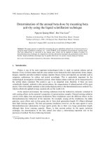
Figure 1 is the TEM images of typical as-prepared and annealed samples. Particle size of the as-
prepared FePt sample was 5 – 10 nm. After annealing the particle size increased to 10 – 25 nm due to
the aggregation and particle growth. In addition, the size distribution of the annealed particles was
larger than that of the as-prepared samples.
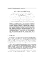
Figure 2 shows the XRD patterns of the as-prepared and the annealed S4 nanoparticles (700°C for
1 h). Before annealing, the XRD results showed the reflections of pure Pt structure, which is similar to
other FePt thin films produced by electrodeposition [19]. However, authors in Ref. [19] thought that
the reflections were from the disordered fcc phase. For the fcc phase, XRD results present only the
fundamental reflections which are (111), (200), and (220). The fundamental reflections of the fcc FePt
are close to the (111), (200), and (220) reflections of the Pt that make some scientists thought that they
are of the fcc structure. We propose that XRD results from our as-prepared nanoparticles and from
Ref. [19] are the peaks of only Pt. The reflections from Fe are very weak due to the fact that their
Fig. 1. TEM images of the as-prepared (left) and annealed (right) FePt
nanoparticles (700°C/1 h).
N.H. Luong et al. / VNU Journal of Science, Mathematics - Physics 25 (2009) 1-7
4
atomic weight is much less than that of Pt which is similar to the XRD result of FePt foils prepared by
cold deformation [20]. The Pt peaks in the as-prepared samples are broad due to the small size of the
particles. Using the Scherrer formula with the full width at half maximum of the strongest peak (111),
the mean particle size of Pt particles was deduced to be 5.2 nm which is much smaller than the particle
size obtained from the TEM image. The particles were not disordered FePt but they can be formed by
many small domains of pure Fe and Pt. The formation of FePt by electrodeposition was not occurred
and may be ascribed to the large difference in the standard electrode potential of the Fe
2+
/Fe and
Pt
4+
/Pt. Upon annealing, the formation of the ordered L1
0
fct phase happened by the diffusion process
between Fe and Pt domains.
0 100 200 300 400 500 600 700
-30
-20
-10
Heat Flow (W/g)
T (
0
C)
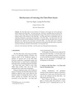
Fig. 3. DSC trace for the FePt nanoparticles (heating rate 10°C/min).
Figure 3 presents the DSC trace for the FePt nanoparticles in the temperature range from 25°C to
750°C. There was a broad peak located at about 350°C. It is known that if there is a order-disorder
transformation, i.e., the transformation of the disordered fcc to the ordered fct phase, there will be a
sharp peak in the range from 367°C – 440°C with the full width at half maximum of 56°C – 120°C on
the heat flow [21]. The broad peak on the DSC trace in the FePt nanoparticles suggests that there was
no such transition in the FePt nanoparticles upon annealing. The formation of the L1
0
FePt phase was
20 30 40 50 60 70
*
*
Intensity (arb. unit)
2θ (degree)
(111)
f
(200)
f
(002)
f
(110)
s
(001)
s
(201)
s
(112)
s
(220)
f
*
As-prepared
Annealed
Fig. 2. XRD patterns (Cu Kα radiation) of the as-prepared (bottom) and annealed (top)
nanoparticles compared to those of the intensities for L1
0
FePt (pdf file 431359) and for
Pt (marked by the astericks, pdf file 04-0802). The fundamental peaks of FePt structure
were denoted by “f” and the superlattice peaks were denoted by “s”.
N.H. Luong et al. / VNU Journal of Science, Mathematics - Physics 25 (2009) 1-7
5
via the diffusion process of Fe and Pt domains because the diffusion occurred at any temperature. Both
fundamental and superlattice reflections of the L1
0
phase were presented in Fig. 2. There was a small
peak next to the (111) main peak of the L1
0
FePt which can be assigned to the Pt-rich FePt phase –
FePt
3
. The presence of this phase can be explained by the incomplete diffusion between Fe and Pt
domains
Magnetic measurements revealed low saturation magnetization (M
s
) and coercivity (H
c
) in all as-
prepared samples (data not shown). The saturation magnetization of the unannealed particles was
about few emu/g and the coercivity was 20 – 80 Oe. The low value of M
s
of the as-prepared
nanoparticles may be explained by the oxidation or hydroxidation of Fe atoms in nanoparticles which
can result in the weak magnetic iron oxides and iron hydroxides. This is in agreement with the
suggestion of separated Fe and Pt domains in as-prepared nanoparticles. It is known that FePt with
high saturation magnetization is a chemically stable material. Therefore it is difficult to be oxidized to
form weak ferromagnetic materials After annealing the hard magnetic FePt phase was formed. Figure
4 presents the magnetic curve of the annealed S4 as an example. The curve shows a typical hard
magnetic hysteresis loops with high H
c
. Note that, because of the limit of maximum applied field of
13.5 kOe, the curve is a minor loop. Therefore, the real coercivity must be higher than those obtained
from the hysteresis curves. However, the loop shows a kink at low reversed magnetic field of 500 Oe,
which is indicates that there was a small amount of a soft magnetic phase. Classically, the coercivity is
defined as the field for which the magnetization (M) vanishes (H’
c
). In a more physically meaningful
definition, the coercivity H
c
may be defined as the field where the largest number of moments
reverses, i.e., the maximum of the susceptibility (dM/dH). In most cases, both definitions of the
coercivity are almost equivalent. However in multiphase materials, two definitions are significantly
different [22]. From Fig. 4, H’
c
was 6 kOe whereas H
c
was 8.5 kOe. The values of all studied samples
are given in Table 1 and Fig. 5. Coercivity gets maximum value (equal or higher than 8.5 kOe) in the
samples with the chemical composition of the particles close to the equiatomic composition, i.e.,
samples S4 – S7. Magnetization at the highest applied field (13.5 kOe), M
s
, and the magnetic
squareness (defined as M
r
/M
s
, where M
r
is the remanent magnetization) of S4 are 23 emu/g and 0.70,
respectively. Similar magnetic properties have been obtained for other samples. When the current
density J reduced, the coercivity increased and with J = 15 mA/cm
2
, H
c
was equal or larger than 8.5
kOe and almost did not change significantly with t
on
. This is because with J = 15 mA/cm
2
, the
chemical composition of nanoparticles are close to the equiatomic composition. The atomic percent of
Fe increased with J which resulted in the high M
s
(samples S1 – S3) as shown in Table 1. However,
-10000 -5000 0 5000 10000
-30
-20
-10
0
10
20
30
0.000
0.002
0.004
0.006
0.008
0.010
M
M (emu/g)
H (Oe)
8500
6000
500
dM/dH
dM/dH (emu/g.Oe)
Fig. 4. Magnetic curves of sample S4. The maximum
applied field was 13.5 kOe.
N.H. Luong et al. / VNU Journal of Science, Mathematics - Physics 25 (2009) 1-7
6
the magnetic squareness M
r
/M
s
reduced with J because of the presence of the Fe
3
Pt. Of cause, the kink
in the magnetic curves was more evident in the samples with high Fe content.
In another series of samples, we fixed the current density and change the deposition time t
on
. We
thought that by changing t
on
, the size of particles would change and therefore the magnetic properties
of the particles would be affected. After annealing, H
c
did not change with t
on
as significantly as M
s
did. The coercivity of S4 – S7 was in the range from 8.5 kOe to 9.1 kOe (Table 1 and Fig. 5). This can
be explained by the fact that the chemical composition mainly depended on the current density.
Magnetic properties of the samples S4 and S5 were almost the same. Sample S5 showed the most
preferred hard magnetic properties. The magnetic squareness showed a sudden drop and M
s
showed a
strong change when the deposition time was longer than 0.6 s as shown in sample S6 and S7 which
presented strong ratio of a soft magnetic phase. In our experiment, we only used 0.08 mM
(corresponding to 1 mM/l) Pt
4+
in a bath of 80 ml which was enough to make about 20 mg FePt
nanoparticles. For long deposition time, the concentration of Pt
4+
in the electrolyte reduced
significantly with time. Therefore, there were more Fe
2+
ions deposited on the Ti horn than Pt
4+
ions.
As the result, there can be more Fe in samples S6 and S7 which caused their low magnetic squareness
and high M
s
.
4. Conclusion
Sonoelectrochemistry is a promising method to make FePt magnetic nanoparticles. FePt
nanoparticles made by this technique had the size of 10 - 20 nm. After annealing, the nanoparticles
30 25 20 15
3
4
5
6
7
8
9
0.0
0.2
0.4
0.6
0.8
1.0
S4
S3
S2
Magnetic Squareness
H
c
(kOe)
J (mA/cm
2
)
Coercivity H
c
S1
t
on
= 0.5 s
Magnetic squareness
0.5 0.6 0.7 0.8
4
5
6
7
8
9
10
0.3
0.4
0.5
0.6
0.7
0.8
0.9
S7
S6
S5
Magnetic squareness
H
c
(kOe)
t
on
(s)
Coercivity H
c
S4
Magnetic squareness
J = 15 mA/cm
2
Fig. 5. Dependence of magnetic squareness and coercivity on current
density J (top) and deposition time t
on
(bottom).
N.H. Luong et al. / VNU Journal of Science, Mathematics - Physics 25 (2009) 1-7
7
showed a high coercivity of 9.1 kOe at room temperature. This method possesses some advantages
compared to common methods such as simple preparation, low-cost equipment and easy scale-up.
Acknowledgments. This work is supported by the Key Project QGTD.08.05 of Vietnam National
University, Hanoi and the European Commission Project Selectnano-TTC (Contract No. 516922). The
authors would like to thank Prof. Le Van Vu for XRD measurements and Mr. Pham Van Dinh for
experimental assistance.
References
[1] J.P. Liu, C.P. Kuo, Y. Liu, D.J. Sellmyer, Appl. Phys. Lett. 72 (1998) 483.
[2] A. Cebollada, R.F.C. Farrow, M.F. Toney, in: H.S. Nalwa (Ed.), Magnetic Nanostructure, American Scientific, (2002)
93.
[3] N.H. Hai, N.M. Dempsey, M. Veron, M. Verdier, D. Givord, J. Magn. Magn. Mater. 257 (2003) L139.
[4] Q.I. Xiao, P.D. Thang, E. Brück, F.R. de Boer, and K.H.J. Buschow, Appl. Phys. Lett. 78 (2001) 3672.
[5] N.T.T. Van, N.H. Hai, N.H. Luong, V.V. Hiep, N. Chau, J. Korean Phys. Soc. 52 (2008) 1435.
[6] N.H. Luong, V.V. Hiep, D.M. Hong, N. Chau, N.D. Linh, M. Kurisu, D.T.K. Anh, G. Nakamoto, J. Magn. Magn.
Mater. 290-291 (2005) 559.
[7] L.J. Qiu, J. Ding, A.O. Adeyeye, J.H. Yin, J.S. Chen, S. Goolaup, N. Singh, IEEE Trans. Magn. 43 (2007) 2157.
[8] S. Saita, S. Maenosono, Chem. Mater. 17 (2005) 3705.
[9] R. Harpeness, A. Gedanken, J. Mater. Chem. 15 (2005) 698.
[10] S. Sun, C.B. Murray, D. Weller, L. Folks, A. Moser, Science 287 (2000) 1989.
[11] K. Žužek Rožman, A. Krause, K. Leistner, S. Fähler, L. Schultz, H. Schlörb, J. Magn. Magn. Mater. 314 (2007) 116.
[12] F.M.F. Rhen, G. Hinds, C. O'Reilly, J.M.D. Coey, IEEE Trans. Magn. 39 (2003) 2699.
[13] A. Gedanken, in D. Bahadur, S. Vitta, O. Prakash (Ed.), Inorganic Materials: Recent Advances, (2004) 302.
[14] K.S. Suslick, S.B. Choe, A.A. Cichowlas, M.W. Grinstaff, Nature 354 (1991) 414.
[15] T.J. Mason, J.P. Walton, D.J. Lorimer, Ultrasonics 28 (1990) 333.
[16] J.J. Zhu, S.T. Aruna, Yu. Koltypin, A. Gedanken, Chem. Mater. 12 (2000) 143.
[17] P. Atkins, Physical Chemistry, (1997) 6th edition (W.H. Freeman and Company, New York).
[18] A.J. Bard, L.R. Faulkner, Electrochemical Methods. Fundamentals and Applications, 2001, 2nd edition (John Wiley
and Sons Inc).
[19] Q. Zeng, Y. Zhang, H.L. Wang, V. Papaefthymiou, G.C. Hadjipanayis, J. Magn. Magn. Mater. 272-276 (2004) e1223.
[20] N.H. Hai, N.M. Dempsey, D. Givord, J. Magn. Magn. Mater. 262 (2003) 353.
[21] J. Lyubina, O. Gutfleisch, Ralph Skomski, K H. Muller, L. Schultz, Scripta Mater. 53 (2005) 469.
[22] D. Givord and M.F. Rossignol, Coercivity, in J.M.D. Coey (Ed.), Rare-earth Iron Permanent Magnets, 1996,
Clarendon Press: Oxford, p. 218.