PETROMODELER (Petrological Modeler): a Microsoft® Excel© spreadsheet program for modelling melting, mixing, crystallization and assimilation processes in magmatic systems
Bạn đang xem bản rút gọn của tài liệu. Xem và tải ngay bản đầy đủ của tài liệu tại đây (2.1 MB, 11 trang )
Turkish Journal of Earth Sciences
/>
Research Article
Turkish J Earth Sci
(2013) 22: 115-125
© TÜBİTAK
doi:10.3906/yer-1104-6
PETROMODELER (Petrological Modeler): a Microsoft® Excel© spreadsheet program for
modelling melting, mixing, crystallization and assimilation processes in magmatic systems
Emrah Yalçın ERSOY*
Dokuz Eylül University, Faculty of Engineering, Department of Geology, TR-35160, Buca-İzmir, Turkey
Received: 09.04.2011
Accepted: 14.10.2011
Published Online: 04.01.2013
Printed: 25.01.2013
Abstract: PETROMODELER (Petrologic Modeler) is a Microsoft® Excel© spreadsheet program which numerically and graphically
models magmatic processes including melting, crystallization, assimilation and mixing by using trace elements and isotopic ratios.
Melting models include (a) batch, (b) dynamic (continuous) and (c) fractional melting for (1) instantaneous and (2) cumulate melts,
(3) residual solid and (4) total residue. These models can also be used to treat modal and non-modal melting. Crystallization processes
modelled in the program include: (1) perfect equilibrium and (2) perfect fractional crystallization (PEC and PFC), (3) equilibrium
crystallization-imperfect fractional crystallization (EC-IFC), (4) zoned crystallization-imperfect fractional crystallization (ZC-IFC),
and (5) combined assimilation and fractional crystallization (AFC). Mixing between two end-member compositions can also be
modelled by the program. The main advantages of the program are that; (1) crystallization and mixing processes can be performed on a
starting composition which may be chosen from; (a) any melting model result, or (b) any sample composition entered into the “samples”
tables, (2) the results of any model can be exported as a graphic file (GIF) and as tables, (3) changes in any parameters are simultaneously
updated onto all diagrams and tables. PETROMODELER also calculates other useful parameters, such as normative mineralogy, Mg#,
Eu/Eu*, εSr and εNd, σ(DM) (depleted mantle Nd model ages) of a given sample. Some classification diagrams for volcanic rocks are also
included in the program. Conversion of element abundances on the basis of wt% and ppm can also be performed.
Key Words: Geochemical modelling, magmatic petrology, trace elements, melting, crystallization, magma mixing
1. Introduction
Geochemical compositions of magmatic rocks result from
several petrological processes which are developed during:
(1) primary processes, such as partial melting of the source
rocks, (2) secondary processes, such as crystal separation,
wall-rock assimilation, combined crystal separation
and wall-rock assimilation, and mixing of two different
magmas. These processes can be numerically modelled
using major and trace element contents and isotopic ratios
of magmatic rocks. Quantitative models for these processes
have been formulized by several workers (see Schilling
& Winchester 1967; Anderson & Greenland 1969; Shaw
1970; Langmuir et al. 1977; DePaolo 1981; McKenzie 1985;
O’Hara 1993; Ozawa & Shimizu 1995; Shaw 2000; Ozawa
2001; Zou 1998, 2007; Nishimura 2009). Using these
formulas generally requires fast computer systems as they
are often complex and include many parameters. Several
types of computer software have been employed in order
to perform the numerical models of petrological processes
(Keskin 2002, Petrelli et al. 2005; Ersoy & Helvacı 2010),
but they largely deal with either certain melting processes
or FC/AFC processes. Among the different computer
*Correspondence:
modelling approaches, spreadsheet programs have some
advantages, as they are easier and faster to use during data
conversion, storing, and evaluation.
In this study, I present a Microsoft® Excel© spreadsheet
program that can be used for nearly all of the petrological
processes outlined above, and includes trace and major
elements and isotopes. The program has also some useful
features, allowing the user to classify magmatic rocks and
to quickly calculate useful parameters, such as normative
mineralogical compositions.
2. Overview of magmatic processes
Magmatic rocks are formed through melting,
crystallization, contamination and mixing processes over
a range of depths in the asthenosphere and lithosphere.
These different processes may develop in several ways,
and may accompany one another. The term “melting”
refers to melt production from a source rock due to
increasing temperature, decreasing pressure, addition
of volatile components, or by a combination of these
processes. Melting of a source rock develops gradually
(partial melting) and can be quantitatively indicated by
115
ERSOY / Turkish J Earth Sci
the percentage melting. The chemical composition of the
melt produced by partial melting is controlled by: (1) the
chemical and (2) mineralogical composition of the source
rock, and (3) the degree of partial melting. The partial
melts may subsequently undergo crystallization processes
in magma chambers emplaced at different lithospheric
levels, as their temperature decreases. During the cooling
of a magma body, some minerals begin to crystallize and
may separate from the liquid body. This process also
changes the initial major and trace element composition
of the magma. Both melting and crystallization
processes may be developed under equilibrium or
disequilibrium conditions, depending on whether or not
the liquid remains in connection with the solid phase.
The crystallization processes may also be accompanied
by wall-rock assimilation (contamination), giving rise to
further changes in the magma composition. Furthermore,
different magma bodies may mix to yield a new magma
composition intermediate between two initial magmas.
In this section, I briefly summarized the main magmatic
processes that can be numerically modeled using the
PETROMODELER program to describe trace element and
isotope compositions.
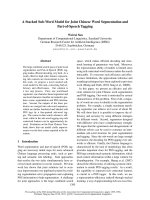
2.1. Melting processes
There are three main models based on chemical
equilibrium between the remaining solid (the restite) and
melt that is produced: (a) batch melting, (b) fractional
melting, and (c) dynamic melting (Figures 1 and 2).
These processes can develop as open- or closed-systems,
depending on whether or not material exchange occurs
with the surrounding rocks. The reader is referred to
Schilling & Winchester (1967), Shaw (1970), Langimur
et al. (1977), McKenzie (1985), Ozawa & Shimizu (1995),
Ozawa (2001) and Zou (1998, 2007) for further reading
on dynamics and quantitative modelling of melting
process. PETROMODELER numerically models trace
RESIDUAL
SOLID plus
MELT
Fractional
melting
RESIDUAL
SOLID
Dynamic
melting
RESIDUAL
SOLID plus
RESIDUAL
MELT
+
+
Figure 1. Cartoon showing closed-system melting models (after
Zou 1998).
116
(1)
m
where, C 0 is the concentration of the trace element
in the source rock (starting composition), D0 is the
bulk partition coefficient of the trace element, F is the
fraction of liquid produced during melting. Bulk partition
coefficients are calculated from;
(2)
where, D is the partition coefficient of ith element in jth
mineral, and W is the proportion of jth mineral in the
source.
P0 = D 0
Φ=0
ACCUMULATED
MELTS
SOLID
SOURCE
Non-modal
fractional melting
Closed-system melting models
Batch
melting
element compositions on the basis of their bulk partition
coefficients and initial abundances; isotopic ratios are
not changed during closed-system melting models.
Differentiation of major elements by melting is not
modelled by PETROMODELER.
2.1.1. Batch (equilibrium) melting
The batch melting (or equilibrium melting) model is the
simplest process and assumes that the melt remains in
chemical equilibrium with the solid during melting (Figure
1) (Schilling & Winchester 1967; Shaw 1970; Zou 1998).
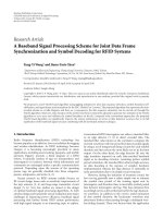
Any melting model (batch model and the others hereafter)
may develop as “modal” or “non-modal”. During “modal
melting”, the proportion of minerals that undergo melting
is the same as that in the source. In “non-modal (eutectic)
melting” models, the mineral proportions in the melt are
different from that of the source as some minerals melt
preferentially. Modal melting normally does not happen
in nature.
The trace element compositions of instantaneous (or
m
m
accumulated) melt ( C I or C L , respectively) produced
by modal batch melting are given by;
Φ=0
Non-modal
dynamic melting
Φ
Modal
fractional melting
P0 = D 0
Φ
1
Non-modal
batch melting
Modal
dynamic melting
P0 = D 0
1
Modal
batch melting
Figure 2. Cartoon showing relationships between different
melting models (after Zou 1998).
ERSOY / Turkish J Earth Sci
During non-modal partial melting, the bulk partition
coefficients of many trace elements change, as some
minerals (such as garnet and clinopyroxene in mantle
lherzolite) are consumed preferentially. The trace element
compositions of any instantaneous or accumulated melts
m
produced by the non-modal batch melting model ( C I or
m
C L , respectively) are given by;
(3)
where, P0 is the bulk partition coefficient of the trace
element of the minerals entering the melt. The other
parameters are the same as previously described. P0 is
calculated from;
(4)
where, P is the weight fraction of the jth mineral entering
the melt phase.
The trace element compositions in the residual solid
m
m
(or total residue) ( C S or C R ) during modal and nonmodal batch melting are, in turn, expressed by;
(5)
(6)
When P0 = D0, the non-modal melting equation is
equivalent to modal melting. Relationships between
different melting models are summarized in Figure 2.
2.1.2. Fractional melting
The fractional melting, another end-member of the melting
models, assumes that the melt is removed from the residual
source as soon it is formed. In the fractional melting model,
only the last drop of liquid is in equilibrium with the final
portion of restite, and there is no residual melt (Figure 1)
(Gast, 1968; Schilling & Winchester 1967; Shaw 1970; Zou
1998). The concentration of any trace element in the melt
can be calculated for two types of melt: instantaneous and
accumulated. The concentration of any trace element in
m
m
the instantaneous ( C I ) and accumulated ( C L ) melts
during modal fractional melting is, in turn, expressed by:
The trace element composition of the residual solid
(which equivalent to total residue) during modal fractional
melting is expressed by:
(9)
The trace element composition of the instantaneous
melt, accumulated melt and the residual material during
non-modal fractional melting are, in turn, expressed
by:
(10)
(11)
2.1.3. Dynamic (continuous or critical) melting
Dynamic melting involves the retention of a critical
fraction of melt in the restite. The amount of this fraction
depends on the critical mass porosity of the source rock.
Therefore, this model is intermediate between the two
end-member models of batch and fractional melting
(Figure 1). The advantage of this model is that it may
explain the fractionation of some strongly incompatible
elements (Langmuir et al. 1977; Wood 1979; Maaløe
1982; McKenzie 1985; Zou 1998). In this model, no melt
extraction occurs (as in batch melting) when the mass
porosity of the restite (melt mass fraction, y) is less than
the critical mass porosity of the residue (the critical value
for separation, F).
The trace element compositions of the instantaneous
and accumulated melts produced by modal dynamic
melting are, in turn, expressed by:
(13)
(14)
where,
(7)
[
[
(8)
(15)
The equations for trace element compositions in the
instantaneous and accumulated melts produced by nonmodal dynamic melting are, in turn:
117
ERSOY / Turkish J Earth Sci
(21)
where D is the bulk partition coefficient during partial
melting, which is different from the initial bulk partition
coefficient in the source (D0). D is expressed by:
(16)
D=
D 0 - (P0 6 X + U (1–X )@
D 0 - FP0
1 –P =
(1–X) (1–U)
Therefore,
(17)
The concentration of any element in the residual
m
m
solid ( C S ) and total residue ( C R ) is similar for batch
and fractional melting models. However, these differ
for the dynamic melting models; the concentration in
the total residue is related to the concentration in the
residual solid and the concentration in the residual melt.
The concentration in the residual melt during melting is
equivalent to that of instantaneous melt.
The trace element composition of the residual solid
during modal dynamic melting is expressed by:
(22)
(23)
The trace element compositions of the total residue
m
( C R ) is expressed by:
(18)
The concentration in the total residue is related
through:
(19)
Therefore, the trace element composition of the total
residue during modal dynamic melting is expressed by:
The trace element compositions of the residual solid
m
( C S ) during non-modal dynamic melting are expressed
by;
118
(24)
2.2. Crystallization and contamination processes
As the melt cools, it begins to crystallize. Each mineral
phase derived from the liquid has a different crystallization
temperature, also depending on other parameters, such as
chemical composition and pressure. For example, at low
pressures, olivine is usually the first phase to crystallize
from basic (low-SiO2) melts. Crystallization processes in
this study are considered to be developed in closed-systems;
i.e., no material input occurs during crystallization. Only
the assimilation and fractional crystallization model (AFC)
acts as an open-system. PETROMODELER numerically
models trace element compositions for all the crystallization
models summarized below. Isotopic ratios are not changed
during close-system crystallization models. Major element
differentiation during crystallization processes can only
be applied to perfect fractional crystallization (PFC)
processes by PETROMODELER.
2.2.1. Perfect equilibrium crystallization (PEC)
If all the crystallized solid phases remain in the liquid,
they can be assumed to stay in chemical equilibrium with
ERSOY / Turkish J Earth Sci
the magma. This process is known as Perfect Equilibrium
Crystallization (PEC). The trace element composition of
PEC
the liquid phase during PEC (C lc ) is expressed by:
(25)
f
where, C 0 is the initial trace element composition of
the magma, F is the mass fraction of the residual magma
relative to the initial mass, and D0 is the bulk partition
coefficient for the fractionating mineral assemblage which
is calculated by Eq. (2).
2.2.2. Perfect fractional crystallization (PFC)
If the early formed mineral phase is continuously and
perfectly removed from the initial liquid, both the major
and trace element composition of the initial melt would be
differentiated from the PEC model. This process is termed
Perfect Fractional Crystallization (or Rayleigh fractionation,
Rayleigh (1896)). The trace element composition of the
remaining liquid phase during fractional crystallization
PEC
(C lc ) is expressed by:
(26)
Major element differentiation during PFC can also
be modelled by PETROMODELER. This is based on the
major element compositions of fractionated minerals,
instead of their partition coefficients. The weighted
major element composition of the fractionated mineral
assemblage is calculated in a similar way to that shown by
Eq. (2), and then subtracted from the initial major element
f
composition ( C0 ) on the basis of fractionation ratio (F).
2.2.3. Equilibrium crystallization and imperfect
fractional crystallization (EC-IFC)
The Rayleigh fractionation equation (Eq. 22; Rayleigh
1896) is only valid for perfect crystal separation from the
liquid. However, this excludes crystals that are removed
in infinitesimally small batches. Note that crystal-liquid
separation is generally imperfect in nature (e.g., Anderson
& Greenland 1969; O’Hara 1993, Nishimura 2009). IFC
is particularly useful in explaining the variation of highly
compatible elements in basalts and their source rock
restite compositions. If it is assumed that there is perfect
equilibrium between the suspended crystals in the cooling
magma and imperfect separation of formed crystals, then
the suspended crystals do not develop chemical zoning.
In this case, trace element composition of the liquid phase
during equilibrium crystallization and imperfect fractional
crystallization (IC lcAFC ) is expressed by:
(27)
where, δ is the mass fraction of the suspended crystals.
2.2.4. Zoned crystallization and imperfect fractional
crystallization (ZC-IFC)
Natural volcanic rocks are often characterized by the
presence of zoned phenocrysts in the volcanic matrix
or glass, indicating that chemical equilibrium was only
achieved between the crystal surface and the surrounding
liquid (no perfect equilibration; e.g., Nishimura (2009)).
The trace element composition of the liquid phase
during zoned crystallization and imperfect fractional
ZC–IFC
crystallization (C lc
) is expressed by;
where, δD0 ≠ 1 and δ ≠ 0, and by;
(28)
(29)
in the case of δD0 = 1 (Nishimura 2009).
2.2.5. Combined assimilation and fractional
crystallization (AFC)
During the cooling of magmas emplaced into the shallow
crustal chambers, the fractional crystallization process is
likely accompanied by assimilation of the surrounding
wall rocks (DePaolo 1981). In this case, the trace element
AFC
composition of a magma affected by AFC process (C lc )
is expressed by;
(30)
where, Ca is the concentration of an element in the
assimilating material (wall rock). The “r” value describes
the relative ratio of assimilated material to crystallized
material, and is expressed by;
(31)
where, ma is the amount of assimilated material and mc is
the amount of crystallized material. The z value in the AFC
equation is expressed by;
(32)
119
ERSOY / Turkish J Earth Sci
Isotopic ratios are not changed during closed-system
melting and crystallization processes, but assimilation
processes generally do cause changes in the isotopic ratios
of an initial magma. The isotopic compositions of a magma
undergoing the AFC process (IC AFC ) is modelled by;
lc
(33)
where, Ica and Ic0 are the isotopic ratios in the assimilating
material and in the initial magma, respectively.
2.3. Mixing processes
The trace element composition of a magma produced by
simple mixing (e.g., Powell 1984) of two parental magmas
is expressed by;
(34)
where, C1, C2 and Cm are the concentrations of an element
in magma a, in magma b, and in the mixed magma
resulting from mixing of magmas a and b, respectively. X
is the degree of mixing. Eq. (36) can be applied to both
major and trace elements. For isotopic compositions, the
equation is expressed by;
(35)
where, Ica, Icb and Icm are the isotopic ratios of any element
in magma a, magma b and in the mixed magma resulting
from mixing of magmas a and b, respectively.
3. Program structure
PETROMODELER is designed on several sheets on a
Microsoft® Excel© file and is structurally similar to FCAFC-FCA and mixing model developed by Ersoy &
Helvacı (2010) that can be used only to model fractional
crystallization (FC), combined and decoupled fractional
crystallization and assimilation (AFC and FCA) and
mixing processes. The sheets of PETROMODELER
include data input and output sections. The input section
includes two sheets: (1) parameters and (2) samples, which
are designed similarly to that of the FC-AFC-FCA and
mixing model.
3.1. Data input
3.1.1. Parameters sheet
Acid, intermediate and basic partition coefficients for 14
minerals (which can be changed by the user) are entered
into 3 tables. On these tables, partition coefficients should be
used for trace elements (to use in fractionation and melting
120
models). However, mineral compositions (wt%) should
be used for major elements (to use only in fractionation
models). 10 different assimilant compositions are entered
into the “Assimilants” table which can be used in AFC and
mixing models. 4 different chemical compositions of rocks
are entered into the “Normalizing Values” table, which are
used on the normalized spider-diagram on the models
sheet (see below). 12 different types of rock composition
can be entered into the “Source Rocks” table, which are
used in the melting models. 9 different types of source
and melt mineral composition (facies) can be entered into
the “Mineral Modes” table, which are used in calculation
of the bulk partition coefficients for the source and melt
modes (for calculation of D0 and P0) in the melting models.
A graphic has been designed to show the variations of the
mineral abundances during the course of melting. Mineral
names on this table (and also on partition coefficient
tables) are already entered by using the first table
(“Mineral Names” table). Several isotope ratios to calculate
some parameters are also entered into the last table in the
parameters sheet.
3.1.2. Samples sheet
Ten datasets, each including 20 sample columns, can be
entered into the samples sheet. The names of the datasets
and the sample numbers are linked to the related sites
in the other sheets. In these datasets, the major element
oxides (on wt.% basis), trace elements (on ppm basis),
isotopic compositions (including 87Sr/86Sr, 143Nd/144Nd,
147
Sm/144Nd, 206Pb/204Pb, 207Pb/204Pb, 208Pb/204Pb, δ18O),
and ages (presented as Ma) for up to 200 samples can be
entered. Some parameters, such as Mg#, Eu/Eu*, εSr, εNd
and σ(DM) (depleted mantle Nd model ages), and waterfree major element contents (normalized to 100%), are
automatically calculated on this sheet.
3.2. Data output
3.2.1. Classification sheet
In this sheet, the total alkali (K2O+Na2O) - silica (SiO2)
classification diagram (LeBas et al. (1986), the K2O - SiO2
diagram (LeMaitre 2002), the MgO - K2O/Na2O diagram
which is constructed for ultrapotassic rocks based on
the criteria proposed by Foley et al. (1987), and the K2O
- Na2O (Peccerillo & Taylor 1976) diagram are included.
The alkaline – subalkaline line is shown according to
Irvine and Baragar (1971) on the TAS diagram of LeMaitre
(2002). Any dataset from the samples sheet can be shown
on these diagrams, by ticking the related checkboxes. The
symbols for the datasets are illustrated with their names in
an explanation box on the sheet. The samples can also be
plotted on these diagrams on the basis of either hydrous or
water-free major element contents.
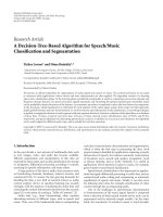
3.2.2. Models sheet
The main panel of the PETROMODELER, models
sheet, contains four columnar sections: (a) parameters
ERSOY / Turkish J Earth Sci
for bivariate and spider diagrams, (b) melting model
parameters, (c) crystallization and contamination model
parameters (Figure 3).
In the first section, the x- and y-axes of the bivariate
diagram are chosen using three combo-boxes for each axis
(such as Sr vs. Ba; Sr/Ba vs. SiO2, 87Sr/86Sr vs. La/Yb) (Figure
3a). The axes can also be set with linear or logarithmicscales. Below this section, the rock groups are chosen by
ticking on the related check-boxes in order to plot them
on the diagrams (Figure 3b). The names of the rock groups
automatically come from the samples sheet. The “Melt
Composition” combo-box allows the user to select any
melt composition, such as acidic, intermediate, or basic
for their partition coefficient data sets already entered
into the parameters sheet (Figure 3c). The “Normalizing
Factor” combo-box allows the user to select any chemical
compositions which will then be used as normalizing
values on the spider diagram (Figure 3c). These values
may be entered or changed on the parameters sheet. The
names of the normalizing values in the combo-box are
updated by the related table on the parameters sheet,
which can be changed by the user. The name of the selected
normalizing factor appears on the logarithmic y-axis of the
spider diagram. Below this, three combo-boxes are used
to choose any “F” values (melt fraction) for the melting,
crystallization and mixing model results (Figure 3d). The
model results for the chosen value of “F” are shown on the
spider diagram. The “F” value is also labelled on the spiderdiagram (Figure 4). The values in these combo-boxes may
be changed by using the related buttons on the second
and third columns on the models sheet (by changing the
melting degree and increment buttons).
In the second columnar section on the models sheet,
the melting parameters and models are set (Figures 3e–f).
First, a starting material composition is chosen from the
m
“Starting Composition ( C0 )” combo-box (Figure 3e).
The names in this combo-box are updated from related
table on the parameters sheet (source rock table), which
can be changed by the user. A check-box near the combobox is used to show the composition of the selected material
on the bivariate and spider diagrams. The selected material
is also labelled on both the bivariate and spider-diagrams
(Figure 4). The “Melting Facies (Mineral Modes)” combobox is used to set the mineral modes for the source and
melt (Figure 3e). The names in this combo-box are entered
into the “Mineral Modes” table on the parameters sheet,
which can be changed by the user. In the “Melting Degree”
section, two buttons are used to choose; (a) the degree of
melting for the first step (the melting curve starts from this
point on the bivariate diagram), and (b) the increment for
melting. For example if the first button is chosen as 1% and
the second as 2%, then the curve of any melting models are
drawn beginning from 1% with increments of 2%, and the
points on the curve represents 1%, 3%, 5% ….19% partial
melting (Figure 3e) (10 incremental points describe the
melting curve on the bivariate diagram which appear in
the “for melting” combo-box shown on Figure 3d).
The buttons for melting models are placed below this
section (Figures 3f). By ticking the related check-boxes,
the instantaneous (CI) or accumulated (CL) melt and
residual solid (CS) and total residue (CR) compositions
for batch, fractional and dynamic melting models (for
modal and non-modal models) can be shown on the
bivariate and spider diagrams. If a melting model is
m
selected, the name of C0 is labelled on both the bivariate
and spider diagrams (Figure 4). F is also labelled on the
spider diagram. The critical mass porosity for the dynamic
melting models (Ф) is also set by the related buttons.
Major element compositions for melting models are not
modelled by PETROMODELER. Isotopic ratios remain
constant during closed-system melting models.
In the third columnar section on the models sheet,
the crystallization and contamination parameters and
the models are set (Figures 3g–j). A starting material
composition is first chosen from the “Starting Composition
f
( C0 )” combo-box to crystallize or contaminate the melt.
C0f can be chosen from; (1) any samples which are
already entered into the samples sheet (by “choose from
samples” button), or (2) any melting models performed in
the second column on the sheet (by “choose from melting
results” button) (Figures 3g). If first button is selected, then
the sample numbers appear on a combo-box placed just
below the first button, and any sample can be set as starting
composition from this combo-box. If the second button
is selected, then the user should set the melting type and
melt fraction by using the four combo-boxes placed below
the button. A check-box in the “starting composition
f
( C0 )” label is used to show the composition of the
selected material on the bivariate and spider diagrams.
f
The name of the selected C0 is labelled on both the
bivariate and spider-diagrams if any crystallization and
contamination model is selected (Figure 4). Below the
f
“starting composition ( C0 )” section, the fractionating
mineral assemblage is set, by giving their percentage
(Figures 3h). The names of the minerals can be updated
from the parameters sheet. The increment percent for
the crystallization and contamination models is set by a
button (Figures 3i). 10 increments are set automatically,
beginning from F=100% and the end of the crystallization
is indicated below the button. For example if the first
button is chosen as 1% then the curve of any fractionation
models are drawn beginning from 100% with increments
of 1%, and the points on the curve represents 0%, 1%,
2%, 3% …. 9% crystallization (Figure 3e). 10 incremental
points describe the fractionation curves on the bivariate
diagram, which also appear in the “for FC/AFC” combo-
121
ERSOY / Turkish J Earth Sci
a
e
g
f
h
b
i
c
d
j
COLUMN-I
bivariate and spider
diagram parameters
COLUMN-II
melting parameters
COLUMN-III
crystallisation and
contamination parameters
Figure 3. Partial screenshots of models sheet of PETROMODELER: (a–d) diagram parameters, (e–f) melting parameters, (g–j)
crystallization and contamination parameters.
122
non-modal
dynamic melting
accumulated melt
PFC
C
AFC
m
C0
f
0.0255
0.0250
FC
ZC-IFC
f
0
0.0260
Ba / K
EC-IFC
Com= PM (Palme & O'Neill 2004)
F= 0.01 - 0.1
Φ= 0.011
0.0265
0.0270
0.0275
0.0280
ERSOY / Turkish J Earth Sci
non-modal dynamic
melting total residue
0.000
0.020
0.040
C0= Model Resul t
F= 1 - 0.55
Ca= Upper Continental Crust (T aylor & McLennan 1995)
r= 0.17
δ= 0.4
0.060
0.080
0.100
0.120
La / Sr
Figure 4. An example of bivariate diagram showing several differentiation trends for Ba/K vs La/Sr.
box shown on Figure 3d. F value for the spider diagram is
chosen from the related combo-boxes in the first column
on this sheet (Figure 3d). Any crystallization model can be
selected by ticking on the related check-boxes (Figure 3i).
The “δ” value for the EC-IFC and ZC-IFC can be set by a
button (Figure 3i).
Contamination models are constructed using either
the AFC or Mixing models. The assimilant material
composition for the AFC model (Ca) is chosen from a
combo-box and related check-box. The names in the list
of the “Assimilant” combo-box can be updated from the
parameters sheet, which can be changed by the user. The
“r” value for the AFC model is set by the related button
(Figure 3i). Another contamination process, mixing
model can be constructed by selecting the check-box. C1
f
is already selected from the “starting composition ( C0 )”
section, which is used for other crystallization processes
(Figure 3g). C2 is selected from the combo-box labelled as
“Mix with:” (Figure 3j). In this section, C2 can be chosen
from; (1) any samples which are already entered into the
samples sheet (by selecting “a sample”), or (2) any melting
models performed in the second column on the sheet
(by selecting “a model melt”) (Figures 3g). If “a sample”
is selected, then the sample numbers appear on a combobox placed just below the first button, and any sample
can be set as starting composition from this combo-box.
The last item of this list is the assimilant composition (Ca;
selected from AFC section), which can also be selected
as C2. If “a model melt” is selected, several melting results
appear in the related combo-boxes (Figures 3j). Hence,
mixing models between two samples or between a sample
and assimilant, or between a sample and a modelled melt
composition can be modelled.
3.2.3. Converter sheet
In this sheet the normative mineralogical compositions of
the samples entered into the tables in the samples sheet
are calculated. The normative mineralogical compositions
of a given sample are calculated on both a weight% and
volume% basis. The sample can be chosen from a combobox, for which the major element composition and group
name appear on a table. In this sheet, the oxide abundances
can also be converted to element abundances on basis of
wt% or ppm.
3.3.4. Numerical output sheet
In this sheet, the numerical outputs of the selected melting
or crystallization model are derived from two tables.
The results and parameters of the melting model appear
in the first table. Three combo-boxes are used to choose
the melting model. The relevant parameters appear in
the columns related to the selected melting model. A
similar table is constructed for the crystallization and
contamination processes.
4. Conclusions
PETROMODELER (Petrologic Modeler) is a Microsoft®
Excel© spreadsheet program which numerically and
graphically models magmatic processes, such as melting,
crystallization and mixing by using trace elements and
isotopic ratios. In the program, trace element compositions
of; (a) cumulated, and (b) instantaneous partial melts, and
(c) residual solid, and (d) total residue from melting of
any rock type can be calculated by using batch, dynamic
and fractional melting models. The composition of
these model melts (or any analyses of natural samples
entered into the program) can also be used as the starting
123
ERSOY / Turkish J Earth Sci
composition for; (a) perfect equilibrium crystallization,
(b) perfect fractional crystallization, (c) equilibrium
crystallization-imperfect fractional crystallization, (d)
zoned crystallization-imperfect fractional crystallization,
(e) combined assimilation and fractional crystallization,
and (f) mixing models.
All these models can be graphically shown on a
bivariate diagram, for which axes can be set as linearor log-scaled, or on a logarithmic multi-element spider
diagram. The diagrams can be exported as “gif ” files. The
numerical outputs of these models can also be exported
as tables.
Acknowledgment
This manuscript has been approved by valuable comments
of Samuele Agostini. Special thanks to Ercan ALDANMAZ,
Erdin BOZKURT and Mehmet KARACA for editorial
handling.
References
Anderson, A.T. & Greenland, L.P. 1969. Phosphorus fractionation
diagram as a quantitative indicator of crystallization
differentiation of basaltic liquids. Geochimica et Cosmochimica
Acta 33, 493–505.
DePaolo, D.J. 1981. A neodymium and strontium isotopic study
of the Mesozoic calc-alkaline granitic batholiths of the
Sierra Nevada and Peninsula Ranges, California. Journal of
Geophysical Research 86, 10470–10488.
Ersoy, Y. & Helvacı, C. 2010. FC-AFC-FCA and mixing modeler:
a Microsoft® Excel© spreadsheet program for modeling
geochemical differentiations of magma by crystal
fractionations, crustal assimilation and mixing. Computers and
Geosciences 36, 383-390.
Foley, S.F., Venturelli, G., Green, D.H. & Toscani, L. 1987. The
ultrapotassic rocks: characteristics, classification and
constraints for petrogenetic models. Earth Science Reviews 24,
81–134.
Gast, P.W., 1968. Trace element fractionation and the origin of
tholeiitic and alkalic magma types. Geochimica et Cosmochimica
Acta 32, 1057–1086.
Irvine, N. & Baragar, W.R.A. 1971. A guide to chemical classification
of the common volcanic rocks. Canadian Journal of Earth
Science 8, 523–548.
Keskin, M. 2002. FC-modeler: a Microsoft Excel spreadsheet
program for modeling Rayleigh fractionation vectors in closed
magmatic systems. Computers & Geosciences 28, 919–928.
®
©
Langmuir, C.H., Bender, J.F., Bence, A.E., Hanson, G.N. & Taylor,
S.R. 1977. Petrogenesis of basalts from the FAMOUS area
Mid-Atlantic Ridge. Earth and Planetary Science Letters 36,
133–156.
Le Bas, M.J., Le Maitre, R.W., Streckeisen, A. & Zanettin, B. 1986.
A chemical classification of volcanic rocks based on the total
alkali–silica diagram. Journal of Petrology 27, 745–750.
LeMaitre, R.W. 2002. Igneous rocks: a classification and glossary
of terms: recommendations of the International Union of
Geological Sciences, Subcommission on the Systematics of
Igneous Rocks, Cambridge University Press.
Maaløe, S. 1982. Geochemical aspects of permeability controlled
partial melting and fractional crystallization. Geochimica et
Cosmochimica Acta 46, 43–57.
124
McKenzie, D. 1985. 230Th-238U disequilibrium and the melting
processes beneath ridge axes. Earth and Planetary Science
Letters 72, 149–1 57.
Navon, O. & Stolper, E. 1987. Geochemical consequences of melt
percolation: The upper mantle as a chromatographic column.
Journal of Geology 95, 285–307.
Nishimura K. 2006. Numerical modeling of trace element behavior
during crystal settling and reequilibration in high-silica
magma bodies. Journal of Geophysical Researches 111, B08201.
Nishimura K. 2009. A trace-element geochemical model for
imperfect fractional crystallization associated with the
development of crystal zoning. Geochimica et Cosmochimica
Acta 73, 2142–2149.
O’hara M.J. 1993. Trace element geochemical effects of imperfect
crystal–liquid separation. In: Prichard, H.M., Alabaster,
T., Harris, N.B.W. & Neary, C.R. (eds), Magmatic Processes
and Plate Tectonics. Geological Society, London, Special
Publication, Insert number, 39–59.
O’hara, M.J. 1995. Imperfect melting separation, finite increment
size and source region flow during fractional melting and
the generation of reversed or subdued discrimination of
incompatible trace elements. Chemical Geology 121, 27–50.
Ozawa, K. & Shimizu, N. 1995. Open-system melting in the upper
mantle: Constraints from the Hayachine-Miyamori ophiolite,
northeastern Japan. Journal of Geophysical Researches 100,
22315–22335.
Ozawa, K. 2001. Mass balance equations for open magmatic systems:
Trace element behavior and its application to open system
melting in the upper mantle. Journal of Geophysical Researches
106, 13407–13434.
Peccerillo, A. & Taylor, S.R. 1976. Geochemistry of Eocene calcalkaline volcanic rocks from the Kastamonu area. Northern
Turkey. Contributions to Mineralogy and Petrology 58, 63–81.
Petrelli, M., Poli, G., Perugini, D. & Peccerillo, A. 2005. Petrograph: a
new software to visualize. model, and present geochemical data
in igneous petrology. Geochemistry, Geophysics, Geosystems 6,
Q07011.
Powell, R. 1984. Inversion of the assimilation and fractional
crystallization (AFC) equations; characterization of
contaminants from isotope and trace element relationships in
volcanic suites. Journal of the Geological Society 141, 447–452.
ERSOY / Turkish J Earth Sci
Rayleigh, J.W.S. 1896. Theoretical considerations respecting the
separation of gases by diffusion and similar processes.
Philosophical Magazine 42, 77–107.
Schilling, J.G. & Winchester, J.W. 1967. Rare-earth fractionation
and magmatic processes in Mantles of Earth and Terrestrial
Planets, edited by S.K. Runcorn, pp. 267–283, Wiley Intersci.,
New York.
Shaw, D.M. 2000. Continuous (dynamic) melting theory revisited.
Canadian Mineralogist 38, 1041–1063.
Wood, D.A. 1979. Dynamic partial melting: Its application to the
petrogenesis of basalts erupted in Iceland, the Faeroe Islands,
the Isle of Skye (Scotland) and the Troodos Massif (Cyprus),
Geochimica et Cosmochimica Acta 43, 1031–1046,
Zou, H.B. 1998. Trace element fractionation during modal and
non-modal dynamic melting and open-system melting: A
mathematical treatment. Geochimica et Cosmochimica Acta 62,
1937–1945.
Zou, H.B. 2007. Quantitative Geochemistry. London, UK. ISBN:
9781860946462.
125