Doctoral thesis summary: Research proposed design mothod and construction to improve the quality of small drainage works on the road inLao People''s Democratic Republic
Bạn đang xem bản rút gọn của tài liệu. Xem và tải ngay bản đầy đủ của tài liệu tại đây (505.5 KB, 24 trang )
1
INSTRODUCTION
1. Reason of research selecting
Lao People’s Democratic Republic is on the way of
modernization. The road networks is being renovated, upgraded and
construction to serve the development needed of the country. In
recent years, Lao Party and the State attach importance to the
construction of infrastructure. Which they have focused on
constructing and developing road network, especially roads.
When constructing road, we have special attention on small
drainage works across it, although it is not large proportion
compared with others, but the possibility of flood drainage of small
drainage works and influence are directly related to the life of the
pavement, roadbed and other structures on the road.
Laos is located in the tropical monsoon climate, rainfall and
climate conditioning in the year, but some areas have large and
irregular rainfall. Laos has hilly terrain with high cliffs and network
traffic from north to south through the mountainous route, because of
high slope, the volume of water flow on the peak of the mountain
flow down quickly lead to damage the samall drainage works and
make the quality of roads is not stable over the seasons. One of the
important reasons is the method of hydraulic calculation for small
drainage works and a large selection of the dangerous state of the the
road construction is irrational. To improve drainage capability across
roads need to study some hydraulic computational problems such as:
hydraulic calculation of water level and water slopes, estimating
hydraulic of step cascade and steep slope, scour at culvert outlets and
calculated velocity of soil scouring at culvert outlets. All these issues
that involve to the research methods to designed and increase
possibility of flood drainage for small drainage works.
2
In Laos, do not have the design method of hydraulic
calculations of drainage works yet, we currently use foreign methods
such as (Europe, America, Vietnam) for natural environment
conditions and climate in Laos.
In fact we need further research on this issue. With
qualification and experience of the scientists Vietnamese
techniques can help me a lot on my research. So that, Government
Lao send me to research this topic: “Research proposed design
mothod and construction to improve the quality of small drainage
works on the road in Lao People's Democratic Republic”.
2. Purpose of the research
The thesis is focused on hydraulic calculation of small
drainage works across of road such as: (step cascades, steep slope,
velocity of soil scouring at culvert outlets and scour at culvert
outlets). So that, Proposed solutions and selection methods to
reinforced or choose the mitigating energy method relevant with
downstream culverts on the roads. And find solutions for small
drainage works across the road with terrain characteristics matching
the natural environment conditions and climate in Laos.
3. scope of the reseach
The scope of the research is the calculate the hydraulic for
small drainage works across the road in Laos.
4.
Research Methodology
5.
Research methodology combines empirical theory.
Structure of the thesis
Thesis presented in 166 pages and 04 chapters,
Conclusions, Recommendations subsequent research, References
and Appendixs.
3
CHAPTER 1: OVERVIEW THE CHARACTERISTICS
NATURAL CONDITIONS, ROAD NETWORKS AND THE
DESTRUCTION OF SMALL DRAINAGE SYSTEMS ON THE
ROAD IN LAO P.D.R
1.1.
Features of terrain conditions and climate in Laos
Lao People’s Democratic Republic is a country with
relatively area of 236,800 km2. The terrain of Laos mainly rolling
terrain with 70% and 30% of flat terrain.
Topography: mountains and highlands make over 3/4 of the
natural area, the rest are flat terrain. Generally the mountains in Laos
with an average elevation on the north and east, the highest peak is
Mount Bịa (2820m), and some other high peaks such as Mount Xao
(2690m), Hunting mountain (2218m) mountain Huat (2452m).
Mountain in Northeast Provinces Xieng Khouang Laos Tattooing
Nua, which begins north of the Truong Son mountain range. Their
general direction is northeast southwest lies the entire West, not
consecutive long and flat as in Mekong Delta.
Climate: tropical monsoon climate, with two seasons:
+ Rainy season: starting from May to November, The temperature is
about 30oC, rain fall quite often, and there are some flooded overflow
the Mekong river after several years.
+ Dry season: from November to April, less rain and temperature is
about 15oC, Mountains sometime is 0°C.
1.2. Introduction of the road network systems in Laos
1.2.1. Period before 1975
1.2.2. Period 19751985
1.2.3. Period 19852000
1.2.4. Period 20002015
4
In Laos there is not yet have a complete road network systems
to connecting between provinces and districts. The Internal transport
to some provinces still cannot let the car drive smoothly to the
provincial capital, and between districts, and to the villages are more
difficult. Now, the road network systems in Laos is only have grade
III, IV and V.
1.3. Depravity of small drainage works on the roads in Lao
P.D.R
Laos has the tropical monsoon climate, cause of rainfall and
climate in year, mainly some areas with lots of rain and some areas
with irregular rainfall over the year. Laos has hilly terrain with high
cliffs and road network systems from north to south through the
mountainous route, due to the high slopes, volume of water on the
peak of the mountain flow down quickly, resulting to damaged
drainage system on roads and makes the quality is not stable over the
seasons.
Drainage systems on the roads in Laos have designed with low
technical, and need maintenance infrequently, with the management
and maintenance fee are limited, so it may not yet maintenance in
time for roads in Laos.
1.3.1. Common failures of drainage systems on the roads and cause
of failures
Phenomenon damaged small drainage works on the roads in
Lao P.D.R occurred on all the routes are exploited. Consequently, as
they so often cause large losses, costs, repair. To serve thesis
explored many roads and servey in Lao P.D.R: road No.1D, 1J, 2E,
4A, 7, 8, 12...The survey results were presented detailed in thematic
reports: The destructive small drainage works on roads in Lao
People's Democratic Republic and the cause. In here summarize
5
some typical damages directly related to the issues in the content of
the thesis.
1. Damaged drains (hình 1.2A và 1.2B);
2. Damage upstream and downstream of culvert (hình 1.3A,
13B, 13C và 13D);
3. Damage erosion of culvert body (hình 1.4);
4. Damaged joints of culvert (hình 1.5);
5. Deposition soil, sand in culvert (hình 1.6A và 1.6B).
1.3.2. The situation applies structural drainage works in Laos
During the construction and development of transportation
network systems, we research for shapes of culverts structures and
small bridges on the roads, and also make new research to improve
the quality of construction, easy to maintenances, lower fee, and
ensuring the quality and safety for cars driving on the mountain
roads.
Generally these small drainage structures (culverts and small
bridges) have been applied on the roads in Laos, such as: reinforced
concrete pipe culvert, reinforced concrete box culverts, steel culverts,
ditch on 2 side of roads, reinforced concrete bridge etc...
Currently, we not yet have research and technical solutions
to handle the drainage structures in Laos. When the damaged roads
sections occur, we will have organization to repairs, and choose a
certain solutions suitable to the actual damages and depending on the
professional competencies and experience of construction unit.
1.4. Conclusion chapter 1
After studying, the researcher have some necessary problem
and some important conclusions below related the objectives of the
thesis:
6
1. Develop and maintain road network systems to serve the
develop economy of Laos, the Lao Party and State were identified as
a key task, lots of roads will be built and renovated in future. For the
construction road works effectively need to improve the quality of
construction. Tasks to improve quality of road construction should
start at the planning stage to design. This thesis wants to participate
in the first stage above with the aim of improving the quality of
construction to extend the level service life of the project and ensure
the quality.
2. Together with colleagues, the researcher have reviewed
some main roads systems as mentioned above with a very common
failure on the destructive road at positions of drainage structures like
small bridges and culverts. Depending on varied of destructive forms
but the most common failures are roadbed, pavements at the
location of erosion, scour at the culvert outlets. This destructive
pattern is absolutely cause of forecast hydrological work and
hydraulic modeling calculation are not suitable, resulting the water
speed, water pressure on the pavement is too strong that can damage
road construction and reduced security of safety traffic.
These predictions explain the thesis that focused on hydraulic
calculation for small drainage systems. Thus, hope that later road less
swept away by water, less culverts damage, and less bridges damage
after flood season. This destructive pattern is different from bridges
collapsed or culverts failures under the impact of vehicle weight and
embankment weight itself. These types of failures are caused by poor
construction quality, this thesis does not solve that problem.
3. Climatic conditions, temperature, rain and wind are very
harsh. Later when applying the general formula for hydraulic
7
calculation for small drainage systems across the road needed
attention to this characteristic. But this is a very complex problem
requires more research, and more construction experience. So my
thesis wanted to have the general granted theory and experience of
scientists, technicians to achieved with desire problems are resolved
more quickly.
To response the objectives and contents of the thesis, the
following issues will be studied in the next chapter:
a. The main contents of hydraulic calculation of pooled step
cascade, hydraulic resistance at steep slope, scouring of the
downstream river bed and scour at culvert outlets of small drainage
works across the road;
b. Research proposed design method of hydraulic calculation
for small drainage structures across the roads in Lao People’s
Democratic Republic.
c. Construction solution for small drainage works across
specific terrain in Lao People’s Democratic Republic.
CHAPTER 2: OVERVIEW OF HYDRAULIC PROPERTIES
WITH POOLED STEP CASCADES, HYDRAULIC
RESISTANCE AT STEEP SLOP SCOURING OF THE
DOWNSTREAM RIVER BED AND SCOUR AT CULVERT
OUTLETS OF SMALL DRAINAGE WORKS ACROSS THE
ROAD
2.1. Overview of hydraulic properties with pooled step cascades
in hydraulic type stilling basin
2.1.1. The studies hydraulic property of pooled step cascades
Pooled step cascades were studied by lots of authors with
different approach like: Velocity coefficient for rectangular cross
8
sections of the water layer of (Alekxeev IU.S, 1965), the forms of
flow current through the step cascades of (IU.M Konstantinov, 1966,
1969), the speed and depth of flow on upstream of (Popov VN,
1957)...
Pooled step cascades include many step cascades link
together in serial with cascade types are applied for the rolling
terrain, to reduce volume of earthworks, less environmental
destruction. Thus, each step cascade must be calculated for the
minimum length of hydraulic properties, while ensuring the specific
terrain conditions that is the average local slope must be satisfied:
Scb=∑Pi/∑Li [5].
When calculate pooled step cascades, we often only
calculate first cascade and second cascade, the next cascade is
calculated as second cascade, the last cascade we calculate include
the influence of water current on downstream flow, usually in
hydraulic type stilling basin.
2.1.2. The formulas for hydraulic pooled step cascades in basin
type
2.1.2.1. Determine the length of the water fall in the step cascade
inlets [5]
Length of water fall in the rectangular channel can be
calculated by the formula [5].
2.1.2.2. Length of water fall along the water current at stepped weir
[5]
Water current flow on stepped weir when the cascades are
not flooded include two parts are the free fall part in the air and
nother submerged on stepped weir can be determined according the
research of (Kostantinov IU.M, 1988) [80].
9
For the rectangular section:
Pavlovski N.N
(2.9)
Chertouxov M.D (trung bình)
(2.10)
or
(2.10a)
Bradley and Peterka (2.11)
Ohtsu et al
(2.12)
2.1.2.3. Experimental study on the inlet cascades hydraulic jump [5]
Figures measure pressure changes along the depth at inlets,
according to research (Rajaratnam and Muralidha, 1968) [54]. Excess
pressure at the top and bottom water flow is zero, in the scope which
value of curvature is greater than atmospheric pressure, but always
less than the statically hydrostatic pressure.
Research and semi experimental indicated h b / hc = 0715 for
rectangular sections.
2.1.2.4. Determine the depth on narrowing sectional [2], [5]
Depth on narrowing sectional on stepped weir determined by
the equation of (Bernoulli) for the cross upstream channel and
narrowed section on stepped weir for rectangular sections.
Eo=hch+(q2/2g 2h2ch)
(2.14)
1). Research of (Agroskin I.I, 1964) [2], [5]:
q= hch(2g(Eohch))0.5
For: ch=hch/Eo and
2ch
(2.18)
=h2ch/Eo
F( ch)=q/( E3/2o)
(2.19)
Through the relations of function F( ch)=q/( E3/2o)
corresponding to the coefficients ratio value of different speed
(Appendix 1) we can calculate and corresponding coefficients
ratio .
2). Research of (Rakhamanov A.N) [5]:
10
Using equation (2.14) write the equation in the form of ratio
relative to the critical depth :
Eo/hc=(hch/hc)+(1/2 2)(hc/hch)3
For:
Eo
=Eo/hc;
ch
=hch/hc and
2ch
(2.20)
=h2ch/hc
Relationship curve between , with corresponding
coefficients ratio (Appendix 2).
2.1.2.5. Calculated depth of stilling basin [5]
Determine depth of stilling basin can follow the diagrams of
(Chertouxov M.D, 1962) that diagrams have built through relations
between z=f(
, ) (Appendix 3).
Eo
The graph shows the value d corresponding to the hydraulic
jump in place determined by the formula (2.32) as follows:
d=
h Eo
Eo c
(2.32)
Research of (Detlef Aigner) [23]:
Calculated the pooled step cascades at hydraulic type stilling
basin [23] by known flow unit and step cascade height can find
tg =P/L, after that find the relation between p t/P with hc/P and can
calculate the size of pooled step cascade such as: height of stilling
wall, length of step cascade ...
2.1.3. Evaluation of hydraulic type stilling basin
This study, authors focused on solving equations to find
depth of narrow section on the stepped weir, large combines depth of
hydraulic jump with the depth of narrow section on stepped weir is,
calculate wall height of pooled step cascade and depth of stilling
basin on final cascade follow the analysis method and numerical
method, charting to define the relationship between p t/hc with P/hc
and Lbc/hc with P/hc define pt and Lbc.
2.2. Overview of research on hydraulic resistance at steep slope
11
2.2.1. The studies related to hydraulic resistance at steep slope [5]
Calculated hydraulic at steep slope, are divided into three
sections: culvert inlets, steep slope and culvert outlets sections
(Figure 2.7).
2.2.1.1. Calculate culvert inlets hydraulic at stepped chutes
bb=Q/(m(2g)0.5(Ho3/2))
(2.40)
2.2.1.2. Calculate steeped slopes hydraulic
Slopes length:
Ld=(P2+L2)0.5
(2.41)
Slopes of water slopes:
id=P/Ld
(2.42)
Flow modulus of channel:
Ko=Q/(id)
0.5
(2.43)
2.2.1.3. Calculate culvert outlets hydraulic at steep slope
h2=(h21+2h3c(1/h11/hcr))0.5
(2.44)
2.2.2. The issue of hydraulic resistance calculation of steep slope
To determine the flow ability of drainage structures across
the road such as culverts, steep slope, step cascades are also
important to determine the correct average speed of water current
and correspondent of flow volume, speed and volume of water
current depends on defining resistance friction coefficient f , (Darcy
Weisbach) [79].
1). Research of (Pavlovski N.N) [79]:
Define Sedi factor used for 0.1
(2.49)
Exponent
In fact, sometimes calculate with values y in constant, often
taking y=1/6.
2). Research of (Aivazian, 1977, 1984, 1985, 1987, 1992,
1996, 2001) [73], [74], [75], [76], [77]
f=a+bixRy
(2.51)
12
Analysis results for calculating the coefficient f in concrete
bed (Kosichenko IU.M, 08/1993) [81]:
a) For uniform flow (Fr<1):
fe=0.245/Re0.158
(2.52)
b) For tumbling flow (Fr>1):
fx=0.0187Re0.0384
(2.53)
2.2.3. The Issues should be studied
This research focused on analysis of f coefficient in concrete
bed through the use of real data [73], [74], [75], [76], [77], in
(appendix 5) [89].
2.3. Overview of oil scouring at bottom of flow current
2.3.1. The gained issue
Now, have 4 research ways of startup soil scouring:
1. Velocity of soil scouring, which puts relations between
soil diameter d and velocity of soil scouring or medium
velocity at bottom of flow current to make the soil elements
moved.
2. Lift force, which lift the soil elements excess of itself
weight of the soil in water current.
3. Critical stress, which is based on the perception of
tangential force applied to the soil elements at the bottom of
the flow current, is the main cause the soil elements moved.
4. Probability method is applied to solve problems.
2.3.1.1. Velocity of soil elements
2.3.1.2. Perceptions about lift force impact on soil elements Py
2.3.1.3. Tangential stress of flow current
2.3.1.4. Probability method
2.3.2. Reviews
13
In this study, the authors want to show out a simple model for
uniform sand elements are impact with hydrodynamic forces and
move by sliding along the flow, account to the turbulent regime and
pulsating flow velocity under law of and using the results of recent
studies.
2.4. Overview of researches on scour at culvert outlets on small
drainage works across the road
2.4.1. Studies concerning the scour at culvert outlets and scour at
small bridge
Research of (Andreev O.V, 1963):
(2.74)
2.4.2. The issue should be studied
Authors studied the issue using equation for momentum change to
settle the theoretical calculation formula for scour at culvert outlets,
small bridges to compare and check the results of experiments over.
2.5. Conclusion Chapter 2
Chapter 2 has overview of research on the pooled step
cascades, hydraulic resistance on the steep slope, scouring of the
downstream river bed and scour at culvert outlets of small drainage
structures across the road, research to choose the formula for
hydraulic calculation of small drainage works across the road.
CHAPTER 3: RESEARCH PROPOSED DESIGN METHOD
AND CONSTRUCTED TO IMPROVE THE QUALITY OF
SMALL DRAINAGE WORKS ON ROADS IN LAO PEOPLE’S
DEMOCRATIC REPUBLIC
3.1. Theoretical hydraulic calculation for drainage works across
the road
14
As described in Chapter 2 we have the following theory to
calculate hydraulic for small drainage structures across the road:
3.1.1. Calculate pooled step cascades
3.3.1.1. Determining the depth of pooled step cascades
(3.1)
3.1.1.2. Determining the narrowing length of stepped weir
Write the Bernoulli equation through two sections (11) and
(cc) Compare section and write equation like (Figure 3.3).
(3.2)
3.1.1.3. Calculated the height of stilling wall of stepped chutes
pt= h2chH1
(3.8)
3.1.1.4. Combined stilling basin
To have hydraulic jump submerged in basin (Figure 3.5),
stilling basin depth should add from 5% to 10% (), we have:
(3.11)
3.1.1.5. Cac b
́ ươc chi tiêt tinh bâc n
́
́ ́
̣ ước nhiêu câp dang bê tiêu năng
̀ ́ ̣
̉
3.1.2. Steep slope
Hydraulic Calculations of steep slope as outlined in Chapter 2. So
hydraulic resistance coefficient can be in general form, for a specific
type in steady flow regime using dimensional equation, we have:
(3.15)
where:
gravitational constant;
absolute roughness;
hydraulic radius
reynolds number
froude number
15
3.1.3.
Scour at culvert outlets
3.1.3. Scour at culvert outlets
3.1.3.1. Determine velocity of scouring of downstream river bed
3.1.3.2. Momentum equation of steady flow
3.2. Research drawing chart to determine pooled step cascades
and resistance in steep slope
3.2.1. Hydraulic calculation of pooled step cascades in rectangular
cross section at hydraulic type stilling basin
3.2.1.1. Calculation steps for pooled step cascades by Excel
3.2.1.2. Solving step cascades calculated by Excel
Hydraulic calculation for pooled step cascades with
discharge per unit width of the crest overfall is when step cascades
height are , slopes between upstream and downstream is and .
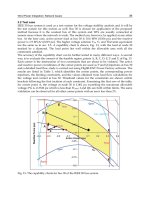
3.2.1.3. Bluding diagram to calculate the pooled step cascades by
relation between discharge per unit width of the crest overfall and
step cascades height on excel program (Figure3.15)
Hình: 3.15
(3.24)
(3.25)
3.2.2. Calculate hydraulic steep slope
16
3.2.2.1. Building the relation experimental of hydraulic resistance f
To see more clearly the change of resistance coefficient
between tumbling flow and uniform flow, the author uses the actual
data (table PL5.1, appendix 5) [89] and build relations between the f
and Re as (Figure 3.16 and Figure 3.19 ).
Figure 3.16
Figure 3.19
3.2.2.2. Conclusion Building the relation experimental of hydraulic
resistance f
For trapezoidal section:
fHTH=0.0182Re0.0381
(3.26a)
For rectangular section:
fCN=0.00045Re0.3123
(3.26b)
3.3. Research velocity of scouring of the downstream riverbed
and scour at the culvert outlet for drainage structures across the
road with for cohesionless soil
17
3.3.1. Calculate velocity of scouring on the downstream river bed
and average velocity for flow current on cohesionless soil
3.3.1.1. Build equation [6], [7], [8], [87]
(3.35)
3.3.1.2. The result of the velocity scouring of downstream reverbed
Velocity scouring of downstream reverbed, equation (3.35)
was compared with formulations of Goncharov and [6] for the soil
dimensions (table 3.6).
Table 3.6. The result of velocity with no scouring of
downstream reverbed
Author
Goncharov
[6]
1
0.140
0.136
0.20
2.5
0.222
0.215
0.25
5
0.313
0.304
0.35
10
0.443
0.430
0.50
15
0.543
0.527
0.60
25
0.701
0.680
0.80
40
0.886
0.860
1.00
75
1.213
1.180
1.35
3.3.2. Estimating scour at culvert outlets of drainage works across
on road
3.3.2.1. Scour culvert outlets at downstream for momentum equations
of uniform flow [7]
For culvert under the road, if there is not enough
reinforcement length, erosion scour hole will occurred and flow
structure is shown in (Figure 3.21).
18
(3.55)
3.3.2.2. Scour culvert outlets at downstream for Federal Highway
Administration (FHWA) [7], [86], [88]
(3.58)
where:
depth of scour (m);
width of scour (m);
length of scour (m);
volume of scour (m);
hydraulic radius at the end of the culvert
(assuming full flow)
discharge ;
acceleration of gravity 9,81 ;
thời gian lũ (phút);
material standard deviation;
, và are coefficients (bảng 3.7);
drop height adjustment coefficient (bảng 3.8)
slope correction coefficient (bảng 3.9);
3.3.2.3. Scour culvert outlets at downstream for HY8 software [85]
HY8 is a Window interactive program with a DOS engine
that allows the user to :
Design and analyze a culvert or a system of culvert.
Consider and analyze roadway overtopping.
Generate and route hydrographs through a culvert.
Design and analyze energy dissipators.
3.3.3. Apply formula for calculate Scour culvert outlets for small
drainage structures across on road.
19
3.3.3.1. Introduction of the regional natural conditions routes
Through the current state of construction and analysis on
failure cause to ensure drainages are stable, the author will offer
method to repair the downstream culvert outlets by calculating
erosion method of (Andreev OV), equation (2.74) and momentum
equations for uniform flow [7] and check with HY8 software [85].
3.3.3.2. Research results achieved
Table 3.10. The result of calculate scour culvert outlets with HY8
software at two culverts placement (Appendix 10 and Appendix 11)
Station
km 0+934.43
km 5+500.00
Diameter
D (m)
1.00
1.50
Scour hole Dimensions
Depth
Width
Length
hx (m)
Bx (m)
Lx (m)
0.961
5.345
4.607
2.194
13.076
10.723
Volume
(m)
17.713
193.817
Table 3.11. The result of calculate scour culvert outlets with Federal
Highway Administration (FHWA) at two culverts placement (Appendix 12
Station
km 0+934.43
km 5+500.00
and Appendix 13)
Scour hole Dimensions
Diameter
Depth
Width
Length
D (m)
hx (m)
Bx (m)
Lx (m)
1.00
0.792
3.808
6.007
1.50
1.798
10.358
13.238
Volume
(m)
12.427
144.122
Table 3.12: Summary results for depth of scour
Calculation method
Depth of scour
Depth of scour
km 0+934.43
km 5+500.00
Reinforced, equation (2.74)
0.49 (m)
1.63 (m)
Not reinforced, equation (2.74)
0.98 (m)
2.82 (m)
Momentum equations [7] (Appendix
0.76 (m)
1.51 (m)
15 and Appendix 16)
HY8 software [85] (Appendix 10
0.961 (m)
2.194 (m)
and Appendix 11)
Federal Highway Administration
0.792 (m)
1.798 (m)
(FHWA) [7], [86], [88] (Appendix
12 and Appendix 13)
20
3.4. Conclusion Chapter 3
After studying and analyzing specific calculations above, it
is possible to apply the formula to calculate for small drainage
structures in Laos. When we use it, we needs to pay attention on the
limitations of each method described in the comment section and
conclusions.
CHAPTER 4: CONSTRUCTION SOLUTIONS FOR SMALL
DRAINAGE WORKS ON THE ROAD WITH SPECIFIC
TERRAIN IN LAO PEOPLE’S DEMOCRATIC REPUBLIC
4.1. Hydrographic surveys and can be applied to design drainage
works in Lao P.D.R
4.1.1. Content hydrographic survey work to design drainage
systems
4.1.2. The hydrological calculation methods can be applied to
design small drainage system in Laos
4.1.2.1. Methods for determination of water flow in Laos
(4.1)
where:
Q Peak discharge, m 3 / s ;
I rainfall intensity, mm / h ;
2
A drainage area, km ;
C rational method runoff coefficient, (bảng 4.1).
4.1.2.2. Methods for determination of water flow of Design Institute
of Transport Science and Technology in Vietnam [1], [9]
where:
(4.4)
Q P design flow at frequency P%;
H P calculated daily rainfall at the frequency P%,
21
flow coefficient with regard to the amount of
lost rain water, daily rainfall H P and catchment area
F;
AP relative flood peak flow module at the
frequency
factor with regard to effects of ponds, lakes, and
swamps (table 4.2);
F catchment area, km2;
4.1.2.3. Methods for determination of water flow of Prof. Ph.D of
Science. Nguyen Xuan Truc [9]
(4.11)
flow reduction coefficient depending on the
basin area (table 4.5);
ap
calculated rainfall intensity, mm/ph.
where:
4.2. Solutions for pavement drainage and cross drainage
4.2.1. General principles
4.2.2. Pavement surface drainage and drainage across the road
4.2.2.1. Selection of steep slope
4.2.2.2. Selection of pooled step cascade
4.2.2.3. Selection of drainage structures
4.3.3. Strengthen method for upstream structures
When designing to drain water into the slope we need to
take notice:
1. To make the water flow into the drain smoothly. If the
stream is too crooked, we must handle the flow and warranty with
no sinuous flow, not shorten the inlets structures.
2. The length of flume section need to excavate to irrigation
streams of water into the drain as short as possible. If the geology of
22
the flume on upstream is porous soil type, we are not recommended
to excavate the flume to avoid the water stream damage roadbed.
3. If the culvert is located on bedrock, based on terrain
conditions to handles entrance. Slope in cutting section at upstream
usually take from 1.0: 1.0 or 1.0: 2.0.
4. When the flume at upstream are small gravel stone, they
must built a small retaining wall to protect the slices segment at the
culvert outlets.
4.3.4. Strengthen method for downstream structures
4.3.4.1. Some cause to result downstream structures failures
4.3.4.2. Handling method to against erosion on downstream
structures
CONCLUSIONS AND RECOMMENDATIONS
On the basis of the research results presented in Chapters 1,
2, 3, 4, we have some conclusions and propose below:
I. REVIEW OF CONTRIBUTIONS TO THE DEVELOPMENT
OF SCIENCE AND PRACTICE OF THE THESIS
Thesis has made a small contribution to the development and
practice below:
1). Failure of drainage systems on the roads in Laos, is common
phenomenon failure of the road, presented in chapter 1. Damage of
small drainage structures are very serious to impact the traffic and
causing economic losses. To Improving the quality of service ability
of small drainage works on road is a real demand and have great
significance for economic and technical assistance to the Lao. To
process to build high quality road, to make the economic
development for country.
23
2). To improve the service ability of the drainage works on roads,
need to improve the basic construction design: construction and
inspection of the construction process, damage failures survey of
small drainage systems presented in Chapter 1. We found that, the
main reason causing damage are the selected structures is not the
right structures type, right spans. These causes occur during the
design process was no survey methods for flow current, for select the
location of structures, for selected hydraulic calculation methods for
the particular type of structures.
3). In terms of hydraulic, The research focused on hydraulic
calculation methods for common projects and should use hydraulic
type stilling basin widely in Laos.
4). When hydraulic calculations of pooled step cascades the
variability data of water flows with different height step, we can
build chart to determine pooled step cascades, equation:
(3.24)
(3.25)
5). Research hydraulic resistance steep slope, the research results
indicate, equation:
For trapezoidal section:
fHTH=0.0182Re0.0381
(3.26a)
For rectangular section:
fCN=0.00045Re0.3123
(3.26b)
6). Research velocity of scouring on the downstream river bed,
equation:
(3.35)
24
7). In terms of hydrology as presented in Chapter 4, we see that in
Laos should choose hydrological calculation method such as rainfall
intensity method of Laos and (22 TCN 22095) Vietnam. Then select
the highest flow values to design.
8). The types of structures and their structural detail in chapter 4, we
recommend using with the purpose of improving the service quality
of the drainage systems in Laos.
9). For better serve to product and scientific development, we should
draw relative length charts of stepped weir and relative wall height to
find the wall height and length of the stepped weir, allowing the
designer can use, consult and compare the results with other
formulations for use in the design process in Laos.
10). Survey checks, using HY8 software to calculate depth of scour
in the different geological conditions. Ensure for quick calculation
and reliable results on erosion such as: width of scour bx, length of
scour Lx and volume of scour . Help to strengthen downstream
accurately, saving fee, and also can predict fairly accurately the
actual operational status of structures.
II. NEXT RESEARCH PLANS
Study in essence, cause erosion on downstream culverts and
small bridges on roads. Based on the experimental data with multi
case, then use the mathematical method to calculate the different data
in different structures.