Ebook ABC of practical procedures: Part 2
Bạn đang xem bản rút gọn của tài liệu. Xem và tải ngay bản đầy đủ của tài liệu tại đây (7.43 MB, 78 trang )
CHAPTER 12
Access: Emergency – Intraosseous
Access and Venous Cutdown
Matt Boylan
Midlands Air Ambulance, DCAE Cosford, UK
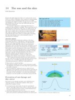
Poor technique
e.g. Infrequent user
OVER VI EW
By the end of this chapter you should be able to:
• understand the indications for intraosseous access and venous
cutdown
• identify the sites used for intraosseous access and venous
cutdown
Venous shutdown
e.g. shock, cold
Vein damage
e.g. IV drug abuse
Difficult
intravenous
access
Entrapment
e.g. limited access
Extremes of age
e.g. elderly, infants
• be aware of different types of intraosseous access devices
• describe the procedure of performing intraosseous access and
venous cutdown
Limb injuries
e.g. amputations
• understand the contraindications for intraosseous access and
PPE
e.g. CBRN
Environment
e.g. low light
venous cutdown.
Figure 12.1 Difficult intravenous access.
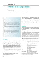
Compact
bone
Introduction
Gaining access to the circulatory system in the critically ill or injured
patient is an essential part of the resuscitative process. Failure to do
so can result in significant delays in the delivery of life-saving treatment. There are situations where peripheral intravenous access may
be difficult or even impossible (Figure 12.1). Intraosseous access
and venous cutdown are useful alternatives in this situation.
Where possible a full explanation of the proceedure should be
given to the patient and informed consent gained. However, in
many cases this will not be possible.
Osteon
Trabeculae
Periosteum
Haversian or
central canal
Intraosseous access
The intraosseous (IO) space consists of spongy cancellous
epiphyseal bone and the diaphyseal medullary cavity. It houses a
vast non-collapsible venous plexus that communicates with the
arteries and veins of the systemic circulation via small channels
in the surrounding compact cortical bone (Figure 12.2). Drugs or
fluids administered into the intraosseous space via a needle or
catheter will pass rapidly into the systemic circulation at a rate
comparable with central or peripheral venous access. Any drug,
fluid or blood product that can be given intravenously can be given
via the intraosseous route.
ABC of Practical Procedures. Edited by T. Nutbeam and R. Daniels. © 2010
Blackwell Publishing, ISBN: 978-1-4051-8595-0.
Volkmann
canal
Figure 12.2 Osseous blood supply.
57
58
ABC of Practical Procedures
Box 12.1 Contraindications to insertion of IO needle
• Proximal ipsilateral fracture
• Previous IO attempts in same bone
• Previous surgery at insertion site (e.g. sternotomy/knee
•
•
•
•
replacement)
Osteogenesis imperfecta (relative)
Osteoporosis (relative)
Overlying infection (relative)
Inability to identify landmarks (e.g. obesity)
Humerus
Sternum
A marrow sample aspirated immediately following needle
insertion can be used for biochemical (acid–base status, glucose,
electrolytes) and/or haematological (haemoglobin, cross-match)
testing. Test accuracy reduces following continuous infusion, drug
administration and prolonged cardiac arrest.
Insertion pain due to stimulation of nociceptors in the skin
and periosteum is equivalent to that of wide-bore peripheral
intravenous access. Pain on initial infusion is due to intraosseous
vessel wall distension and may be severe. It can be reduced in the
conscious patient by the administration of 20–40 mg lidocaine
(0.5 mg/kg paediatric) through the device before commencing
an infusion.
Pelvis
Insertion site selection
The factors affecting IO insertion site selection include the type
of device being used, the age/size of the patient, the presence or
absence of contraindications to insertion (Box 12.1), and the skill
of the operator.
Insertion sites
See Figure 12.3.
Sternum (manubrium)
One fingerbreadth (1.5 cm) below sternal notch in midline (adult).
Sternal devices only.
Humerus (greater tubercle)
Adduct patient’s arm, flex elbow and place their hand onto their
umbilicus.
1 Palpate the anterior midshaft humerus. Continue palpating
proximally up the anterior surface of the humerus until the
greater tubercle is met.
2 Palpate coracoid and acromion. Imagine a line between them
and drop a line approx 2 cm from its midpoint to the insertion
site (adult/older child).
Pelvis (iliac crest)
Palpate the anterior superior iliac spine (ASIS); continue posterolaterally along iliac crest to the insertion point 5–6 cm from the
ASIS (adult).
Distal femur (anterolateral surface)
3 cm above lateral femoral condyle (child).
Femur and
proximal tibia
Distal tibia
Figure 12.3 Intraosseous insertion sites.
Proximal tibia (anteromedial surface)
Adult: two fingerbreadths below and medial to the tibial
tuberosity.
Child: one fingerbreadth below tibial tuberosity (or two
fingerbreadths below patella) and then medial on flat aspect
of tibia.
Distal tibia (medial surface)
Adult: two fingerbreadths proximal to the tip of the medial
malleolus.
Child: one fingerbreadth proximal to the tip of the medial
malleolus.
Intraosseous Access and Venous Cutdown
59
Box 12.2 Complications of insertion of IO needle
•
•
•
•
•
•
Extravasation
Compartment syndrome
Osteomyelitis (0.6%)
Fracture
Fat embolism (rare)
Growth plate injury (theoretical)
Manual driver
Stylet
Manual driver assembly
Standard luer lock fitting
Hub
Catheter
Safety cap
Figure 12.4 Various manual intraosseous needles.
NOTE—The recommended insertion site may differ between
devices; therefore the manufacturer’s guidelines should be consulted before use.
Complications of insertion (Box 12.2)
Extravasation of fluid may occur following incorrect insertion
or needle dislodgment. If unrecognised, continued fluid leak into
a limb compartment could result in compartment syndrome.
There is a small risk of osteomyelitis (0.6%) and local cellulitis
following intraosseous needle insertion. Most reported cases were
associated with prolonged needle usage. It is therefore recommended that all IO needles should be removed within 24 hours
of insertion. Fracture of the bone during needle insertion is rare
unless the patient has brittle bones (osteoporosis/osteogenesis
imperfecta). In these cases alternative methods of securing circulatory access should be considered. There is a theoretical risk of
growth plate injury from insertion in children. Careful insertion
site identification and angling the needle away from the growth
plate following cortical penetration will reduce this risk.
Manual intraosseous needles
There are different variants of manual intraosseous needle
(Figure 12.4). Until recently these were designed primarily for
paediatric use. Their use in adults often failed due to bending or
slipping of the needle on the harder adult cortex. More robust manual models are now available for use in adults (Figure 12.5). They
are all hand-driven modified steel needles with removable stylets
that prevent plugging with bone fragments during insertion. They
Figure 12.5 EZ-IO™ manual needle (adult).
have specially designed handles that allow the operator to push and
rotate the needle through the hard cortical bone.
Step-by-step guide: manual intraosseous needles
(Figure 12.6)
1 Identify and clean insertion site.
2 Cup the handle in the palm of the hand and stabilise the needle
with fingers.
3 Hold the device perpendicular to the bone surface.
4 Insert the needle through the skin and into the bone by rotating
the needle set clockwise–counterclockwise and applying downward pressure.
5 Stop when you feel a pop/give. The needle tip should now lie in
the intraosseous space.
6 Remove the stylet.
7 Attempt aspiration of a marrow sample.
8 Attach connector and flush system.
9 Support/protect needle in position.
Any rocking motion during insertion will enlarge the insertion
hole and could lead to extravasation. A rapid flush following insertion will improve subsequent infusion rates through the device.
Whilst there will be some flow due to gravity, the best infusion rates
will be achieved using either a pressure infusion or by syringing.
The latter is achieved by attaching a three-way tap and syringe into
60
ABC of Practical Procedures
Figure 12.8 FAST1™ intraosseous infusion system.
Figure 12.6 Manual needle insertion.
multiple needle design prevents the operator from accidentally
penetrating through the sternum. Estimated time for insertion is
50 seconds.
Figure 12.7 EZ-IO™ manual sternal needle.
Step-by-step guide: FAST-1 device
1 Locate and swab insertion site.
2 Align target patch with sternal notch (Figure 12.9a).
3 Holding device perpendicular to the surface of the manubrium place introducer needle cluster into target area
(Figure 12.9b,c).
4 Increase pressure on device until the device releases.
5 Lift introducer device off inserted infusion tube.
6 Attach extension set and flush before use (Figure 12.9d).
7 Attach protective dome (Figure 12.9e).
The sternal infusion tube should be removed within 24 hours.
Insertion failures are mostly due to improper insertion technique
(i.e. not inserting perpendicular to manubrium) or patient obesity.
Bone injection gun (BIG™)
the infusion line. Syringing also allows accurate fluid titration in
children.
Manual sternal needle
A manual adult sternal intraosseous set (EZ-IO™ Sternal
Intraosseous Set) is currently being trialled by the UK military. The
device has a collar to limit the depth of needle penetration through
the sternum. It requires a small skin incision for insertion in order
to accommodate the collar. An adhesive needle stabiliser aids stability following insertion. Estimated insertion time is 30 seconds. See
Figure 12.7.
Impact-driven intraosseous needles
FAST1™ intraosseous infusion system
The FAST1™ (Pyng Medical) is a disposable hand-held device that
uses an internal spring mechanism to access the sternal medullary space (Figure 12.8). It can only be used on the adult sternum
and utilises a target patch to indicate the insertion point on the
manubrium. As pressure is applied to the device a central penetrating needle is fired precisely into the sternal medullary space. The
The BIG™ is a light-weight, self-contained device that comes in
both adult and paediatric models (Figure 12.10). It is licensed
for use on the distal and proximal tibia and the humerus. When
correctly triggered a powerful spring fires the needle a preset
distance into the medullary space. The appropriate insertion
depth is selected by the operator. Estimated time for insertion is
17 seconds.
Step-by-step guide: bone injection gun (Figure 12.11)
1 Set correct insertion depth.
2 Locate and clean insertion site.
3 Hold the barrel of the device (arrowed) firmly against insertion
point at 90º to the bone surface.
4 Squeeze and pull out red safety latch.
5 Apply pressure with the free hand to top of device to fire the
needle.
6 Slowly remove the device from the inserted needle.
7 Remove the needle trocar.
8 Attach extension set and flush before use.
9 Support and protect insertion site.
Intraosseous Access and Venous Cutdown
61
(a)
(b)
(c)
(d)
(e)
Figure 12.9 FAST1™ insertion.
The needle should be removed within 24 hours by careful twisting using forceps. The preset insertion site and depth markings may
be inadequate for some patients, leading to failure of the needle to
penetrate the medullary cavity. The device should be placed against
the insertion site before the safety latch is removed to reduce the
risk of accidental firing.
Drill-driven intraosseous needles
EZ-IO™ intraosseous infusion system
Figure 12.10 BIG™ – adult and paediatric.
The EZ-IO intraosseous infusion system uses a hand-held power
drill to drive a hollow drill-tipped needle into the intraosseous
space (Figure 12.12). The EZ-IO™ needles come in both adult AD
(25-mm; 15G) and Paediatric PD (15-mm 15G) sizes (Figure 12.13).
62
ABC of Practical Procedures
PD needle
15 mm in length
25 mm in length
AD needle
Figure 12.13 EZ-IO™ needles.
Figure 12.11 BIG™ insertion.
Step-by-step guide: drill-driven intraosseous
needles
1 Identify and clean insertion site (Figure 12.14a,b).
2 Attach appropriate needle to driver (magnetic).
3 Remove needle safety cap.
4 Stabilise insertion site.
5 Insert needle perpendicular to bone.
6 Drill until hit bone – check 5 mm mark (Figure 12.14c).
7 Continue drilling until you feel a give/pop.
8 Remove the driver from the needle.
9 Unscrew the stylet from the needle (Figure 12.14d).
10 Attach the extension set.
11 Aspirate then flush (Figure 12.14e).
Each needle has a black line 5 mm from the flange. This should
be visible at or above skin level after the needle has been driven
through the skin and is touching the bone. If the mark is not visible
then the needle set may not be long enough to reach the intraosseous
space and an alternative site should be selected. The needle should
be removed within 24 hours by attaching a Luer-Lok™ syringe to
the needle hub and twisting clockwise whilst applying traction
(Figure 12.14f).
Summary
Intraosseous access is an accepted means of gaining emergency
access to the circulatory system in the paediatric patient. The development of stronger needles and mechanical insertion devices has
allowed for its use in adults too. It is quicker, safer and requires
less skill to perform than central venous cannulation. It should
be the method of choice for emergency access when peripheral
cannulation is difficult or has failed.
Venous cutdown
Figure 12.12 EZ-IO™ power driver.
The stainless steel drill-tipped needles have a more precise and tight
fit once inserted than needles inserted manually or by impact-driven
devices. This reduces the incidence of extravasation. The device is
licensed for use on the proximal and distal tibia and humeral head.
It has also been used in the iliac crest. Estimated insertion time is
10 seconds.
Venous cutdown is a surgical technique by which a selected vein is
exposed and mobilised and then cannulated under direct vision. It
has been largely replaced by central venous and intraosseous access,
but remains a useful alternative when other methods fail or are not
available.
Cutdown sites (Figure 12.15)
Basilic vein (antecubital fossa)
Adult: 2–3 cm lateral to the medial epicondyle of the humerus.
Intraosseous Access and Venous Cutdown
63
Cephalic vein
Basilic
vein
Medial
epicondyle
(a)
2–3 cm lateral to medial epicondyle
(b)
Pubic
tubercle
Long
saphenous
vein
(c)
4 cm inferior and lateral
to pubic tubercle
(d)
Medial
malleolus
Long
saphenous
vein
Cutdown site
(e)
(f)
2 cm anterior and superior to
medial malleolus
Figure 12.14 EZ-IO™ insertion.
Figure 12.15 Cutdown sites.
Child: 1–2 cm lateral to the medial epicondyle of the humerus.
Long saphenous vein (groin)
Adult: 4 cm inferior and lateral to the pubic tubercle.
Long saphenous vein (ankle)
Adult: 2 cm anterior and superior to the medial malleolus.
Child: 1 cm anterior and superior to the medial malleolus.
Step-by-step guide: cutdown method (Figure 12.16)
1 Place a venous tourniquet proximal to intended cutdown site
where possible.
2 Identify cutdown site and inject local anaesthetic along the
intended incision line if the patient is conscious.
3 Make a transverse incision through skin being careful not to
damage the underlying vein (Figure 12.16a).
4 Spread the skin and identify the vein lying at right angles to
the line of the incision. Mobilise a 2-cm length of vein by blunt
dissection using curved forceps (Figure 12.16b).
5 Pull a loop of suture (e.g. 2/0 vicryl) under vein (Figure 12.16c).
Cut the loop to form proximal and distal sutures.
6 Tie off distal suture and transfix vein with a needle
(Figure 12.16d).
7 Make a vertical stab incision down onto the transfixing
needle to produce a hole (venotomy) in the anterior vein wall
(Figure 12.16e).
8 Insert a cannula or the cut end of a sterile giving set through
venotomy into vein (Figure 12.16f).
9 Tie off proximal suture around vein and inserted cannula.
10 Suture and dress wound.
Complications
The risk of complications with venous cutdown is higher than with
peripheral cannulation and intraosseous access (Box 12.3).
Access to the vein may prove difficult in obese patients due
to increased amount of adipose tissue. Incisions may need to be
extended in order to gain adequate exposure.
Damage to adjacent nerves and vessels can occur during the
procedure. The saphenous nerve is often damaged during cutdown
attempts at the ankle.
Even with good exposure cannulation of the vein can be difficult. It is easy to perforate the posterior vein wall when making a
venotomy in a collapsed shutdown peripheral vein. Transfixing the
64
ABC of Practical Procedures
Handy hints/troubleshooting
• These skills are rarely used and therefore difficult to practise. The
first time you perform this procedure may be for ‘real’.
• Watch videos and practice on mannequins so you are familiar
with the technique and equipment used.
• If you are appropriately trained, don’t be afraid to use your skills
(a)
(b)
in an emergency.
vein with a needle and cutting down onto the needle will prevent
this in most cases.
(c)
(d)
Summary
Venous cutdown can be a useful technique when peripheral access
fails and intraosseous access is unavailable. It does carry with it
a greater morbidity, but this may be outweighed by the need for
circulatory access in the unwell patient.
Further reading
(e)
(f)
Figure 12.16 Cutdown method.
Box 12.3 Complications of venous cutdown
•
•
•
•
•
•
•
•
Damage to adjacent structures
Posterior wall perforation
Haematoma
Extravasation of fluid or drugs
Local cellulites
Phlebitis
Venous thrombosis
Scarring
Bone injection gun™ www.waismed.com
Chappell S,Vilke G, Chan T, Harrigan R, Ufberg J. (2006) Peripheral venous
cutdown. JEM 31(4): 411–16.
EZ-IO™ intraosseous infusion system. www.vidacare.com
FAST1™ intraosseous infusion system. www.pyng.com
Lavis M, Vaghela A, Tozer C. (2000) Adult intraosseous infusion in accident
and emergency departments in the UK. EMJ 17: 29–32.
McIntosh BB, Dulchavsky SA. Peripheral vascular cutdown. (1992) Crit Care
Clin 8: 807–18.
CHAPTER 13
Therapeutic: Airway – Basic Airway
Manoeuvres and Adjuncts
Tim Nutbeam
West Midlands School of Emergency Medicine, Birmingham, UK
OVER VI EW
By the end of this chapter you should be able to:
• identify a partially obstructed or blocked airway
• apply a head-tilt/chin-lift and jaw thrust
• describe how to size and insert oropharyngeal (OP) and
nasopharyngeal (NP) airways
• describe how to ventilate a patient using a bag-valve-mask
The airway is most commonly obstructed by the tongue in an
unconscious patient – it falls backwards to obstruct the pharynx.
Airway manoeuvres
These manoeuvres are designed to displace the tongue
anteriorly, bringing it forward out of the pharynx and clearing
the airway.
technique.
Introduction
Basic airway manoeuvres are life-saving. They are simple to do,
easily learnt and should be readily performed by all healthcare
practitioners. Airway adjuncts are available throughout nearly
all clinical settings; familiarity with their use is vital. Many
patients requiring these procedures are critically ill, and senior
and/or specialist support should be sought at the earliest
opportunity.
The obstructed or blocked airway
It is critical to identify an obstructed or blocked airway and
provide immediate intervention. The airway should be assessed
using a look, listen and feel approach.
Look for:
• evidence of obstruction in the airway: blood, vomit, foreign body,
chewing gum, etc.
• adequate chest movement
• tracheal tug: indicating a completely obstructed airway.
Listen for:
• noisy breathing on inspiration (stridor) or expiration
• the absence of air movement.
Feel for:
• adequate chest movement
• air movement at the lips.
ABC of Practical Procedures. Edited by T. Nutbeam and R. Daniels. © 2010
Blackwell Publishing, ISBN: 978-1-4051-8595-0.
Indications
• An obstructed or blocked airway.
• To assist in ventilation of an unconscious patient.
• Preparation for or to assist in advanced airway manoeuvres.
Contraindications
• Patients who have potential or actual cervical spine injury should
not have a head-tilt/chin-lift as this may exacerbate their injuries:
a jaw thrust should be applied as an alternative.
Head-tilt/chin-lift
1 Place the fingers of one hand under the mandible, gently lift the
chin forward.
2 Use the thumb of the same hand to depress the lower lip and to
open the mouth.
The position you are trying to achieve is the ‘sniffing the
morning air’ position seen in Figure 13.1.
Figure 13.1 An open airway ‘sniffing the morning air position’.
65
66
ABC of Practical Procedures
Jaw thrust
1 Place the fingers of both hands under the corresponding side of
the mandible, at the angle of the jaw.
2 Lift the mandible forwards, opening the airway (avoid moving
the patient’s head).
Airway adjuncts
Use of airway adjuncts can assist in obtaining or maintaining an
unobstructed, open airway.
Oropharyngeal airway
An oropharyngeal (OP) airway is designed to hold the tongue away
from the posterior pharynx; this allows passage of air both through
the device itself and around it (Figure 13.2).
An oropharyngeal airway consists of three parts: a flange, the
body and the tip (Figure 13.3).
The flange protrudes from the patient’s mouth. Its shape prevents
the airway slipping further into the oropharynx.
The body is made from rigid plastic anatomically designed to fit the
contour of the hard palate. It curves over the top of the patient’s
tongue.
The tip sits at the base of the tongue allowing air passage through
and around the airway.
Indications
• Maintaining an airway opened by a head-tilt/chin-lift or jaw
thrust.
• As an alternative method of opening an obstructed airway when
airway manoeuvres have failed.
• As a ‘bite-block’ to protect an endotracheal tube.
Contraindications
• Patients must be unconscious to tolerate an OP airway. Inserting
an airway in a semi-conscious patient may stimulate the gag
reflex causing them to vomit, leading to further airway compromise and potential aspiration.
Sizing
• A correctly sized airway will extend from the corner of the
patient’s mouth to the angle of the mandible (Figure 13.4).
• Improper sizing can cause bleeding of the airway and obstruction
of the glottis.
Step-by-step guide: oropharyngeal airway
1 Choose an appropriately sized airway (Figure 13.4).
2 Open the patient’s mouth (if an assistant is available get them to
do a jaw thrust).
3 Insert the airway upside down, with the curvature towards the
tongue and the tip towards the hard palate (Figure 13.5a).
4 When the airway reaches the back of the tongue, rotate the device
180° so the tip faces downwards (Figure 13.5b).
5 Ensure the patient’s tongue/lips are not caught between the
airway and the teeth (Figure 13.5c).
6 Reassess the patient’s airway for patency.
Nasopharyngeal (NP) airway
Similar to an OP airway, the nasopharyngeal (NP) airway is designed
to hold the tongue away from the posterior pharynx (Figure 13.6).
The NP airway consists of the flange, the shaft and the bevel
(Figure 13.7). All are made of soft flexible plastic to prevent trauma
Figure 13.2 A correctly positioned OP airway.
Figure 13.3 OP airway showing flange, body and tip.
Figure 13.4 Sizing an OP airway. Measured from the incisors to the angle
of the jaw.
Basic Airway Manoeuvres and Adjuncts
(a)
(c)
Figure 13.6 Position of a correctly inserted NP airway.
(b)
Figure 13.5 Step-by-step guide: OP airway. (a) Inserting the airway
‘upside down’. (b) Rotation of airway. (c) Final position of airway.
Figure 13.7 Equipment: NP airway and lubricant.
67
68
ABC of Practical Procedures
to the patient. Most NP airways require a safety pin inserted
through the flange to prevent the airway slipping into the
oropharynx.
Indications
• Maintaining an airway opened by a head-tilt/chin-lift or jaw
thrust.
• As an alternative method of opening an obstructed airway when
airway manoeuvres have failed.
• Better tolerated than OP airways in semi-conscious patients.
• Excellent for use in patients unable to open their mouths
(e.g. trismus or seizures).
• As a means of facilitating bronchial suction.
Contraindications
• Known or potential base of skull fracture
• Commonly causes nose bleeds so should be avoided in
those patients known to have bleeding tendencies (e.g. on
warfarin).
Sizing
• NP airways were traditionally sized choosing a diameter which
closest matched that of the patient’s little finger (Figure 13.8).
A better ‘fit’ is achieved using the chart in Table 13.1.
Figure 13.8 Traditionally NP airways are sized using the patient’s little
finger.
Table 13.1 Appropriate-sized NP airways.
Patient
Size of NP (diameter)
Average-height female
6
Average-height male
7
Large male
8
Step-by-step guide: nasopharyngeal airway
1 Choose an appropriately sized NP airway.
2 If necessary, place a safety pin through the flange of the NP (this
ensures it does not fully enter the nasal cavity).
3 Apply a water-based lubricant (Figure 13.9a).
4 Insert the NP airway into the right nostril first (unless blocked,
nasogastric tube in situ etc.) (Figure 13.9b). The bevel should be
on the medial side of the NP airway.
5 The NP airway should be inserted at 90° to the patient’s forehead, and should pass with minimal resistance towards the
patient’s occiput.
6 Rolling the NP from side to side in your fingers as
you exert downwards pressure may make insertion easier
(Figure 13.9c,d).
7 If resistance is met try the other nostril.
8 Reassess the patient’s airway for patency.
Bag-valve-mask (with reservoir)
In many patients a simple airway manoeuvre or use of an adjunct
to open the airway will allow them to breathe spontaneously. If this
is the case high-flow oxygen (15L/min) should be administered via
a mask with non-rebreathe reservoir.
If they are not breathing sufficiently it is necessary to ventilate the patient. The most convenient method of achieving this is
with a bag-valve-mask with reservoir. This device consists of the
following.
• A tight fitting face mask. This facemask must be appropriately
sized to the patient and allow an airtight seal between the mask
and the patient’s face.
• A self-filling chamber. Usually 2 litres in size, this chamber is selffilling. The chamber will preferentially fill from the oxygen reservoir, but in the absence of an oxygen supply still allows the patient
to be ventilated on room air (21% O2).
• A one-way valve. This allows oxygen (or air) to be entrained into
the self-filling chamber and then applied as a positive pressure to
ventilate the patient.
• An oxygen reservoir. This oxygen reservoir fills when the valve is
closed and is used to fill the bag when the valve is open.
• Tubing. To connect the reservoir and chamber to an oxygen
supply.
Step-by-step guide: bag-valve-mask
1 Assemble the bag-valve-mask with an appropriately sized face
mask for the patient.
2 Connect the tubing to a high-flow oxygen supply (15L).
3 Ensure the reservoir fully inflates with oxygen.
4 Check the valve is closed and opens when the chamber is
squeezed.
5 Place the face mask on the patient ensuring a tight seal (do not
remove any airway adjuncts).
6 Apply a head-tilt/chin-lift or jaw thrust to the patient.
7 Squeeze the chamber at a rate of 10–12 breaths a minute.
8 Ensure adequate ventilation by bilateral chest movement and
fogging of the face mask on expiration.
Basic Airway Manoeuvres and Adjuncts
(a)
(b)
(c)
(d)
69
Figure 13.9 Step-by-step guide: NP airway. (a) Lubrication of NP airway. (b) Insertion of airway. (c) Partial insertion: roll between fingers. (d) NP airway in
position.
Handy hints/troubleshooting
• A supervised session with an experienced anaesthetist is an ideal
environment to learn and practice these life-saving procedures.
• If you have difficulty ventilating a patient use two hands to hold
the mask/perform the jaw thrust and get an assistant to squeeze
the chamber of the bag-valve-mask.
• Ensure the oxygen reservoir is fully inflated on the bag-valve-mask
and connected to the oxygen supply (not AIR!).
• NP airways tend to be better tolerated than OP airways in patients
with fluctuating consciousness.
Further reading
American College of Surgeons. (2008) Advanced Trauma Life Support:
Student Manual, 8th edn.
Dolenska S, Dalal P, Taylor A. (2004) Essentials of airway management.
Greenwich Medical Media, London.
Resuscitation Council UK. (2006) Airway management and ventilation. In:
Advanced Life Support Course-Provider Manual, 5th edn. Resuscitation
Council UK, London.
C H A P T E R 14
Therapeutic: Airway – Insertion of
Laryngeal Mask Airway
Tim Nutbeam
West Midlands School of Emergency Medicine, Birmingham, UK
OVER VIEW
By the end of this chapter you should be able to:
• understand the indications for inserting a laryngeal mask
airway (LMA®)
• be aware of the various types of LMA
Anatomy
The anatomy of the pharynx and larynx has been covered in
Chapter 15. The LMA when inserted correctly sits at the
interface between the trachea and the oesophagus. Here it forms
a low-pressure seal around the glottis (see Figure 14.1).
• describe how to size and insert a LMA
• understand the benefits and limitations of the LMA.
Introduction
The laryngeal mask airway has an important role in advanced
airway management. It is recommended for use in patients requiring advanced life support and is relatively easily inserted by the
non-specialist.
Indications
• A first-line airway management device in those with limited
airway management experience.
• Airway management in an unconscious patient who requires
assisted ventilation in the absence of the ability to provide a
definitive airway.
• As an alternative to oropharyngeal and nasopharyngeal airways
(more suitable for prolonged ventilation).
• Emergency airway management at a cardiorespiratory arrest.
• Suitable airway device for certain operations/anaesthetics.
• Part of a ‘failed intubation’ drill (alternative to ET tube).
Equipment
The LMA exists in a multitude of forms. The basic LMA consists of
the following (Figure 14.2).
• 15-mm connector. This is a standard connector which will attach
to a bag-valve-mask, ventilator, filter etc.
• Tube. An anatomically designed semi-flexible tube. A black line
often runs along the back of the airway enabling easy orientation
(should face towards the practitioner at the ‘head’ end).
• Inflation port. The volume of air to be injected through this oneway valve can be found in Table 14.1. It is important to note that
LMAs are removed fully inflated (unlike an ET tube where the
cuff is fully deflated before removal).
• Aperture bars. These prevent the airway becoming obstructed by
the patient’s epiglottis (not universal).
• Cuff. An inflatable cuff, anatomically designed to form a lowpressure seal with minimal mucosal pressure.
Variations upon the ‘classic’ LMA exist which have been designed
with additional features:
Contraindications
• When a definitive airway (cuffed tube in the trachea)
is required.
• High-risk anaesthetics.
• Patient with fluctuating consciousness level (intact gag reflex is a
contraindication due to risk of inducing vomiting).
• Unconscious patients unable to open mouth (e.g. trismus).
• Patients requiring high airway pressure to ventilate (e.g. heavily
pregnant, obese, asthmatic).
ABC of Practical Procedures. Edited by T. Nutbeam and R. Daniels. © 2010
Blackwell Publishing, ISBN: 978-1-4051-8595-0.
70
Figure 14.1 The position of the LMA when correctly inserted.
Insertion of Laryngeal Mask Airway
71
Valve
Airway
connector
Airway tube
Figure 14.4 Pro-seal LMA.
Cuff
Figure 14.2 A ‘standard’ LMA.
Table 14.1
LMA size
Type
Weight
Inflation volume
3
Small adult
30–50 kg
20 mL
4
Normal adult
50–70 kg
30 mL
5
Large adult
70 kg+
40 mL
Figure 14.5 I-gel Supraglottic Device.
Sizing
A guide to choosing the correct size of LMA can be found in
Table 14.1.
Figure 14.3 Intubating LMA.
Intubating LMA (iLMA®)—A modification of the original
LMA through which an endotracheal tube can be passed blindly
(Figure 14.3). For use in difficult airways.
Pro-seal LMA®—A drain tube provides direct access to drain
stomach contents; this reduces the incidence of aspiration
(Figure 14.4).
I-gel® Supraglottic Airway—This variant does not have a cuff that
requires inflation. It also incorporates a gastric channel and an
integral bite block to reduce the possibility of airway occlusion
(Figure 14.5).
Step-by-step guide: laryngeal mask airway
1 Preoxygenate the patient using the bag-valve-mask technique
described in Chapter 13 (Figure 14.6a).
2 Deflate or partly deflate the cuff of the LMA and apply a watersoluble lubricant to the posterior surface of the cuff.
3 Hold the LMA like a pencil in your dominant hand, with the
index finger placed at the junction of the cuff and the tube.
4 Place your non-dominant hand on the back of the patient’s
head. Extend the head (unless cervical spine instability is suspected or known) and flex the neck (Figure 14.6b).
5 Press the tip of the cuff up against the hard palate and flatten
the cuff against it (it helps to rotate the cuff slightly laterally at
this point).
6 Use your index finger to guide the cuff down towards your
non-dominant hand (Figure 14.6c).
72
ABC of Practical Procedures
(a)
(b)
(c)
(d)
(e)
(f )
Figure 14.6 Step-by-step guide: laryngeal mask airway. (a) Preoxygenating the patient with high-concentration oxygen. (b) Insertion of LMA whilst a trained
assistant provides a jawthrust. (c) Insertion of LMA with correct finger position. (d) Advancement of LMA until resistance is felt. (e) Inflation of cuff. (f) LMA
secured in position with tape.
7 Advance the LMA into the hypopharynx until a definite
resistance is felt (Figure 14.6d).
8 Inflate the cuff with just enough air to obtain a seal. As the cuff
inflates it tends to ‘pop up’ slightly into the correct position
(Figure 14.6e).
9 Connect the LMA to your means of ventilation.
10 Confirm adequate ventilation using the ‘look, listen, feel’
approach described in the previous chapter.
11 Secure the LMA with tape or ribbon.
Handy hints/troubleshooting
• A supervised session with an experienced anaesthetist
is an ideal environment to learn and practice this
procedure.
• A size 4 LMA is suitable for most females and a size 5 for most
males.
• Deflate the cuff fully before use (they are sometimes provided
partially inflated).
• If the patient does not tolerate the LMA remove it with the cuff
fully inflated.
Further reading
Dolenska S, Dalal P, Taylor A. (2004) Essentials of Airway Management.
Greenwich Medical Media, London.
Resuscitation Council UK. (2006) Airway management and ventilation. In:
Advanced Life Support Course-Provider Manual, 5th edn. Resuscitation
Council UK, London.
CHAPTER 15
Therapeutic: Endotracheal Intubation
Randeep Mullhi
Department of Anaesthesia, Queen Elizabeth Hospital, Birmingham, UK
OVER VI EW
By the end of this chapter you should understand:
• indications for tracheal intubation and associated complications
• anatomy of pharynx, larynx and trachea
• how to perform tracheal intubation
• the difficult airway and strategies for management
• the surgical airway
• situations requiring the use of cricoid pressure.
Introduction
Tracheal intubation is considered the optimal method of securing a
patient’s airway. It involves placing a cuffed tube in the trachea.
Indications
• Protection from aspiration, e.g. in patients with decreased
Glasgow Coma Score (<8) due to head injury or anaesthesia.
• Where positive pressure ventilation is required, e.g. in patients
undergoing neurosurgery following intracranial bleed.
• Cardiorespiratory arrest.
• Restricted access to the patient, e.g. maxofacial surgery, helicopter
transport etc.
• laryngopharynx, which lies behind and around the larynx. It
extends from the level of the epiglottic tip to the C6 level where
it becomes continuous with the oesophagus. The larynx projects
into the laryngopharynx forming a deep recess (the pyriform
fossa) on each side (Figure 15.1).
The larynx lies between the pharynx and trachea, extending
from C3 to the C6 vertebra. It is composed of hyoid bone and
epiglottic, thyroid, cricoid, arytenoid, cuneiform and corniculate
cartilages. These are joined by numerous muscles and ligaments
(Figure 15.2).
The trachea is a continuation of the larynx. It is approximately
10 cm long and 2 cm wide in the adult. It is attached by the
cricotracheal ligament to the lower level of the cricoid cartilage
at the level of the C6 vertebra. It continues downwards to
bifurcate into left and right main bronchi at the level of T4
(Figure 15.3).
Equipment
Laryngoscope
A laryngoscope consists of a handle and blade. A curved Macintosh
blade is most often used. The most frequently used design has a
bulb screwed on to the blade. The battery is housed in the handle.
An electrical connection is made when the blade is opened ready
for use (Figure 15.4).
Anatomy of pharynx, larynx and trachea
The pharynx is the common upper end of the respiratory and
gastrointestinal tracts. It is a fibromuscular tube extending from
the base of the skull to the level of the C6 vertebra. It then continues
as the oesophagus.
The pharynx is divided into:
• nasopharynx, which lies behind the nasal cavity but above the soft
palate
• oropharynx, which lies behind the mouth and tongue and extends
from the soft palate to the tip of the epiglottis
Nasopharynx
Oropharynx
Laryngopharynx
Epiglottis
Vocal folds
Trachea
ABC of Practical Procedures. Edited by T. Nutbeam and R. Daniels. © 2010
Blackwell Publishing, ISBN: 978-1-4051-8595-0.
Figure 15.1 Cross-sectional view of the pharynx.
73
74
ABC of Practical Procedures
Hyoid bone
Epiglottis
Thyrohyoid
membrane
Thyroid
cartilage
Cricothyroid
ligament
Cricothyroid
muscles
Cricoid
cartilage
Trachea
Figure 15.2 Structure of the larynx.
Figure 15.4 A typical curved blade laryngoscope.
Trachea
Right main bronchus
Left main bronchus
Lobar bronchus
Segmental bronchi
Figure 15.3 Trachea and its bifurcation into left and right main bronchi:
the right main bronchus is wider and more vertical than the left. It is
therefore more prone to being intubated if an endotracheal tube is
advanced too far.
Cuffed tracheal tubes
Tubes used for intubation are single use and usually made of PVC.
The internal diameter is marked on the outside of the tube in
millimetres.
The tube is cut down to size to suit the individual patient, the
length being marked on the outside in centimetres.
Cuffed tracheal tubes are used in adults. When inflated, the cuff
forms a tight seal between the tube and tracheal wall. It protects the
patient’s airway against aspiration. The cuff is connected to a pilot
balloon at the proximal end of the tube. After intubation the cuff is
inflated via the pilot balloon until no gas leak can be heard during
ventilation (Figure 15.5).
Figure 15.5 A typical PVC endotracheal tube. Current advanced life
support guidelines recommend the use of a size 8.0 mm internal
diameter tube in an adult male and a size 7.0 mm tube in an adult female.
However, a range of tube sizes should be available appropriate to the
size of the patient.
Additional equipment
In addition to the equipment mentioned above, adjuncts to
intubation especially with difficult or potentially difficult airways
are commonly used. This equipment includes the gum elastic
Endotracheal Intubation
Figure 15.6 Gum elastic bougie: this device is used when the vocal cords
are difficult to visualise completely. It is inserted through the cords and then
the tracheal tube railroaded over it.
75
Figure 15.8 Intubating laryngeal mask airway (LMA): a modification of the
original LMA through which an endotracheal tube can be passed blindly. The
position of the mask cuff above the glottis when placed correctly acts as a
conduit to the vocal cords.
Box 15.1 Equipment required for intubation
• Laryngoscope with selection of blades and spare batteries.
• A selection of ET tubes.
• Water-soluble jelly to lubricate the cuff to aid passage through
•
•
•
•
•
•
•
Figure 15.7 Fibreoptic laryngoscope: this device is used to visualise the
patient’s airway. A tracheal tube can be railroaded on to the scope and
advanced off it once the vocal cords have been passed.
bougie (Figure 15.6), the fibreoptic laryngoscope (Figure 15.7) and
the intubation laryngeal mask airway (iLMA) (Figure 15.8).
Step-by-step guide: orotracheal intubation
Prepare your equipment as per Box 15.1.
1 Preoxygenate the patient: intubation should be preceded
by ventilation with the highest oxygen concentration possible.
the cords.
Tape to secure the tube in position.
A stethoscope to confirm the correct placement of the tube.
Suction apparatus should be available in case of regurgitation.
Intubation aids: gum elastic bougie and stylet.
Magills forceps.
A selection of oropharyngeal airways and laryngeal mask airways.
A means of detecting expired CO2 should be used to confirm
correct tube placement.
The intubation attempt should only take 30 seconds before
re-oxygenating the patient.
2 Position: the neck is flexed slightly and the head extended to produce the classic ‘sniffing the morning air position.’ A pillow is
placed under the head (Figure 15.9).
3 Insert the laryngoscope: the laryngoscope is held in the left hand.
Introduce it gently at the right side of the mouth over the tongue.
Important landmarks must be identified when advancing
the laryngoscope into its correct position in the vallecula (see
Box 15.2 & Figures 15.10, 15.11a).
4 With the blade of the laryngoscope in the vallecula, lift upwards
along the line of the laryngoscope handle, avoiding pivoting
on the upper teeth (Figure 15.11b). This lifts the epiglottis and
should reveal the vocal cords. These are whitish in colour with
their apex anteriorly (Figure 15.12).
76
ABC of Practical Procedures
(a)
Figure 15.9 The ‘sniffing the morning air’ position in which the neck is
slightly flexed with the head extended. This allows a direct line of vision from
mouth to vocal cords.
Box 15.2 Anatomical landmarks as you advance laryngoscope
The tonsillar fossa: with the laryngoscope over the right side of
the tongue, advance until the end of the soft palate appears to
meet the lateral pharyngeal wall at the tonsillar fossa.
Uvula: push the tongue into the midline by moving the
blade to the left. Using the posterior edge of the soft palate
as a guide, advance the scope until the uvula is identified in the
midline.
Epiglottis: advance the laryngoscope further over the base of the
tongue until the tip of the epiglottis comes into view.
The laryngoscope should end up sitting in the vallecula. This is
the area between the root of the epiglottis and the base of the
tongue.
(b)
(c)
(d)
Figure 15.10 Correct position of the laryngoscope when sited in the
vallecula.
Figure 15.11 Step-by-step guide: orotracheal intubation. (a) Insertion of
the laryngoscope making sure to avoid causing damage to the teeth.
(b) Laryngoscopy with cricoid pressure. (c) Inserting the endotracheal tube.
(d) The endotracheal tube secured with a tie.
Endotracheal Intubation
Tongue
Epiglottis
Vocal cord
77
Box 15.4 Causes of difficult intubation
• Inexperienced practitioner.
• Difficulty inserting the laryngoscope (e.g. reduced mouth
opening).
• Reduced neck mobility (e.g. rheumatoid arthritis).
• Airway pathology (e.g. tumours).
• Congenital conditions (e.g. Pierre Robin sequence, Marfan’s
syndrome).
• Normal anatomical variants (e.g. protruding teeth, small mouth,
Pyriform
fossa
Vestibular
fold
Trachea
Oesophagus
Figure 15.12 View of vocal cords at laryngoscopy.
Box 15.5 Strategies for difficult intubation
• Adjust position of patient: optimise head and neck
Box 15.3 Endotracheal tube position confirmation
position.
• Correct tube position is confirmed with the look, listen and feel
approach. An end-tidal CO2 monitor will confirm the presence in
the trachea.
• Look for adequate chest movement.
• Listen for breath sounds over the precordium.
• Feel for chest expansion.
Remember: if in any doubt take the tube out!
Grade I
Grade II
receding mandible).
Grade III
Grade IV
Figure 15.13 Cormack and Lehane classification of view at laryngoscopy.
Grade I full view of vocal cords. Grade II partial view of vocal cords.
Grade III only epiglottis seen. Grade IV epiglottis not seen. Grades III and IV
are termed difficult.
5 Introduce the tube through the right side of the mouth. It is
helpful to have an assistant pull on the right-hand corner of the
mouth to give an improved view.
6 Advance the tube keeping the larynx in view until the cuff
is positioned below the cords (Figure 15.11c). It is usually
advanced to a depth of 23 cm at the incisors in an adult male
and 21 cm in an adult female.
7 The tube is then connected to a means of ventilation such as a
bag-valve-mask, a portable ventilator or an anaesthetic machine.
8 Inflate the cuff; the cuff should be inflated using a 20-mL syringe
with room air. The cuff should be inflated until no leak around
the cuff occurs with positive pressure ventilation.
9 Confirm the position of the tube, using a look, listen and feel
approach (Box 15.3).
10 Secure the endotracheal tube using a tie or bandage
(Figure 15.11d).
Difficulty with intubation
This can be predicted or completely unanticipated. A widely
accepted classification of difficulty of intubation is related to the
• Airway manoeuvres such as BURP (backward, upward and
•
•
•
•
•
to the patient’s right) may optimise the view by applying
manipulation to the thyroid cartilage.
Alternative laryngoscopes (e.g. straight blade, short
handle).
Intubation aids: gum elastic bougie or intubating stylet.
Intubation through a laryngeal mask.
Fibreoptic intubation.
Surgical airway (e.g. cricothyroidotomy).
Remember that repeated attempts at intubation should be
avoided. Patients die from failure to oxygenate rather than
failure to intubate.
view of the vocal cords at laryngoscopy (Figure 15.13). It is, however, possible to have a good view of the cords at laryngoscopy but
still have problems passing the endotracheal tube itself through the
airway and past the vocal cords. Causes of difficult intubation can
be found in Box 15.4 and a list of strategies for difficult intubation
in Box 15.5.
Potential problems during intubation
Anatomical variations
Certain features of a patient’s anatomy might make intubation difficult. In these cases it is essential to ensure adequate oxygenation
rather than persisting with intubation attempts.
Physiological effects
Intubation is a potent stimulus to both the respiratory and
cardiovascular systems. It must only be performed in the deeply
unconscious patient. Respiratory effects include increased respiratory drive, laryngospasm and bronchospasm. Cardiovascular effects
include tachycardia, hypertension and dysrhythmias.
Airway trauma
Dental and soft tissue damage can occur. This can be minimised by
skilled intubation technique.
78
ABC of Practical Procedures
Gastric regurgitation
This may occur in any unconscious patient. It is advisable to have
a functioning suction device to hand during intubation. Cricoid
pressure may prevent passive regurgitation and subsequent
aspiration.
Oesophageal intubation
This should be suspected when the oxygen saturation decreases
despite an adequate supply of oxygen. A carbon dioxide (CO2)
detector attached to the tube indicates correct tracheal placement
only if exhaled CO2 persists after six ventilations. A look, listen and
feel approach should be used to recognise oesophageal placement
of the tube.
Thyroid
cartilage
Remember: if in any doubt take the tube out!
Cervical spine injury
Excessive movement of the head and neck must be avoided in
this situation. The hard collar is removed whilst in-line manual
stabilisation of the head and neck is performed by an assistant. The
operator then intubates the airway.
Surgical airways
Cricothyroid
cartilage
Figure 15.14 Cricothyroidotomy: the cannula is placed through the
cricothyroid membrane. Redrawn from Beers MH (ed). (2006) The Merck
Manual of Diagnosis and Therapy, 18th edition. Merck & Co.
These are performed in an emergency when all possible manoeuvres to achieve effective ventilation and intubation have failed
and the patient’s oxygen saturations are falling. Percutaneous
needle or surgical cricothyroidotomy are the immediate techniques of choice.
Percutaneous needle cricothyroidotomy
This involves puncturing the cricothyroid membrane
(Figure 15.14) with a large-bore intravenous cannula attached
to a syringe.
Surgical cricothyroidotomy
In this technique a blade is used to pierce the cricothyroid membrane. A small cuffed tracheal tube or purpose designed 4–6-mm
cuffed cannula is then passed through the membrane.
Complications of surgical airways
• Trauma to surrounding structures.
• Haemorrhage.
• Surgical emphysema due to incorrect cannula placement.
• Pulmonary barotrauma: exhaled gases must be free to escape
otherwise pressure builds up within the airway.
Cricoid pressure
This manoeuvre is performed to prevent gastric regurgitation with
subsequent aspiration into the lungs in the anaesthetised patient.
Digital pressure is applied to the cricoid cartilage pushing it backwards (Figure 15.15). This compresses the oesophagus between the
posterior aspect of the cricoid and the vertebra behind. The cricoid
is used since it is the only complete ring of cartilage in the larynx
and trachea.
Figure 15.15 An assistant applies cricoid pressure whilst the operator
performs laryngoscopy.
Technique for applying cricoid pressure
1 Identify the cricoid cartilage immediately below the thyroid
cartilage.
2 Place the index finger against the cartilage in the midline, with
the thumb and middle finger on either side. In an awake patient,
moderate force (10 N) is applied before loss of consciousness;
the force is then increased to 30 N until the cuff of the tracheal
tube is inflated.
3 The assistant should release cricoid pressure only when clearly
instructed to so by the person performing the intubation.
Endotracheal Intubation
Handy hints/troubleshooting
• This needs to be learnt and practised in a safe environment rather
than in an emergency situation.
• Always have a back-up plan. Know your difficult airway drill and
always have senior help available.
• Maximise your first chance by optimal patient positioning.
• Don`t be afraid to ask for a bougie or different laryngoscope blade.
• ‘If in doubt, take it out!’
79
Further reading
Benumof JL. (1991) Management of the difficult airway. Anaesthesiology 75:
531–3.
Dolenska S, Dalal P, Taylor A. (2004) Essentials of Airway Management.
Greenwich Medical Media, London.
Resuscitation Council UK. (2006) Airway management and ventilation. In:
Advanced Life Support Course-Provider Manual, 5th edn. Resuscitation
Council UK, London.
C H A P T E R 16
Therapeutic: Ascitic Drain
Sharat Putta
Queen Elizabeth Hospital, Birmingham, UK
OVER VIEW
By the end of this chapter you should be able to:
• discuss the indications for insertion of an ascitic drain
• understand the anatomy relevant to insertion of the drain
• explain how to insert an ascitic drain
• understand the potential complications of this procedure.
Introduction
Ascitic drain or paracentesis refers to a procedure used to obtain fluid
from the peritoneal cavity for diagnostic or therapeutic purposes.
Diagnostic paracentesis involves collection of 20–50 mL of fluid,
for biochemical, cytological and microbiological investigation
(discussed in Chapter 8).
Therapeutic paracentesis refers to the drainage of larger quantities of fluid to alleviate symptoms. Large-volume paracentesis
(LVP) is a term used to denote the drainage of large quantities of
ascitic fluid, typically greater than 5 L. Total paracentesis refers to
complete drainage of all ascitic fluid. Volumes in excess of 15 L can
be drained safely in a single session, with careful monitoring and
intravenous fluid replacement.
Cirrhosis of the liver accounts for 80% of all causes of ascites
(Box 16.1). It is therefore obvious that paracentesis is usually
undertaken in this setting. As discussed later in this chapter, this
is an exceedingly important issue, especially when considering therapeutic/large-volume paracentesis, due to the unique
physiological and circulatory changes in cirrhosis and the impact
of large-volume paracentesis on renal function and circulation.
Indications for therapeutic paracentesis
When large in volume or causing a tense abdomen, ascites leads
to abdominal pain and mechanical effects such as respiratory
compromise, early satiety, scrotal and leg swelling and frequently
a poor quality of life.
Ascites from cirrhosis is often controlled with diuretic therapy, but a significant proportion of patients are either resistant
ABC of Practical Procedures. Edited by T. Nutbeam and R. Daniels. © 2010
Blackwell Publishing, ISBN: 978-1-4051-8595-0.
80
Box 16.1 Causes of ascites
Transudative ascites
• Cirrhosis of the liver
• Cardiac failure
• Nephrotic syndrome
Exudative ascites
• Cancer: gastric, ovarian, peritoneal carcinomatosis
• Tuberculous peritonitis
• Pancreatitis
Box 16.2 Recommendations by the British Society of
Gastroenterology for therapeutic paracentesis in cirrhosis
• Therapeutic paracentesis is the first-line treatment for patients
with large or refractory ascites. (Level of evidence: 1a;
recommendation: A.)
• Paracentesis of 5 L of uncomplicated ascites should be followed
by plasma expansion with a synthetic plasma expander and does
not require volume expansion with albumin (Level of evidence:
2b; recommendation: B.)
• Large-volume paracentesis should be performed in a single session
with volume expansion once paracentesis is complete, preferably
using 8 g albumin/L of ascites removed (that is,100 mL of 20%
albumin/3 L ascites). (Level of evidence: 1b; recommendation: A.)
to or intolerant of diuretic therapy. Paracentesis enables effective
symptom control in this group of patients in the short and long
term, and is often required on a periodic basis. Therapeutic
paracentesis is the first-line treatment for large or refractory ascites
in the presence of cirrhosis (Box 16.2).
Ascites from malignant causes tends not to respond to diuretic
therapy. Treatment of the underlying cause may lead to resolution
of ascites, but a significant proportion of patients with malignant
ascites have incurable metastatic disease and paracentesis is often
required for palliation.
Contraindications
Although there are no absolute contraindications that preclude
the procedure, caution needs to be exercised under the following
circumstances.
Ascitic Drain
Coagulopathy—There are no data to suggest absolute coagulation parameter cut-offs beyond which paracentensis should be
avoided. It is prudent, however, to administer plasma coagulation
factors immediately before the procedure under the following
conditions:
• INR >2 or
• evidence of DIC or fibrinolysis.
Intravenous vitamin K is a simple and often overlooked
intervention which if given in a timely fashion can lead to correction
of INR before paracentesis.
Severe thrombocytopenia—Patients with platelet counts less than
20 × 103/µL should receive an infusion of platelets before undergoing the procedure.
Abdominal wall cellulitis.
The following conditions can complicate the course of cirrhosis and
caution needs to be exercised when paracentesis is being considered
in these settings:
• subacute bacterial peritonitis (SBP)
• hepatorenal syndrome (HRS)
• hepatic encephalopathy (HE).
Haemodynamic changes in cirrhosis are unique, in that there
is significant peripheral and splanchnic vasodilatation, with
consequent decrease in effective circulating arterial volume leading
to renal vasoconstriction and decreased renal perfusion. LVP in
this setting leads to delayed hypovolemia. This typically occurs a
few hours after the procedure and renal impairment can ensue as
a result. SBP and pre-existing renal impairment increase the risk
of renal failure following LVP. Hepatic encephalopathy can be
precipitated or worsened by LVP.
In the presence of cirrhosis-related complications (HRS, SBP,
HE) avoid LVP. Alternately consider limited paracentesis; drainage
of between 2 and 5 L is often sufficient to relieve symptoms from
large or tense ascites.
Role of ultrasound
Paracentesis is often an easy procedure to undertake in the presence
of gross ascites and a non-obese subject. Even in the presence of
significant ascites, paracentesis can sometimes be difficult in obese
individuals and patients who have undergone multiple abdominal operations (as fluid can be loculated and small bowel may
be adherent to the abdominal wall with consequent risk of hollow viscus perforation). Ultrasound can be useful in determining
the site for entry, confirming the presence and the depth of the
pocket of fluid and in avoiding a distended urinary bladder
(if using the midline approach) or small bowel adhesions below
the entry point.
Step-by-step guide: insertion of ascitic drain
• Give a full explanation to the patient in simple terms and
ensure they consent to the procedure.
• Set up your trolley (Box 16.3 and Figure 16.1).
• Prepare your trolley as a sterile field. Wear a plastic
disposable apron and non-sterile gloves, and take alcohol
hand rub with you.
Box 16.3 Equipment for insertion of ascitic drain
• Rocket catheter/drain or the Bonanno™ suprapubic catheter.
•
•
•
•
•
Both of these catheters consist of a straight metal trocar, which
serves as a core for a plastic tube with a curved end that is kept
straight while the trocar is inside. The Bonanno™ catheter has
a small flat plate on one end that can be taped or sutured to
the skin.
25G and 21G needles.
Dressing set containing sterile drapes and sterile gloves.
Chlorhexidine solution for cleansing.
Transparent adhesive dressing.
Catheter drainage bag.
Landmarks and anatomy
The two commonest sites used for ascitic drainage are:
1 midline between the umbilicus and the pubic symphysis (through
the linea alba)
2 5 cm superior and medial to the anterior superior iliac spines on
either side, preferably on the left.
Epigastric blood vessels are usually located in the area between
4 and 8 cm from the midline. Staying away from this area will
determine the safe zone of entry into the anterior abdominal
wall. The midline below the umbilicus is the safest avascular zone.
However, one has to exercise caution to ensure that the urinary
bladder is empty, as the bladder could easily be punctured if it is
full. A simple routine would be to ask the patient to void before
insertion of the peritoneal catheter. Alternatively a bedside bladder
scan could be performed to ensure that the bladder is empty. Avoid
areas of scar tissue as small bowel is often adherent to abdominal
scars and can easily be punctured. Avoid areas containing prominent abdominal wall veins.
81
Figure 16.1 The equipment required for insertion of ascitic drain.