Ebook Diagnostic imaging of the foot and ankle: Part 1
Bạn đang xem bản rút gọn của tài liệu. Xem và tải ngay bản đầy đủ của tài liệu tại đây (5.68 MB, 143 trang )
Diagnostic Imaging of the Foot and Ankle
Ulrike Szeimies, MD
Head of Department
München-Harlaching Imaging Center
Munich, Germany
Axel Staebler, MD
Professor of Radiology
München-Harlaching Imaging Center
Munich, Germany
Markus Walther, MD
Professor of Orthopedic Surgery
Medical Director
Head of the Department of Foot and Ankle Surgery
Schön Klinik München-Harlaching
FIFA Medical Center Munich
Munich, Germany
532 illustrations
Thieme
Stuttgart • New York • Delhi • Rio
Library of Congress Cataloging-in-Publication Data
Szeimies, Ulrike, author.
[Bildgebende Diagnostik des Fusses. English]
Diagnostic imaging of the foot and ankle / Ulrike Szeimies, Axel
Staebler, Markus Walther.
Translation of: Bildgebende Diagnostik des Fusses / Ulrike Szeimies,
Axel Staebler, Markus Walther. Stuttgart: Thieme, 2012.
Includes bibliographical references and index.
ISBN 978-3-13-176461-4 (alk. paper) – ISBN 978-3-13-176471-3
(e-ISBN)
I. Staebler, Axel, author. II. Walther, Markus, 1967-, author. III. Title.
[DNLM: 1. Foot Diseases–diagnosis. 2. Magnetic Resonance Imaging–
methods. 3. Tomography, Spiral Computed–methods. WE 880]
RD563
617.5'8507543–dc23
2014023829
This book is an authorized translation of the German edition
published and copyrighted 2012 by Georg Thieme Verlag, Stuttgart.
Title of the German edition: Bildgebende Diagnostik des Fußes
Translator: Terry C. Telger, Fort Worth, TX, USA
Illustrator: Roland Geyer, Weilerswist, Germany
Important note: Medicine is an ever-changing science undergoing
continual development. Research and clinical experience are continually expanding our knowledge, in particular our knowledge of
proper treatment and drug therapy. Insofar as this book mentions
any dosage or application, readers may rest assured that the
authors, editors, and publishers have made every effort to ensure
that such references are in accordance with the state of knowledge
at the time of production of the book.
Nevertheless, this does not involve, imply, or express any guarantee or responsibility on the part of the publishers in respect to any
dosage instructions and forms of applications stated in the book.
Every user is requested to examine carefully the manufacturers’
leaflets accompanying each drug and to check, if necessary in
consultation with a physician or specialist, whether the dosage
schedules mentioned therein or the contraindications stated by the
manufacturers differ from the statements made in the present
book. Such examination is particularly important with drugs that
are either rarely used or have been newly released on the market.
Every dosage schedule or every form of application used is entirely
at the user’s own risk and responsibility. The authors and publishers
request every user to report to the publishers any discrepancies or
inaccuracies noticed. If errors in this work are found after publication, errata will be posted at www.thieme.com on the product
description page.
Some of the product names, patents, and registered designs
referred to in this book are in fact registered trademarks or proprietary names even though specific reference to this fact is not
always made in the text. Therefore, the appearance of a name
without designation as proprietary is not to be construed as a
representation by the publisher that it is in the public domain.
© 2015 Georg Thieme Verlag KG
Thieme Publishers Stuttgart
Rüdigerstrasse 14, 70469 Stuttgart, Germany
+49 [0]711 8931 421,
Thieme Publishers New York
333 Seventh Avenue, New York, NY 10001 USA
+1 800 782 3488,
Thieme Publishers Delhi
A-12, Second Floor, Sector-2, Noida-201301
Uttar Pradesh, India
+91 120 45 566 00,
Thieme Publishers Rio, Thieme Publicações Ltda.
Argentina Building 16th floor, Ala A, 228 Praia do Botafogo
Rio de Janeiro 22250-040 Brazil
+55 21 3736-3631
Cover design: Ulrike Szeimies, MD & Thieme Publishing Group
Typesetting by DiTech Process Solutions Pvt. Ltd., India
Printed in India by Replika Press Ltd.
ISBN 9783131764614
Also available as e-book:
eISBN 9783131764713
This book, including all parts thereof, is legally protected by copyright. Any use, exploitation, or commercialization outside the
narrow limits set by copyright legislation without the publisher’s
consent is illegal and liable to prosecution. This applies in particular
to photostat reproduction, copying, mimeographing or duplication
of any kind, translating, preparation of microfilms, and electronic
data processing and storage.
To my beloved daughter Emilia
Ulrike Szeimies
To my beloved wife Susann
Axel Staebler
To all those dedicated to treating patients with foot and ankle disorders
Markus Walther
Contents
1
Imaging Techniques . . . . . . . . . . . . . . . . . . . . . . . . . . . . . . . . . . . . . . . . . . . . . . . . . . . . . . . . . . 2
1.1
Magnetic Resonance Imaging (MRI) . . . . . . . . . . 2
U. Szeimies
1.1.1
1.1.2
Imaging Strategy . . . . . . . . . . . . . . . . . . . . . . . . . . . . . . . . . 2
Post-Exercise MRI . . . . . . . . . . . . . . . . . . . . . . . . . . . . . . . . 3
1.2
Multidetector-Row Spiral Computed
Tomography (CT) . . . . . . . . . . . . . . . . . . . . . . . . . 3
U. Szeimies
1.2.4
Special Techniques . . . . . . . . . . . . . . . . . . . . . . . . . . . . . . . 3
1.3
Radiography . . . . . . . . . . . . . . . . . . . . . . . . . . . . . 4
M. Walther
1.3.1
1.3.2
Forefoot . . . . . . . . . . . . . . . . . . . . . . . . . . . . . . . . . . . . . . . . . 4
Hindfoot . . . . . . . . . . . . . . . . . . . . . . . . . . . . . . . . . . . . . . . . 6
1.4
Ultrasound . . . . . . . . . . . . . . . . . . . . . . . . . . . . . 10
H. Gaulrapp
1.5
Bibliography . . . . . . . . . . . . . . . . . . . . . . . . . . . . 11
1.2.1
1.2.2
1.2.3
Positioning . . . . . . . . . . . . . . . . . . . . . . . . . . . . . . . . . . . . . . 3
Protocol . . . . . . . . . . . . . . . . . . . . . . . . . . . . . . . . . . . . . . . . . 3
Indications . . . . . . . . . . . . . . . . . . . . . . . . . . . . . . . . . . . . . . 3
2
Clinical Evaluation. . . . . . . . . . . . . . . . . . . . . . . . . . . . . . . . . . . . . . . . . . . . . . . . . . . . . . . . . . .13
R. Degwert and M. Walther
2.1
Diagnostic Algorithm. . . . . . . . . . . . . . . . . . . . . 13
2.7
2.1.1
2.1.2
2.1.3
Clinical Examination . . . . . . . . . . . . . . . . . . . . . . . . . . . .13
Imaging and Other Tests . . . . . . . . . . . . . . . . . . . . . . . . .13
Referral for Further Evaluation . . . . . . . . . . . . . . . . . . .13
2.8
Special Tests on the Foot . . . . . . . . . . . . . . . . . . 16
2.8.1
2.8.2
2.8.3
2.8.4
Hindfoot . . . . . . . . . . . . . . . . . . . . . . . . . . . . . . . . . . . . . . .16
Joint Stability . . . . . . . . . . . . . . . . . . . . . . . . . . . . . . . . . . .17
Nerve Irritation . . . . . . . . . . . . . . . . . . . . . . . . . . . . . . . . .18
Forefoot . . . . . . . . . . . . . . . . . . . . . . . . . . . . . . . . . . . . . . . .18
2.9
Stress Tests and Provocative Testing . . . . . . . . 19
2.10
Other Diagnostic Options . . . . . . . . . . . . . . . . . 19
2.11
Summary . . . . . . . . . . . . . . . . . . . . . . . . . . . . . . 19
Assessment of Blood Flow . . . . . . . . . . . . . . . . . 16
2.2
History . . . . . . . . . . . . . . . . . . . . . . . . . . . . . . . . 13
2.2.1
2.2.2
Relevant Questions . . . . . . . . . . . . . . . . . . . . . . . . . . . . . .13
Pain History . . . . . . . . . . . . . . . . . . . . . . . . . . . . . . . . . . . .14
2.3
Inspection . . . . . . . . . . . . . . . . . . . . . . . . . . . . . . 14
2.4
Palpation. . . . . . . . . . . . . . . . . . . . . . . . . . . . . . . 14
2.5
Motion Tests . . . . . . . . . . . . . . . . . . . . . . . . . . . . 14
2.5.1
2.5.2
Translation Tests . . . . . . . . . . . . . . . . . . . . . . . . . . . . . . . .15
Muscle Function Tests . . . . . . . . . . . . . . . . . . . . . . . . . . .15
2.12
Special Case: Chronic Pain Syndrome without
Objective Findings . . . . . . . . . . . . . . . . . . . . . . . 19
2.6
Sensory Testing . . . . . . . . . . . . . . . . . . . . . . . . . 15
2.13
Bibliography . . . . . . . . . . . . . . . . . . . . . . . . . . . . 19
3
Ankle and Hindfoot. . . . . . . . . . . . . . . . . . . . . . . . . . . . . . . . . . . . . . . . . . . . . . . . . . . . . . . . . .21
3.1
Trauma . . . . . . . . . . . . . . . . . . . . . . . . . . . . . . . . 21
3.1.1
3.1.2
Capsule and Ligaments . . . . . . . . . . . . . . . . . . . . . . . . . .21
Fractures . . . . . . . . . . . . . . . . . . . . . . . . . . . . . . . . . . . . . . .34
3.2
Chronic, Posttraumatic, and Degenerative
Changes . . . . . . . . . . . . . . . . . . . . . . . . . . . . . . . 64
3.2.1
3.2.2
3.2.3
3.2.4
3.2.5
Axial Malalignment of the Hindfoot . . . . . . . . . . . . . .64
Impingement . . . . . . . . . . . . . . . . . . . . . . . . . . . . . . . . . . .69
Instability . . . . . . . . . . . . . . . . . . . . . . . . . . . . . . . . . . . . . .74
Chronic Disorders of Cartilage and Bone . . . . . . . . . .79
Achilles Tendon Pathology . . . . . . . . . . . . . . . . . . . . . . .92
3.2.6
3.2.7
3.2.8
3.2.9
3.2.10
3.2.11
Disorders of the Flexor Hallucis Longus Tendon
(Posterior Impingement, Os Trigonum Syndrome,
Partial Tear) . . . . . . . . . . . . . . . . . . . . . . . . . . . . . . . . . . 103
Peroneal Tendon Pathology . . . . . . . . . . . . . . . . . . . . 105
Posterior Tibial Tendon Dysfunction . . . . . . . . . . . . 112
Anterior Tibial Tendon Pathology . . . . . . . . . . . . . . 117
Subtalar Joint: Sinus Tarsi Syndrome . . . . . . . . . . . 120
Differential Diagnosis of Chronic Hindfoot Pain . . 121
3.3
Bibliography . . . . . . . . . . . . . . . . . . . . . . . . . . .122
vii
Contents
4
Midfoot . . . . . . . . . . . . . . . . . . . . . . . . . . . . . . . . . . . . . . . . . . . . . . . . . . . . . . . . . . . . . . . . . .131
4.1
Trauma . . . . . . . . . . . . . . . . . . . . . . . . . . . . . . .131
R. Degwert and U. Szeimies
4.1.1
4.1.2
4.1.3
4.1.4
4.1.5
Fractures of the Tarsometatarsal Joint Line
(Lisfranc Fractures). . . . . . . . . . . . . . . . . . . . . . . . . . . .
Lisfranc Ligament Injury . . . . . . . . . . . . . . . . . . . . . . .
Navicular Fracture . . . . . . . . . . . . . . . . . . . . . . . . . . . .
Cuboid Fracture . . . . . . . . . . . . . . . . . . . . . . . . . . . . . . .
Cuneiform Fractures. . . . . . . . . . . . . . . . . . . . . . . . . . .
5
Forefoot. . . . . . . . . . . . . . . . . . . . . . . . . . . . . . . . . . . . . . . . . . . . . . . . . . . . . . . . . . . . . . . . . .155
5.1
Trauma . . . . . . . . . . . . . . . . . . . . . . . . . . . . . . .155
R. Degwert, U. Szeimies, and M. Walther
5.2
Chronic, Posttraumatic, and Degenerative
Changes . . . . . . . . . . . . . . . . . . . . . . . . . . . . . .164
M. Walther and U. Szeimies
6
Abnormalities of the Plantar Soft Tissues . . . . . . . . . . . . . . . . . . . . . . . . . . . . . . . . . . . . . . .178
131
136
139
142
143
4.2
Chronic, Posttraumatic, and Degenerative
Changes . . . . . . . . . . . . . . . . . . . . . . . . . . . . . .145
U. Szeimies
4.2.1
4.2.2
Osteoarthritis. . . . . . . . . . . . . . . . . . . . . . . . . . . . . . . . . 145
Instability . . . . . . . . . . . . . . . . . . . . . . . . . . . . . . . . . . . . 149
4.3
Bibliography . . . . . . . . . . . . . . . . . . . . . . . . . . .151
5.3
Bibliography . . . . . . . . . . . . . . . . . . . . . . . . . . .175
A. Roeser and U. Szeimies
6.1
Plantar Fasciitis, Rupture of the Plantar
Fascia. . . . . . . . . . . . . . . . . . . . . . . . . . . . . . . . .178
6.6
Hallucis longus and Digitorum longus
Intersection Syndrome . . . . . . . . . . . . . . . . . .186
6.2
Plantar Heel Spur . . . . . . . . . . . . . . . . . . . . . . .179
6.7
Metatarsalgia . . . . . . . . . . . . . . . . . . . . . . . . . .187
6.3
Ledderhose Disease . . . . . . . . . . . . . . . . . . . . .181
6.8
Plantar Warts . . . . . . . . . . . . . . . . . . . . . . . . . .190
6.4
Atrophy of the Plantar Fat Pad . . . . . . . . . . . .183
6.9
Compartment Syndrome of the Interosseous
Muscles . . . . . . . . . . . . . . . . . . . . . . . . . . . . . . .190
6.5
Plantar Vein Thrombosis . . . . . . . . . . . . . . . . .184
6.10
Bibliography . . . . . . . . . . . . . . . . . . . . . . . . . . .191
7
Neurologic Diseases . . . . . . . . . . . . . . . . . . . . . . . . . . . . . . . . . . . . . . . . . . . . . . . . . . . . . . . .194
M. Walther and U. Szeimies
7.1
Morton Neuroma . . . . . . . . . . . . . . . . . . . . . . .194
7.3
Bibliography . . . . . . . . . . . . . . . . . . . . . . . . . . .200
7.2
Other Nerve Compression Syndromes . . . . . .195
8
Diseases Not Localized to a Specific Site . . . . . . . . . . . . . . . . . . . . . . . . . . . . . . . . . . . . . . . .202
U. Szeimies
viii
8.1
Reflex Sympathetic Dystrophy, CRPS . . . . . . .202
8.2
Bone Marrow Edema Syndrome . . . . . . . . . . .204
8.3
Overuse Edema. . . . . . . . . . . . . . . . . . . . . . . . .206
8.4
Stress Fractures, Microfractures . . . . . . . . . . .207
8.5
Pediatric Bone Marrow Edema (Tiger-Stripe
Pattern). . . . . . . . . . . . . . . . . . . . . . . . . . . . . . .209
8.6
Bibliography . . . . . . . . . . . . . . . . . . . . . . . . . . .211
Contents
9
Systemic Diseases that Involve the Foot . . . . . . . . . . . . . . . . . . . . . . . . . . . . . . . . . . . . . . . .213
9.1
Inflammatory Joint Diseases . . . . . . . . . . . . . .213
A. Roeser and A. Staebler
9.4
Osteitis, Osteomyelitis. . . . . . . . . . . . . . . . . . .236
A. Staebler
9.1.1
9.1.2
Rheumatoid Arthritis. . . . . . . . . . . . . . . . . . . . . . . . . . 213
Seronegative Spondylarthropathies . . . . . . . . . . . . 219
9.5
Bibliography . . . . . . . . . . . . . . . . . . . . . . . . . . .239
9.2
Gouty Arthropathy. . . . . . . . . . . . . . . . . . . . . .222
A. Staebler
9.3
Diabetic Osteoarthropathy, Charcot
Arthropathy . . . . . . . . . . . . . . . . . . . . . . . . . . .226
S. Kessler and A. Staebler
10
Tumorlike Lesions . . . . . . . . . . . . . . . . . . . . . . . . . . . . . . . . . . . . . . . . . . . . . . . . . . . . . . . . . .241
A. Staebler
10.1
Osteoid Osteoma . . . . . . . . . . . . . . . . . . . . . . .241
10.5
Ganglion . . . . . . . . . . . . . . . . . . . . . . . . . . . . . .248
10.2
Lipoma . . . . . . . . . . . . . . . . . . . . . . . . . . . . . . .243
10.6
Pigmented Villonodular Synovitis . . . . . . . . .249
10.3
Aneurysmal Bone Cyst . . . . . . . . . . . . . . . . . . .244
10.7
Bibliography . . . . . . . . . . . . . . . . . . . . . . . . . . .252
10.4
Hemangioma . . . . . . . . . . . . . . . . . . . . . . . . . .247
11
Normal Variants . . . . . . . . . . . . . . . . . . . . . . . . . . . . . . . . . . . . . . . . . . . . . . . . . . . . . . . . . . .255
U. Szeimies
11.1
Accessory Muscles, Low-Lying Muscle Belly. .255
11.1.1
11.1.2
11.1.3
11.1.4
11.1.5
Peroneus quartus . . . . . . . . . . . . . . . . . . . . . . . . . . . . .
Flexor Digitorum Accessorius Longus . . . . . . . . . . .
Accessory Soleus . . . . . . . . . . . . . . . . . . . . . . . . . . . . . .
Extensor Hallucis Capsularis . . . . . . . . . . . . . . . . . . .
Peroneocalcaneus Internus . . . . . . . . . . . . . . . . . . . .
255
255
255
255
255
11.1.6
Abnormal Musculotendinous Junction . . . . . . . . . . 255
11.2
Accessory Ossicles . . . . . . . . . . . . . . . . . . . . . .256
11.3
Bibliography . . . . . . . . . . . . . . . . . . . . . . . . . . .258
Index .............................................................................................. 259
ix
Preface
“Help, a difficult foot in MRI!” — Surely this is a common
thought, especially if the referring foot surgeon is known for
requesting very specific information. In creating this book,
the editors (two radiologists and one foot surgeon) agreed
that only clinical–radiologic correlation combined with
expertise in the treatment of foot disorders could lead to
an improved interpretation of pathologic findings. As in
many areas of medicine, in radiology we are experiencing a
trend toward subspecialization, as we move from methodcentered to organ-centered diagnosis. The exchange of
specialized knowledge with a clinical colleague is crucial
in understanding such a biomechanically complex joint
system as the foot. This book is intended to provide a
concise, practical, fully illustrated guide to image interpretation from a clinical perspective, and always with reference
x
to therapeutic options. Recommendations on protocols and
diagnostic routines are based mainly on considerations of
patient care, giving due attention to theoretical background
while keeping an eye on the economic pressures that bear
on a radiology practice.
The editors and authors hope that this guide to foot
imaging will be of significant practical help in the everyday
practice of image interpretation and will awaken in some
readers a passion for the diagnosis of foot disorders.
Ulrike Szeimies, MD
Axel Staebler, MD
Markus Walther, MD
Contributors
Ruediger Degwert, MD
Department of Individual Back Therapy
Ambulatory Sports Trauma Center
Munich, Germany
Axel Staebler, MD
Professor of Radiology
München-Harlaching Imaging Center
Munich, Germany
Hartmut Gaulrapp, MD
Specialty Practice for Orthopedics and Pediatric
Orthopedics
Munich, Germany
Ulrike Szeimies, MD
Head of Department
München-Harlaching Imaging Center
Munich, Germany
Sigurd Kessler, MD
Professor of Surgery
Center for Foot and Ankle Surgery
Schön-Klinik Hospital at München-Harlaching
Munich, Germany
Markus Walther, MD
Professor of Orthopedic Surgery
Medical Director
Head of the Department of Foot and Ankle Surgery
Schön Klinik München-Harlaching
FIFA Medical Center Munich
Munich, Germany
Anke Roeser, MD
Center for Foot and Ankle Surgery
Schön-Klinik Hospital at München-Harlaching
Munich, Germany
xi
Abbreviations
ACR
AO
AOFAS
AP
ASIF
AVN
CRPS
CT
3D
DMARD
DNOAP
DP
fat-sat
HLA
ICI
IV
MPR
MRI
NOAP
NSAID
OTA
PA
PD
PVNS
STIR
TNF
VR
WHO
xii
American College of Rheumatology
Arbeitsgemeinschaft für Osteosynthese
American Orthopedic Foot and Ankle Society
Anteroposterior
Association for the Study of Internal Fixation
Avascular necrosis
complex regional pain syndrome
computed tomography
three dimensional
disease-modifying antirheumatic drug
diabetic neuropathic osteoarthropathy
dorsoplantar
fat saturated
human leukocyte antigen
Integral Classification of Injuries
intravenous
multiplanar reformatting
magnetic resonance imaging
neuropathic osteoarthropathy
nonsteroidal anti-inflammatory drug
Orthopaedic Trauma Association
posteroanterior
proton density
pigmented villonodular synovitis
short-tau inversion recovery
tumor necrosis factor
volume rendering
World Health Organization
Chapter 1
1.1
Magnetic Resonance Imaging (MRI)
2
1.2
Multidetector-Row Spiral
Computed Tomography (CT)
3
1.3
Radiography
4
1.4
Ultrasound
Imaging Techniques
10
1
Imaging Techniques
1 Imaging Techniques
1.1 Magnetic Resonance Imaging
(MRI)
U. Szeimies
A high-resolution square matrix (384 × 384, 448 × 448, or
512 × 512) is generally recommended for high-resolution imaging of the foot and ankle. Thin imaging sections are also advised, using a maximum slice thickness of 2 to 2.5 mm.
Contrast Medium
1.1.1 Imaging Strategy
MRI of the Foot: General Aspects
MRI System
It is still basically true that higher field intensity in MRI means
higher resolution, and thus better image quality. The advantages of a 3-tesla (3-T) system are obvious, and its ability to depict fine details still has the power to fascinate the observer.
The direct visualization of neural structures, tiny fascicles in the
ligaments, and especially the hyaline articular cartilage, provides a high confidence level in the detection of pathology.
On the other hand, a 3-T system is more susceptible to artifacts than a 1.5-T system in patients with internal fixation
materials, and this may be a significant problem at large foot
and ankle centers, for example. It should be added that modern 1.5-T MRI systems with multi-channel coil technology
can achieve a resolution comparable to that of a 3-T system.
The 1.5-T field does involve a more time-consuming protocol,
however.
Except in acute trauma cases, MR images should be acquired
with IV contrast medium, because conditions such as chronic
overuse syndromes (affecting joints, tendons, capsuloligamentous structures, or fibro-osseous junctions) can be appreciated
only on contrast-enhanced images showing increased uptake in
the fibrovascular tissue. Recently, it has been stressed that contrast-enhanced MRI should include an assessment of renal function (creatinine clearance). If current blood work is not available,
the clearance value can be quickly determined with a test kit by
taking a small blood sample from the finger tip or earlobe.
Special Sequences for Specific Investigations
●
●
Coil, Positioning
A high-resolution multi-channel coil for the detailed evaluation of fine structures in a high-field system (1.5 T or higher)
delivers high anatomical precision. Whenever possible, the patient is positioned prone with the foot in plantar flexion and
optimally padded within the coil. That position is comfortable
for the patient and should cause fewer motion artifacts than
imaging in the supine position. It can also prevent artifacts
that appear when the tendon is at a 54.7° angle to the B0 magnetic field (“magic angle” phenomenon), causing increased
intratendinous signal intensity that can mimic pathologic
changes.
Sequences
Standard MR sequences are available for foot imaging and are
especially useful for investigating generalized foot pain and
evaluating the bone marrow and soft tissues. Special sequences
are also available in which the sequence parameters and slice
selection are individually tailored for a specific investigation.
See examples under Special Sequences for Specific Investigation
(p. 2).
The standard MR sequences are as follows:
● Coronal > T1-weighted
● Sagittal and coronal PD (proton-density) weighted fat-sat
(with fat saturation)
● > Axial T2-weighted
● Axial and sagittal T1-weighted fat-sat after intravenous (IV)
contrast administration
2
●
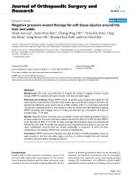
Anterior syndesmosis (oblique sagittal/axial PD-weighted fatsat sequence; ▶ Fig. 1.1 a): This oblique sagittal/axial angulation can display the full course of the anterior syndesmosis,
which descends obliquely from the distal tibia to the fibula.
This sequence will clearly show any fiber discontinuity or
hemorrhagic areas in the tibiofibular syndesmosis.
Tendon pathology in the hindfoot and midfoot (axial oblique
T1-weighted fat-sat after contrast administration; ▶ Fig. 1.1
b): The tendons in the hindfoot (flexor and extensor tendons,
and peroneal tendons) run at a 45° angle to the ankle joint.
The axial oblique T1-weighted fat-sat sequence after contrast
administration is prescribed at a 90° angle to the course of
the tendons to give an optimum cross-sectional view of the
tendons and their sheaths. This sequence and orientation will
clearly show increased contrast uptake in the tendon sheaths
or abnormal enhancement within those tendons that would
indicate increased vascularity due to advanced intratendinous
degeneration.
Morton neuroma (axial and coronal T1-weighted sequences
without contrast administration): These are the most important sequences for the evaluation of Morton neuroma. Due to
its high cellularity, this mass appears hypointense within the
hyperintense fat on unenhanced T1-weighted images and is
often conspicuous by its bulbous or fusiform shape in the
interdigital space. Often contrast administration adds little information, because Morton neuromas may show a variable
degree of vascularity. The key identifying feature is the interdigital location of the mass (between the second and third or
third and fourth metatarsal heads on the plantar side) and its
shape (usually bulbous in the axial T1-weighted sequence
and fusiform in the coronal sequence, extending into the
plantar soft tissue).
In summary, an optimum MRI examination of the foot can be
performed easily and routinely. Compromised image quality
is often a result of economic constraints. High image quality
requires a considerable investment of time, which is not always
justifiable on purely economic grounds.
1.2 Multidetector-Row Spiral Computed Tomography (CT)
Fig. 1.1 a, b Special sequences for MRI of the foot.
a The anterior syndesmosis is evaluated with an oblique sagittal scan.
b Tendon pathology is evaluated with an oblique axial
scan.
1.1.2 Post-Exercise MRI
1.2.2 Protocol
A common problem in patients with foot pain is the intermittent nature of the complaints in response to weight bearing and
exercise. Patients are often advised to rest the affected foot on
their initial visit to a foot specialist, and a subsequent MRI examination is usually performed during a stress-free interval.
Consequently, most patients are scanned at a time when they
are not experiencing symptoms. They give a history of complaints that occur during or after physical exertion or athletic
activity. In some cases MRI performed during an asymptomatic
interval may fail to detect the pathology (e.g., deeply situated
ganglia in the tarsal tunnel that exert a mass effect only during
exercise, or instability of the peroneal tendons).
For a post-exercise MRI study, the patient is told to perform
the exercise that typically causes the painful symptoms. If necessary the study is preceded by one or more units of running or
training exercises that are likely to reproduce the pain. MRI
scans are initiated only after the complaints have been elicited,
and IV contrast administration should be used.
Post-exercise MRI has not yet been fully evaluated in studies,
and its capabilities relative to “standard MRI” have not yet been
definitively assessed. Also, studies should be done only by an
experienced foot radiologist who will not misinterpret possible
epiphenomena such as physiologic joint effusions or venous dilatation. Nevertheless, post-exercise MRI may be a helpful study,
especially in athletes, in cases where prior images acquired elsewhere were negative and there is a new indication for MRI.
Isotropic voxels are necessary for optimum multiplanar reformatting (MPR) of the acquired data sets. Sample protocol:
● Slice thickness 0.5 mm
● Reconstruction increment 0.25 mm
● Pitch 0.875
● 120 kV
● 80 to 150 mA (use a reduced dose and strict selection criteria
in children)
1.2 Multidetector-Row Spiral
Computed Tomography (CT)
Images are reconstructed in three standard planes (axial, coronal and sagittal), while areas of special concern are evaluated in
selected magnified views.
1.2.3 Indications
●
●
●
U. Szeimies
1.2.1 Positioning
●
●
●
Comfortable supine position
Avoid motion artifacts
Scan only the affected foot in the supine position or with the
foot resting on the cassette
Initial work-up:
○ Fractures (to assess axial malalignment in ankle fractures
while clearly defining the fragments and looking for stepoffs), especially metatarsal fractures
○ Severe sprains with equivocal radiographic features
○ Neuroarthropathy
○ Osteoarthritis (evaluating the extent of degenerative changes)
○ CT as an adjunct to MRI (ganglion cyst, unexplained bone
marrow edema, further differentiation of tumors)
○ Coalition
○ As an aid to preoperative planning (e.g., calculation of the
tibial torsion angle)
Postoperative imaging (axial alignment, step-off in an articular
surface, internal fixation materials)
Follow-up:
○ Bony consolidation of fractures and nonunions
○ Localization and evaluation of internal fixation material
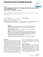
(screw in the joint space, loosening; ▶ Fig. 1.2)
1.2.4 Special Techniques
●
3D imaging; indications:
○ Complex fractures
○ Calcaneal fracture, evaluation of the subtalar joint surface
3
Imaging Techniques
Fig. 1.2 a, b Persistent pain after fusion of the
first tarsometatarsal joint in a 72-year-old
woman.
a Oblique coronal multiplanar reformatting
(MPR) image reconstructed along the screw
through the first tarsometatarsal joint shows a
fine zone of bone resorption around the arthrodesis screws (arrows). Bony consolidation around
internal fixation material and the bony attachment of the material can be assessed accurately
and with relatively few artifacts, even in small
joints.
b Coronal MPR of the midfoot demonstrates nonunion of the first tarsometatarsal joint.
Tarsometatarsal (Lisfranc) and midtarsal (Chopart) joint lines
Interrelationship of the fragments
○ Axial malalignment
Side-to-side comparison: Considered obsolete due to excessive
radiation exposure
CT examinations in children: Whenever possible, CT should be
replaced by MRI due to radiation concerns (e.g., for investigating epiphyseal plate injuries, bone fractures involving the epiphyseal plate, or coalition). CT should be used only if MRI
findings are equivocal.
○
○
●
●
Non–Weight-Bearing Radiographs of the
Foot, Stress Radiographs
Indications
Non–weight-bearing radiographs of the foot are obtained in patients with suspected fractures and for postoperative evaluations and stress views.
1.3 Radiography
Positioning
M. Walther
The patient lies on the X-ray table in a supine or lateral decubitus position (non–weight-bearing views are obtained only after
trauma or surgery):
● DP projection:
○ Film horizontal on the X-ray table
○ Foot position: patient lies supine with the foot flat on the
cassette
○ Beam centered on the second tarsometatarsal joint
○ Tube 0° vertical
○ If necessary, a forefoot adduction stress can be applied manually or with a mechanical apparatus (e.g., Telos device or
Scheuba device).
● Lateral view (▶ Fig. 1.4 a):
○ Film horizontal on the X-ray table
○ Foot position: patient lies in lateral decubitus on the X-ray
table with the affected foot down and resting on the
cassette
○ Central ray focused on the calcaneocuboid joint
○ Tube 0° vertical
● 45° oblique views from the lateral side (▶ Fig. 1.4 b):
○ Film horizontal on the X-ray table
○ Foot position: foot standing on the cassette and tilted 45°
medially
○ Beam centered on the second tarsometatarsal joint
○ Tube 0° vertical
● 45° oblique view from the medial side (e.g., an extra 45° inversion view is taken to evaluate the first tarsometatarsal joint
after surgical fusion):
○ Film horizontal on the X-ray table
1.3.1 Forefoot
Weight-Bearing Radiographs of the Foot in
Three Planes (▶ Fig. 1.3)
Indications
Standard radiographic series for the foot. Non–weight-bearing
views of the foot are obtained only after trauma or surgery.
Positioning
●
●
DP (dorsoplantar) projection:
○ Film flat on the floor
○ Patient standing on the cassette
○ Beam centered on the second tarsometatarsal joint
○ Tube 0° vertical
Lateral view:
○ Film perpendicular to the floor, touching the medial side of
the foot
○ Patient standing on the floor
○ Beam directed lateromedially, centered on the calcaneocuboid joint
○ Tube 0° horizontal
The determination of axial relationships on radiographs is subject to considerable variability. Couglin et al (2002) published a
technique for determining bone axes based on designated reference points in the diaphysis. This technique was adopted by the
4
AOFAS (American Orthopedic Foot and Ankle Society) as its
standard for surgery of the forefoot.
1.3 Radiography
Fig. 1.3 a–c Weight-bearing radiographs of the
foot in three planes. Standard series for evaluating deformities and degenerative diseases.
These radiographs are the basis for most reconstructive surgical procedures on the foot. Angle
determinations are all performed on weightbearing radiographs. This series illustrates a
hallux valgus deformity with degenerative
changes in the subsesamoid joint space.
a Lateral view.
b Oblique view.
c DP view.
○
○
○
Foot position: foot standing on the cassette and tilted 45°
laterally
Beam centered on the first tarsometatarsal joint
Tube 0° vertical
! Note
The stability of the calcaneocuboid joint can be evaluated on a
non–weight-bearing DP radiograph while a forefoot adduction
stress is applied. More than 10° of joint space opening is considered abnormal.
Toe Radiographs
Indications
Toe radiographs are obtained to evaluate toe injuries and other
pathology.
Positioning
●
●
●
DP projection
Lateral oblique projection
True lateral projection (rarely taken because the toes overlap
in that projection)
5
Imaging Techniques
Fig. 1.4 a, b Non–weight-bearing radiographs
of the forefoot in two planes. A weight-bearing
radiograph could not be obtained in this patient
due to severe arthritis of the first metatarsophalangeal joint.
a DP view.
b Oblique view.
●
applied with a strap to produce maximum dorsiflexion of
the toes
○ Beam centered on the first metatarsophalangeal joint
○ X-ray tube 0° vertical
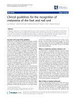
PA (posteroanterior) axial view of the sesamoids (▶ Fig. 1.5):
○ Horizontal film position
○ Foot position: patient lies prone with the knee supported
on a foam pad and the toes in maximum dorsiflexion
○ Beam centered on the first metatarsophalangeal joint
○ X-ray tube 0° vertical
! Note
Fig. 1.5 Radiographic view of the sesamoids in their sulci, usually
combined with radiographs of the foot in three planes. This view can
demonstrate degenerative changes in the subsesamoid joint space,
fragmentation due to sesamoid necrosis, subluxation of the sesamoids
due to hallux valgus, or sesamoid irritation by metal following hallux
surgery. The present image shows no abnormalities.
Visualization of the sesamoids in their sulci is particularly helpful for evaluating degenerative changes in the subsesamoid
joint space, unexplained complaints after hallux surgery, and
sesamoid osteonecrosis. The sesamoid views are supplemented
by radiographs of the big toe in three planes.
1.3.2 Hindfoot
Toe projections are analogous to projections of the foot, except
that the beam is centered on the second toe or on the toe with
the presumed pathology.
Radiographs of the Ankle Joint in Two Planes
Sesamoid Radiographs
These are the standard projections for evaluating pathology in
the talocrural joint.
Indications
Radiographs of the foot in three planes should be obtained in
all patients with presumed sesamoid pathology.
Indications
Positioning
●
Positioning
●
6
AP (anteroposterior) axial view of the sesamoids:
○ Horizontal film position
○ Foot position: patient lies supine with the heel on the film
plate, the ankle joint in 105° of plantar flexion, and traction
●
AP weight-bearing radiograph (▶ Fig. 1.6):
○ Film is vertical and behind the ankle joint
○ Foot position: patient stands with the heel against the cassette and the axis of the foot parallel to the central ray
○ Beam centered on the ankle joint
○ X-ray tube 0° horizontal
Weight-bearing mortise view:
○ Film is vertical and behind the ankle joint
1.3 Radiography
! Note
Oblique views in 45° of internal and external rotation supply additional information on the ankle mortise and talus. The internal
rotation view is good for evaluating the distal fibula and subfibular region. The external rotation view clearly displays the posteromedial talus.
Non–Weight-Bearing Radiographs of the
Ankle joint, Stress Radiographs
Indications
●
●
Suspected fracture after trauma
Stress views for evaluating (chronic) capsuloligamentous
instabilities about the ankle joint
Positioning (▶ Fig. 1.7 and ▶ Fig. 1.8)
●
●
Fig. 1.6 AP weight-bearing radiograph of the ankle joint reveals
degenerative joint changes with varus deformity.
Foot position: patient stands with the heel against the cassette and the foot rotated internally until the axis of the ankle joint is parallel to the cassette
○ Beam centered on the ankle joint
○ X-ray tube 0° horizontal
Lateral ankle view:
○ Film is vertical and medial to the ankle joint
○ Foot position: patient stands with the medial side against
the cassette
○ Beam centered on the ankle joint
○ X-ray tube 0° horizontal
○
●
●
Non–weight-bearing AP projection:
○ Film horizontal on the X-ray table
○ Foot position: patient lies supine on the table with the heel
resting on the cassette (axis of the foot is parallel to the
central ray)
○ Beam centered on the ankle joint
○ X-ray tube 0° vertical
○ If desired, a varus or valgus stress can be applied to the
ankle manually or with a mechanical apparatus (e.g., Telos
device or Scheuba device).
Non–weight-bearing mortise view:
○ Film horizontal on the X-ray table
○ Foot position: patient lies supine on the table with the heel
resting on the cassette (axis of the ankle joint is parallel to
the cassette)
○ Beam centered on the ankle joint
○ X-ray tube 0° vertical
○ If desired, a varus or valgus stress can be applied manually
or with a mechanical apparatus (e.g., Telos or Scheuba
device).
Non–weight-bearing ankle lateral view:
○ Film horizontal on the X-ray table
○ Foot position: patient is in lateral decubitus on the X-ray
table with the affected foot down and resting on the
cassette (axis of the foot is parallel to the central ray)
○ Beam centered on the ankle joint
○ X-ray tube 0° vertical
○ If desired, a drawer test can be performed by applying
pressure to the front of the distal tibia while manually or
mechanically stabilizing the calcaneal tuberosity.
Stress radiographs can be obtained by applying the stress manually or with a mechanical device. The standard pressure is
15 kPa. In an acute injury, stress radiographs are rewarding only
when analgesia is administered (e.g., local anesthesia of the
7
Imaging Techniques
Fig. 1.7 a, b Stress radiograph of the ankle
joint. Stress views are feasible only in patients
without ankle pain. Increased joint space opening
is diagnostic of capsuloligamentous laxity or a
ligament tear. False-negative results are a possibility. Stress radiographs have become largely
obsolete in the acute diagnosis of ligament tears.
a DP view.
b Lateral view.
Fig. 1.8 a, b Non–weight-bearing radiographs
of the ankle joint in two planes. These are the
standard views for acute injuries, especially for
suspected fractures. These radiographs show a
fracture of the fibula and a chip fracture of the
posterior tibial margin.
a DP view.
b Lateral view.
capsule and ligaments). Today, stress radiographs are of minor
importance in the treatment algorithm for a lateral ankle
sprain. Equivocal findings may be resolved by a side-to-side
comparison, but this requires a higher radiation dose and
should never be carried out to compensate for a lack of knowledge in radiographic anatomy or morphology.
! Note
The following signs on stress radiographs are considered
abnormal:
● Anterior displacement of the talus > 2 mm in a side-to-side
comparison
● Absolute talar displacement > 4 mm
● Lateral joint space opening > 10° in a side-to-side comparison
● Difference in the distance from the lateral distal talar margin
to the fibular articular surface > 3 mm
8
Lateral radiographs are obtained in maximum dorsiflexion
or plantar flexion with anterior or posterior impingement. AP
radiographs are taken with eversion and dorsiflexion in patients with a suspected syndesmotic injury.
Broden View (▶ Fig. 1.9)
Indications
The Broden view is used to display the posterior facet of the
subtalar joint.
Positioning
●
Medial oblique view:
○ Film position horizontal on the X-ray table
○ Foot position: patient lies supine with the foot in internal
rotation (45°) and the ankle joint at a 90° angle supported
on a foam wedge
1.3 Radiography
Radiographs of the Calcaneus in Two Planes
Indications
Radiographs of the calcaneus in two planes are performed in
patients with calcaneal fractures, after bony corrections, and in
the diagnosis of Haglund exostosis and traction spurs.
Positioning
●
●
DP calcaneus axial projection:
○ Film position horizontal on the X-ray table
○ Foot position: patient stands on the film with the tube behind the leg
○ Central ray is focused between the Achilles tendon insertion
and the ankle joint
○ X-ray tube is angled anteriorly at a 25° angle from the
vertical
Calcaneus lateral view:
○ Film is perpendicular to the floor, placed against the medial
aspect of the foot
○ Foot position: patient stands on the floor
○ Central ray from lateral to medial, centered on the
calcaneus
○ X-ray tube: 90° from the perpendicular
! Note
Lateral views taken with 30° of internal and external rotation
can detect calcifications on the calcaneal margins. Alternatively,
CT or MRI can be used in clinically suspicious cases with negative radiographs.
Fig. 1.9 Broden stress view. The Broden view is used to evaluate the
stability of the subtalar joint in response to an inversion stress. This
image shows slight joint space opening with rounded bone fragments
on the lateral process of the talus following a sprain injury.
Central ray is focused between the fibular apex and base of
the fifth metatarsal
○ X-ray tube: views are taken at 10°, 20°, 30°, and 40° angles
from the vertical with the central ray angled cephalad
Lateral oblique view:
○ Film position horizontal on the X-ray table
○ Foot position: patient lies supine with the foot in external
rotation (45°) and the ankle joint at a 90° angle supported
on a foam wedge
○ Central ray is focused between the medial malleolus and
the tuberosity of the navicular bone
○ X-ray tube: views are taken at a 15° and 18° angle from the
vertical with the central ray angled cephalad
○
●
Hindfoot Alignment View (Saltzman View,
▶ Fig. 1.10)
Indications
The Saltzman view is for evaluating the axial alignment of the
hindfoot.
Positioning
●
●
●
●
! Note
The Broden view is a helpful intraoperative view during the
open reduction and internal fixation of calcaneal fractures. CT
has largely replaced the Broden view as a preoperative study.
The medial oblique view can be obtained with a varus stress to
evaluate subtalar joint stability.
Film position: angled 20° from the vertical and 90° to the
central ray
Foot position: patient stands on a platform with the tube behind the leg and the cassette anterior to the foot
Beam is centered on the ankle joint
X-ray tube is angled 20° from the horizontal in a plantar
direction
! Note
Hindfoot alignment views are an important aid in the work-up
of calcaneal varus or valgus deformity and in the planning of
hindfoot corrections.
9
Imaging Techniques
Fig. 1.10 a, b Saltzman view. The Saltzman view
is used to evaluate calcaneal alignment. It has
become increasingly important in recent years in
the treatment of hindfoot deformities and is
performed with weight bearing along with
radiographs of the ankle joint in two planes.
a Patient with hindfoot valgus and forefoot
abduction.
b Appearance following surgical correction by a
calcaneal sliding osteotomy and calcaneal lengthening.
1.4 Ultrasound
10
H. Gaulrapp
●
Even in the foot and ankle, diagnostic ultrasound provides an
“extended clinical finger,” which should be performed personally by the clinical examiner in order to gain maximum
information.
The patient is placed in a supine or prone position, supported
if necessary with a padded roll. The affected structure is always
scanned in two planes—longitudinal and transverse—using a
7.5- to 15-MHz linear transducer. A stand-off may be used on
irregular surfaces and will improve resolution in the unfavorable near-field region, though it may sometimes cause troublesome reverberations. The use of a fluid-filled glove is not
recommended owing to the presence of small air bubbles. The
field of view and focus should be optimized for the region of interest (size, depth).
Besides the few standard sections recommended for the
ankle joint by the DEGUM (German Society for Ultrasound in
Medicine), additional planes have proven useful for scanning
specific joint areas, tendons, and especially ligamentous
structures.
Strengths of ultrasound:
● It can demonstrate fluids, soft tissues, joints, and bony
surfaces.
● The power Doppler mode provides information on vascularity
(e.g., angiogenesis in synovitis).
● Real-time imaging permits a unique dynamic–functional
analysis of mobility and stability in joint compartments and
●
of the muscle–tendon apparatus under constant visual
control.
Aspirations, injections, and biopsies are safer and more accurate when performed with ultrasound guidance or assistance.
The technique is rapidly available at low cost.
Weaknesses of ultrasound:
Inability to penetrate bony or calcified structures
● Poor visualization of deeper structures
● Poorer lateral resolution than MRI, with comparable axial
resolution
●
Ultrasound can provide the experienced examiner with a
wealth of additional information within a short time, allowing
for the prompt and purposeful initiation of treatment while
eliminating the need for costly or invasive tests:
● It can detect and differentiate between articular or periarticular swelling, effusion or hemarthrosis, seroma or hematoma,
and exudative or proliferative synovitis.
● It can determine accessibility to percutaneous aspiration or
biopsy; compression and pressure-release testing with the
probe.
The following can also be discerned:
Tears of the joint capsule and ligaments: complete, partial,
stability testing, measurements
● Heel pain: differentiation of lesions affecting the Achilles tendon, bursa, traction spur, exostosis, Haglund heel
● Tendon lesions: differentiation of complete, partial, tendinopathy, peritendinous changes, displacement, reparability
●
1.5 Bibliography
1.5 Bibliography
Radiography
Christman RA. Foot and Ankle Radiology. St. Louis: Churchill Livingstone; 2003
Cobey JC. Posterior roentgenogram of the foot. Clin Orthop Relat Res 1976; 118:
202–207
Coughlin MJ, Saltzman CL, Nunley JA. Angular measurements in the evaluation of
hallux valgus deformities: a report of the ad hoc committee of the American Orthopaedic Foot & Ankle Society on angular measurements. Foot Ankle Int 2002;
23: 68–74
Saltzman CL, el-Khoury GY. The hindfoot alignment view. Foot Ankle Int 1995; 16:
572–576
Ultrasound
Gaulrapp H, Binder C. Grundkurs Sonografie der Bewegungsorgane. Munich: Elsevier; 2011
Gaulrapp H, Szeimies U. Diagnostik der Gelenke und Weichteile: Sonographie oder
MRT. Munich: Elsevier; 2008
11