Ebook Imaging of the hip & bony pelvis - Techniques and applications: Part 2
Bạn đang xem bản rút gọn của tài liệu. Xem và tải ngay bản đầy đủ của tài liệu tại đây (16.78 MB, 195 trang )
Bony Trauma 1: Pelvic Ring
217
14 Bony Trauma 1: Pelvic Ring
Philip Hughes
CONTENTS
14.1
14.2
14.2.1
14.2.2
14.2.3
14.2.4
14.2.5
14.2.6
14.2.7
14.3
14.3.1
14.3.2
14.3.3
14.3.4
14.3.5
14.3.6
14.4
14.5
Introduction 217
Pelvic Ring Fractures 217
Anatomy 217
Techniques 218
Classification of Pelvic Fractures 218
Force Vector Classification of Pelvic Ring
Injury 219
Pelvic Stability 224
Diagnostic Accuracy of Plain Film and Computed
Tomography in Identification of Pelvic Fractures 224
Risk Analysis and the Force Vector
Classification 224
Acetabular Fractures 224
Acetabular Anatomy 225
Radiographic Anatomy 225
Classification 227
Basic Patterns 227
Complex or Associated Fracture Patterns 229
Relative Accuracy of the AP Radiograph, Oblique
Radiographs and Computed Tomography 230
Avulsion Fractures 233
Conclusion 234
References 235
14.1
Introduction
Major pelvic ring and acetabular fractures are predominantly high energy injuries and consequently
are not infrequently associated with injury to the
pelvic viscera and vascular structures. Mortality
and morbidity related to these injuries primarily
results from haemorrhage, the outcomes have however improved through the use of external fixation
devices and other compression devices. Recognition of the type and severity of injuries, particularly
those involving the pelvic ring, is essential to the
application of corrective forces during external or
internal fixation techniques. The pattern and severity of injury also predict the probability of pelvic
P. Hughes, MD
Consultant Radiologist, X-Ray Department West, Derriford
Hospital, Derriford Road, Plymouth, PL6 8DH, UK
haemorrhage and visceral injury which can prove
influential when assessing the likely site of haemorrhage and the appropriateness of further cross-sectional imaging or operative intervention.
Acetabular fractures can be classified into simple
and complex patterns which require a thorough
understanding of the regional anatomy and the associated radiological correlates. The patterns of fracture determine the operative approach and although
predominantly determined by plain film views (AP
and Judet obliques) are often supplemented by CT
(2D, MPR and 3D surface reconstructions). CT is
also required to identify intra-articular fragments
that are not usually identifiable on plain films and
secondly to assess postoperative alignment of articular surfaces. MR may also be performed following
femoral head dislocations or acetabular fracturedislocations where viability of the femoral head is
questioned and would alter management.
The final group exhibiting a distinctive pattern
of pelvic fractures to be considered include avulsion
injuries which are encountered predominantly in
individuals following sporting activity and are more
frequent in the immature skeleton. Stress fractures
and pathological fractures of the pelvis are covered
in Chaps. 16 and 22, respectively.
14.2
Pelvic Ring Fractures
14.2.1
Anatomy
The pelvic ring comprises the sacrum posteriorly
and paired innominate bones, each formed by the
bony fusion of the ilium, ischium and pubic bones,
each having evolved from independent ossification
centres. The sacrum and innominate bones meet at
the sacroiliac articulations, and the pubic bones at
the fibrous symphysis pubis. The integrity of the
bony ring is preserved by ligaments, an apprecia-
P. Hughes
218
tion of which is essential to the understanding of
patterns of injury and the assessment of stability of
injured pelvic ring.
Anteriorly the symphysis is supported predominantly by the superior symphyseal ligaments
(Fig. 14.1a). Posteriorly the sacroiliac joints are
stabilised by the anterior and posterior sacroiliac
ligaments (Fig. 14.1b). The posterior ligaments are
amongst the strongest ligaments in the body, running from the posterior inferior and superior iliac
spines to the sacral ridge. The superficial component of the posterior sacroiliac ligament runs inferiorly to blend with the sacrotuberous ligaments. The
sacrospinous and sacroiliac ligaments support the
pelvic floor and oppose the external rotation of the
lilac blade. The iliolumbar ligaments extend from
the transverse processes of the lower lumbar vertebrae to the superficial aspect of the anterior sacroiliac ligaments and can avulse transverse processes
in association with pelvic fractures.
Important arterial structures vulnerable to
injury include the superior gluteal artery in the
sciatic notch which may be disrupted by shearing
forces exerted during sacroiliac joint diastasis. The
obturator and pudendal arteries are not uncommonly injured during lateral compression injuries
resulting in comminution of the anterior pubic arch.
Other commonly injured vessels include the median
and lateral sacral, and iliolumbar arteries.
Urogenital injuries are also commonly associated
with pelvic ring injury consequent upon the close
association of the urethra and symphysis and pubic
rami and bladder. Anterior compression forces are
more commonly responsible for urethral injury,
usually affecting the fixed membranous portion of
the urethra.
14.2.2
Techniques
The AP pelvic radiograph is one of the three basic
radiographs performed as part of the ATLS protocol
in the setting of major trauma, the other radiographs
including views of the cervical spine and chest. The
AP views demonstrate the majority of pelvic fractures, excepting intra-articular fragments (Resnik
et al. 1992). The pelvic inlet and outlet views supplement the AP view in pelvic ring fractures, the former
demonstrating rotation of the pelvis, additional
fractures of the pubic rami and compression fractures of the sacral margins while the latter assesses
craniocaudal displacement particularly in vertical
shear injuries. The widespread use of CT in trauma
cases in general and its invariable use in pelvic fractures to assess both severity and requirement for
operative fixation have essentially eliminated the
requirement for inlet and outlet views. CT technique
will vary with the type of scanner used but should
include section thicknesses between 2.5–5.0 mm.
The mAs can be reduced when the scan is purely
performed for the purposes of bony anatomy from
the standard around 120 mAs to 70 mAs.
14.2.3
Classification of Pelvic Fractures
The classification of pelvic fractures has changed
during the last two decades to more accurately
reflect the mechanism of injury and quantify the
degree of instability. Malgaine, straddle and openbook fractures, used as descriptive terms prior to
the 1980s in most standard texts, failed to provide
a
b
Fig. 14.1. a AP view of pelvic ligaments and (b) pelvic inlet perspective demonstrating anterior and posterior sacroiliac ligaments
Bony Trauma 1: Pelvic Ring
precise detail relating to pelvic injury and did not
emphasise the importance of the unseen ligamentous structures.
Penall et al. (1980) first described the correlation between the pattern of fracture and the direction of the applied traumatic force. They proposed
the forced vector classification of pelvic fractures,
identifying anteroposterior compression (AP), lateral compression (LC) and vertical shear as pure
bred forces responsible for specific patterns of injury.
Tile (1984) subsequently documented the high risk
of pelvic haemorrhage particularly in injuries to the
posterior pelvis and the advantage of this systematic classification when applying external fixation
devices.
Young et al. (1986) further refined the classification identifying a constant progression or pattern
to pelvic injury within each vector group which
was both easily remembered and more importantly
accurately reflected the degree of instability based
predominantly on the imaging appearances. Later
studies also linked probability of pelvic haemorrhage
and bladder injury to the pattern of fracture allowing
an element of risk stratification to be undertaken in
relation to haemodynamically unstable patients with
pelvic injury (Ben-Menachem et al. 1991).
14.2.4
Force Vector Classification of Pelvic Ring Injury
There are three primary vectors responsible for
pelvic injuries, Young et al. (1986) identified an LC
pattern in 57% of patients, AP compression in 15%
and a vertical shear pattern in 7%. The remainder,
22%, demonstrated hybrid features as a result of
oblique or combined multidirectional forces which
are referred to as ‘complex’ fractures.
219
ments. The final phase if further force is applied is
disruption of the posterior sacroiliac ligaments effectively detaching the innominate bone from the axial
skeleton. The extent of posterior pelvic injury allows
AP injuries to be stratified into one of three groups
reflecting increasing severity and instability.
14.2.4.1.1
AP Type 1
This is the commonest type of AP compression
injury, the impact of the trauma is confined to the
anterior pubic arch and the posterior ligaments are
intact. Radiographs demonstrate either fractures of
the pubic rami which characteristically have a vertical orientation (Fig. 14.2) or alternatively disruption
and widening of the symphysis. Integrity of the posterior ligaments restricts the symphyseal diastasis
to less than 2.5 cm. Compression devices can however re-oppose the margins of a diastased symphysis, caution should therefore be exercised in ruling
out injury on the basis of a normal AP radiograph
without correlation to the clinical examination. In
practice this eventuality occurs rarely. CT scans can
occasionally over-estimate the extent of injury of a
true type 1 injury by demonstrating minor widening of the anterior component of the sacroiliac joint,
which it is postulated, results from stretching rather
than disruption of the anterior sacroiliac ligaments
(Young et al. 1986). These injuries are essentially
stable and require non-operative management.
14.2.4.1.2
AP Type 2
These comprise anterior arch disruption as described
above with additional diastasis of the anterior aspect
14.2.4.1
Anteroposterior Compression Injuries
These injuries are commonly the result of head on
road traffic accidents or compressive forces applied
in the AP plain. The effect of this force is to externally rotate the pelvis, the posterior margin of the
sacroiliac joint acting as the pivot.
This force will initially result in fractures of the
pubic rami or disruption of the symphysis and symphyseal ligaments. Progressive force will further
externally rotate the pelvis disrupting the sacrotuberous, sacrospinous and anterior sacroiliac liga-
Fig. 14.2. AP type 1 injury characterised by vertical fracture line
in inferior pubic ramus typical of AP compression injury
P. Hughes
220
of the sacroiliac joint space commonly referred to as
an “open book” injury or “sprung pelvis”(Fig. 14.3).
Sacroiliac diastasis is more accurately assessed by
CT than plain film (Fig. 14.4). These injuries exhibit
partial instability being stable to lateral compressive forces (internal rotation) but unstable to AP
compressive forces (external rotation).
14.2.4.1.3
AP Type 3
This pattern of injury result in total sacroiliac joint
disruption (Fig. 14.5). Features described in the
less severe types 1 and 2 injuries are present but
in addition the sacroiliac joint is widely diastased
posteriorly as well as anteriorly due to the posterior
sacroiliac ligament rupture (Fig. 14.6). The hemipelvis is unstable to all directions of force, and usually requires operative stabilisation. Variants on the
type three pattern include preservation of the sacroiliac joint integrity at the expense of sacral or iliac
fracture (Fig. 14.7).
Complications of AP compression injuries
include bladder rupture, usually intra-peritoneal
type, which requires cystography for confirmation
(Fig. 14.8) and vascular injury, particularly affecting the superior gluteal artery due to shear forces in
the sciatic notch.
the symphysis is disrupted and overlaps. Three
types of LC fracture are recognised.
14.2.4.2.1
LC Type 1
This represents the least severe injury pattern and is
sustained by lateral force applied over the posterior
pelvis causing internal rotation of the innominate
bone which pivots on the anterior margin of the
sacroiliac joint (Fig. 14.9). Radiographic features
include pubic rami fractures, which are oblique,
segmental (Fig. 14.10), frequently comminuted and
rarely overlapping (Fig. 14.11) in contrast to the vertical fractures of AP compression injuries. Compression fractures of the anterior margin of the sacrum
14.2.4.2
Lateral Compression Injuries
The commonest pattern of pelvic injury is discussed
in the review of Young et al. (1986). Most patients
with this mechanism of injury demonstrate pubic
rami fractures. Exceptions are encountered when
Fig. 14.4. CT scan demonstrating AP type 2 injury (openbook). Diastasis of the anterior part of the left sacroiliac
hinged on its posterior margin as the posterior sacroiliac ligament remains intact
Fig. 14.3. AP type 2 injury
Fig. 14.5. AP type 3 injury
Bony Trauma 1: Pelvic Ring
221
a
b
Fig. 14.6a,b. a AP type 3 injury comprising wide diastasis of the symphysis (> 2.5 cm) and diastased sacroiliac joint (black
arrows). b CT demonstrating AP type 3 injury, wide diastasis throughout right sacroiliac joint, anterior and posterior sacroiliac
ligaments are disrupted
Fig. 14.7. AP type 3 variant. Symphyseal diastasis, intact sacroiliac joints but midline sacral fracture (arrow)
Fig. 14.9. LC type 1
Fig. 14.8. Cystogram demonstrating intraperitoneal bladder rupture. The compression device has reduced the pelvic
diastasis, pelvic instability cannot be excluded by a normal
radiograph
Fig. 14.10. LC type 1 injury demonstrating oblique (black
arrow) and buckle fracture (white arrow) indicative of lateral
compression
P. Hughes
222
Fig. 14.11. LC type 1 injury overlapping pubic rami
Fig. 14.12. CT demonstrating LC type 1 injury, compression
fracture of the anterior sacral margin (white arrow)
are better demonstrated by CT than plain films
(Fig. 14.12) (Resnik et al. 1992). These injuries have
little resultant instability and do not require operative management.
14.2.4.2.2
LC Type 2
The lateral compressive force in type 2 injuries is
usually applied more anteriorly (Fig. 14.13). The
pubic rami injuries are as described for type 1 but as
the pelvis internally rotates pivoting on the anterior
margin of the sacroiliac joint the posterior sacroiliac
ligaments are disrupted. An alternative outcome if
the strong posterior ligaments remain intact is for
the ilium to fracture. This latter pattern is referred
to as a type 2a injury (Fig. 14.14) as it was the first
recognised but in reality the posterior sacroiliac
joint diastasis, type 2b injury (Fig. 14.15), is the
more commonly encountered pattern.
14.2.4.2.3
LC Type 3
This pattern of injury often referred to as the “windswept” pelvis (Fig. 14.16), results from internal rotation on the side of impact and external rotation on
the other, and is often the result of a roll-over injury.
The associated ligamentous injury and radiographic
features combine lateral compression injuries on one
side and AP compression on the other, as described
in the preceding text.
Recognition of lateral compression injuries is
important as external fixation devices and other
methods of stabilisation tend to exert internal compressive forces that could exacerbate deformity and
Fig. 14.13. LC type 2
increase the risk of progressive haemorrhage in this
group.
14.2.4.3
Vertical Shear
Vertical shear injuries are usually the result of a
fall or jump from a great height but loads transmitted through the axial skeleton from impacts to
the head and shoulders can have identical consequences. The injury is typically unilateral comprising symphyseal diastasis or anterior arch fracture
and posterior disruption of the sacroiliac joint with
cephalad displacement of the pelvis on the side of
impact (Fig. 14.17). Variants include disruption of
the sacroiliac joint opposite to the side of impact or
fracture of the sacrum.
Vertical shear injuries are invariably severe in
that all ligaments are disrupted, the pelvis being
totally unstable. There are no subcategories in this
Bony Trauma 1: Pelvic Ring
223
Fig. 14.15. CT demonstrating avulsion fracture of the posterior ilium by the posterior sacroiliac ligament (LC type 2b
injury)
a
b
Fig. 14.14a,b. Pelvic radiograph (a) and CT scan (b) demonstrating LC type 2a injury. Oblique superior ramus fracture
and iliac blade fracture on plain film (white and black arrows,
respectively). CT demonstrates intact sacroiliac joint and fractured ilium
injury type. Radiographs demonstrate ipsilateral
or contralateral pubic rami fractures, which have a
vertical orientation similar to that described in AP
compression injuries. The sacroiliac joint is also
disrupted but the main differentiating feature from
AP injuries is cephalad displacement of the pelvis
on the side of impact. Careful attention to the relative positions of the sacral arcuate lines and lower
border of the sacroiliac joint is a good guide to
malalignment.
a
b
Fig. 14.16a,b. LC type 3 injury: Windswept pelvis. LC injury on
side of impact (a) and AP injury on the “roll-over” side (b)
14.2.4.4
Complex Injuries
Complex patterns are not uncommon and when
reviewed the majority will demonstrate a predominate pattern usually an LC type. Recognition of the
complexity is important as external fixation devices
and operative intervention will have to apply the
appropriate corrective forces.
P. Hughes
224
Fig. 14.17. Vertical shear pattern of injury. Disrupted symphysis and sacroiliac joint (black arrows), lines drawn through
sacral foramen and symphysis highlight the extent of cephalad
displacement on the side of impact
14.2.5
Pelvic Stability
Stability depends on integrity of the bony ring and
supporting ligaments. Tile (1984) demonstrated
that in AP compression disruption of the symphysis
and its ligaments will allow up to 2.5 cm of diastasis.
Widening of the symphysis by more than 2.5 cm
is only achieved by disruption of the sacrotuberous, sacrospinous and anterior sacroiliac ligaments.
Total pelvic instability only results if the posterior
sacroiliac ligaments are also disrupted. It can be
appreciated therefore that stability or more precisely
instability of the pelvis represents a spectrum dependent on the extent of disruption of the bony ring and
ligaments. A sequential graded pattern of instability
also applies to lateral compression injuries
14.2.6
Diagnostic Accuracy of Plain Film and
Computed Tomography in Identification of
Pelvic Fractures
Considerable variation exists in the accuracy of
plain radiographic evaluation of pelvic fractures.
A 6-year retrospective review identified that plain
films failed to diagnose 29% of sacroiliac joint disruptions, 34% of vertical shear injuries, 57% of sacral
lip fractures and 35% of sacral fractures (Montana
et al. 1986). Computed tomography (CT) was used as
the gold standard and considerably improved diag-
nostic accuracy. When the films were re-reviewed by
this group applying the force vector classification,
with particular attention to sacral alignment and
detail, their accuracy increased, the vertical shear
injuries benefited most, accuracy of identification
increasing to 93%.
Resnik et al. (1992) prospectively evaluated a
similar number of patients with pelvic fractures
presenting over an 8-month period. In all, 160 fractures were identified in total with CT, of these only
9% were not identified prospectively. This group
included sacroiliac joint diastasis, sacral lip fractures, iliac and pubic rami fractures, but all were
subtle and none altered the management decision.
Acetabular fractures were also evaluated, 80% of
intra-articular fractures could not be identified on
plain film indicating the essential requirement of
CT in this subset of patients.
These studies identify firstly the importance of
an understandable system of classification as an
adjunct to improving performance and secondly the
benefits of regular exposure to pelvic trauma in the
latter study, which improves familiarity with injury
pattern and subtle signs associated with pelvic
trauma. Plain films will always remain the initial
assessment in the emergency room, and should allow
most fractures to be appreciated. CT is essential preoperatively and should also be considered earlier in
the diagnostic work-up if there are clinical doubts or
if trauma exposure and expertise is limited.
14.2.7
Risk Analysis and the Force Vector Classification
Ben-Menachem (1991) analysed the outcomes of
patients with pelvic trauma. In type 1 injuries due
to either lateral or AP compression the risk of severe
haemorrhage was less than 5%. Conversely the risk
of severe haemorrhage in the AP type 3 injury was
53%, 60% in LC type 3, 75% in vertical shear and
56% in complex injuries. This probability data,
whilst not an absolute, enables an informed judgement on the likelihood of pelvic haemorrhage as an
alternative to other visceral injury.
14.3
Acetabular Fractures
Acetabular injuries have complex fracture lines
and in order to accurately describe these injuries
Bony Trauma 1: Pelvic Ring
225
according to the classification described by Judet et
al. (1964) and Letournel (1980), a comprehensive
understanding of the three-dimensional acetabular
anatomy is required. It is inadequate to report an
acetabular injury as “complex fracture as shown”
as an accurate description using the aforementioned
classification determines the requirement for surgery and the operative approach.
14.3.1
Acetabular Anatomy
The acetabulum comprises two columns (posterior
and anterior) and two walls (posterior and anterior)
which are connected to the axial skeleton by the sciatic buttress (Fig. 14.18). The anterior column is long
and comprises the superior pubic ramus continuing
cephalad into the iliac blade. The posterior column
is shorter and more vertical extending cephalad
from the ischial tuberosity into the ilium.
greater sciatic notch. It defines the anterior part of
the pelvis which includes the anterior column, disruption of this line as will be discussed can result
from fractures other than anterior column injury.
The ilioischial line runs vertically from the greater
sciatic notch past the cotyloid recess through the
ischial tuberosity and comprises the posterior supportive structures of the acetabulum including the
posterior column.
The anterior wall crosses the acetabulum
obliquely and is less substantial and more medially
positioned than the posterior wall which is lateral
and more vertically orientated. The obturator ring
if intact or not breached at two points excludes the
14.3.2
Radiographic Anatomy
Several important lines are identifiable on the
anteroposterior radiograph, these include the iliopectineal (iliopubic) line, the ilioischial line and the
margins of the anterior and posterior walls of the
acetabulum (Fig. 14.19). The integrity of the obturator ring is also an important factor in fracture classification. The iliopectineal line runs along the superior margin of the superior pubic ramus towards the
a
b
Fig. 14.19. Radiographic lines essential to identification and
classification of acetabular fractures. Iliopectineal (iliopubic)
line (white arrows), ilioischial line (black arrows), posterior
acetabular wall (black arrowhead), anterior acetabular wall
(white arrowhead) and obturator ring circled
c
Fig. 14.18a–c. Acetabular (column) anatomy. Pink shaded area represents short posterior column (a), anterior column shaded
blue (b) and enclosing roof, anterior and posterior walls supported between the columns (c)
P. Hughes
226
a
b
c
d
Fig. 14.20a–d. Serial CT sections through the acetabulum, pink shading representing posterior column and blue the anterior
column
a
b
c
d
e
f
g
h
i
j
Fig. 14.21a–k. Elementary and complex patterns of acetabular fracture. Elementary group: (a) posterior wall; (b) anterior wall;
(c) posterior column; (d) anterior column; (e) transverse. Complex group: (f) posterior column and posterior wall; (g) both
columns; (h) transverse and posterior wall; (i) T-shaped; (j) anterior column and posterior hemi-transverse
possibility of a column fracture irrespective of disruption to the iliopectineal or ilioischial lines.
Oblique radiographic views (Judet pair) are often
requested to gain additional detail. These views are
referred to as the iliac oblique (IO) view which demonstrates the ilium en face and the obturator oblique
(OO) view. The IO view improves evaluation of the
anterior wall, posterior column and blade of the
Bony Trauma 1: Pelvic Ring
ilium. The OO view demonstrates the posterior wall,
anterior column (lower part), obturator ring and the
“spur” sign in double column injuries.
CT can provide additional detail regarding intraarticular fragments and supportive data regarding
column involvement and interruption of the obturator ring. Figure 14.20 demonstrates the corresponding CT locations of the column anatomy.
14.3.3
Classification
The Judet and Letournel classification is widely
accepted and is based on interpretation of the morTable 14.1. Diagnostic check list in acetabular fractures
1. Obturator ring (OR) fracture
(a) Anterior column (OR and iliopectineal line disruption)
(b) Posterior column (OR and ilioischial line disruption)
(c) T-shaped (OR and transverse acetabular fracture)
2. Iliopectineal line disrupted
(a) Anterior column (coronal fracture plane)
(b) Transverse and posterior wall
3. Ilioischial line disrupted
(a) Posterior column (coronal fracture plane)
(b) Anterior column and posterior hemi-transverse
4. Both iliopectineal and ilioischial lines disrupted
(a) Transverse (splits acetabulum into upper and lower
halves)
(b) T-shaped (as above with vertical fracture disrupting
OR)
(c) Bi-column (Sciatic strut disconnected from acetabulum,
Spur sign)
5. Posterior wall fracture
(a) Posterior wall (Isolated, if ilioischial and iliopectineal
lines intact)
(b) Posterior wall and column (as above and disrupted
ilioischial line)
6. Anterior wall fracture
(a) Anterior wall (Isolated, if ilioischial and iliopectineal
lines intact)
7. Fracture orientation
(a) Coronal, splitting acetabulum into anterior and posterior segments
Column fracture (anterior or posterior)
(b) Transverse, splitting acetabulum into upper and lower
segments
Transverse or T-shape fracture
8. Spur sign
Bi-column fracture
9. Fragments
Not specific to type of fracture most common in posterior
wall fractures
227
phological patterns of fracture using AP and Judet
views. CT provides additional information regarding
fracture orientation and intra-articular fragments.
CT multiplanar reformats and surface reconstructions improve diagnostic accuracy particularly for
inexperienced observers but systematic analysis of
plain films and transverse CT images alone should
allow most fractures to be classified (Brandser and
Marsh 1998)
The acetabular classification divides fractures
into a basic or elementary group, which include a
single main fracture line and a complex or associated
group representing combinations of the elementary
patterns (Fig. 14.21). There are five elementary fracture patterns, posterior column, anterior column,
posterior wall, anterior wall and transverse. Complex patterns most commonly encountered include
posterior column and posterior wall, both column,
and transverse with posterior wall fracture. The less
common complex patterns include anterior column
with posterior hemi-transverse and T-shaped. Variations including degree of comminution and extension into the ilium require separate description.
Table 14.1 provides a diagnostic check list facilitating accurate assessment and classification of acetabular fractures.
14.3.4
Basic Patterns
14.3.4.1
Posterior Wall Fracture
Posterior wall fractures are one of the commonest acetabular injuries, either as an isolated injury
(Fig. 14.22) or in combination with other fractures.
They are sustained most frequently through direct
compression of the posterior wall by the femoral
head a situation encountered in a “dash-board”
injury resulting from a frontal impact and are not
uncommonly associated with posterior dislocation
of the femoral head. The posterior wall fracture can
be appreciated on AP radiographs but the OO view
often improves visualisation. The size and comminution of the posterior fracture determines the
prognosis and risk of re-dislocation or instability.
CT is invaluable therefore in assessing the size of the
posterior wall defect relative to the overall posterior
wall depth. Fractures which constitute greater than
40% of the posterior wall represent an indication for
operative reduction and internal fixation (Keith et
al. 1988) (Fig. 14.23).
P. Hughes
228
tively remain intact. CT excludes significant steps in
the cortex or intra-articular fragments which would
indicate a requirement for open reduction.
14.3.4.3
Anterior Column Fractures
Fig. 14.22. Posterior wall fracture: AP radiograph demonstrating posterior wall fracture (white arrow)
Column fractures cross the acetabulum in a coronal
oblique orientation dividing the acetabulum into anterior and posterior elements (Fig. 14.24). The cephalad
end of the fracture exits anteriorly disrupting the iliopectineal line and extends into the iliac blade a variable
distance. The obturator ring is invariably fractured
in column injuries, this therefore forms an important
observation in classification, as a ‘T-shaped’ fracture is
the only other acetabular fracture to disrupt the ring.
Iliopectineal line and obturator ring disruption are
pivotal features in this pattern and may be better demonstrated on the OO view than the AP radiograph. CT
elegantly demonstrates the coronal fracture line distinguishing the injury from a transverse injury which
splits the acetabulum into upper and lower halves.
14.3.4.4
Posterior Column Fractures
Fig. 14.23. Posterior wall fracture: CT demonstrating posterior
wall fracture, with approximately 80% (white arrow) involvement of the posterior wall; operative repair is indicated
The orientation of the primary fracture line splits
the acetabulum into anterior and posterior components and disrupts the ring, this is similar to that
of an anterior column injury but the cephalad exit
point of the fracture line in posterior column injuries is posteriorly sited disrupting the ilioischial
line (Fig. 14.25). Posterior column injuries although
commonly encountered in their elementary form are
also common in association with anterior column
(bi-column) and posterior wall injuries.
14.3.4.5
Transverse Fractures
14.3.4.2
Anterior Wall Fractures
This is an uncommon fracture that infrequently
requires surgical fixation. The displacement in this
elementary pattern is often minor and this region of
the acetabulum is not as heavily loaded as the roof
and posterior wall. The fracture is identified on the
AP view by disruption of the iliopectineal line but
unlike anterior column or transverse fractures, the
inferior pubic ramus and ilioischial lines respec-
The transverse fracture is a common pattern of
injury, the fracture line traverses the acetabulum
in an axial or oblique axial orientation dividing
the acetabulum into upper and lower halves. The
upper half includes the roof of the acetabulum
which maintains its continuity with the acetabular strut (Fig. 14.26). This distinguishes transverse
and ‘T-shaped’ fractures from bi-column injuries as
the latter disrupt the roof and sciatic strut decoupling the acetabulum in its entirety from the axial
Bony Trauma 1: Pelvic Ring
229
b
a
c
d
Fig. 14.24a–d. Anterior column fracture: CT demonstrating anterior column fracture with coronal fracture plane extending
through the anterior aspect of the roof of the acetabulum (a), splitting the acetabulum into anterior and posterior halves (b,c)
and disruption of the obturator ring (d)
skeleton. The ‘T-shaped’ variant of the transverse
injury comprises an additional vertical fracture line
extending through the obturator foramen.
14.3.5
Complex or Associated Fracture Patterns
14.3.5.1
Posterior Column and Posterior Wall Fractures
One of the commoner complex patterns, posterior
wall disruption, is most easily recognised, but interrogation of plain film and CT will also demonstrate
disruption of the obturator ring (Fig. 14.27), a feature
not present in elementary posterior wall fractures.
14.3.5.2
Bi-column Fractures
In the case of this fracture, the spur sign distinguishes it from a ‘T-shaped’ fracture. The spur
represents the sciatic strut’s detachment from the
acetabulum and is demonstrated on the obturator
oblique view as a fragment projecting into the gluteal musculature. Evaluation using CT in these cases
reveals a lack of continuity between the acetabulum
and the sciatic strut (Fig. 14.28).
Fig. 14.25. Posterior column fracture: CT demonstrating coronal fracture plane exiting posteriorly typical of posterior
column injury
14.3.5.3
T-Shaped Fractures
This fracture includes disruption of the obturator
ring and both the ilioischial and iliopectineal lines
(Fig. 14.29). These features are also common to bicolumn injuries, but, in the ‘T’-shape injury pattern
the roof remains in continuity the sciatic strut and
axial skeleton.
P. Hughes
230
a
b
Fig. 14.26a,b. Transverse fracture: axial CT (a) and 3D reconstruction (b) demonstrating transverse fracture plane dividing
acetabulum into upper and lower halves. No fracture through acetabular roof or into obturator ring
a
b
Fig. 14.27a,b. Posterior column and posterior wall fracture: CT demonstrating column type fracture plane (white arrow) and
posterior wall fracture (a) and 3D CT confirms posterior column (black arrows) and posterior wall fracture (white arrow) (b)
14.3.5.4
Anterior Column and Posterior
Hemi-transverse Fractures
14.3.6
Relative Accuracy of the AP Radiograph, Oblique
Radiographs and Computed Tomography
A rare pattern of injury. A classic anterior column fracture pattern, with a further transverse fracture plane
extending through the ilioischial line below the roof.
While useful in predicting outcomes the Letournel classification is prone to considerable variation
in interpretation. Hufner et al. (2000) found that
only 11% of fractures were correctly diagnosed by
trainees when compared with a consensus diagnosis rising to 61% in acetabular surgical specialists,
these diagnoses relating to plain film interpretation.
They also noted a 20% divergence in classification
amongst experts.
The finding of increasing reliability with experience is further supported by the work of Petrisor
et al. (2003). This latter group improved accuracy
14.3.5.5
Transverse and Posterior Wall Fractures
A common pattern of fracture, characterised by
disruption of the iliopectineal line, intact obturator ring (distinguishing from anterior column) and
posterior wall involvement (Fig. 14.30).
Bony Trauma 1: Pelvic Ring
231
a
b
c
d
e
Fig. 14.28a–e. Bi-column fracture: sequential CT sections.
Arrows demonstrate the sciatic strut and lack of continuity
between the sciatic strut and acetabulum, equivalent of the
spur sign on oblique film when strut protrudes posteriorly
232
Fig. 14.29. T-shaped fracture: 3D CT demonstrating horizontal
fracture plane (short black arrows) dividing acetabulum into
upper and lower halves, the vertical fracture line (long arrow)
disrupting the obturator ring distinguishes the T-shaped fracture from a simple transverse fracture
Table. 14.2. Radiographic lines fundamental in acetabular
classification
Ilioischial
Iliopectineal
Anterior wall
Posterior wall
Acetabular roof
Tear drop disruption
P. Hughes
and inter-observer agreement by emphasising the
importance of six lines (Table 14.2), they also failed
to demonstrate improved accuracy with additional
oblique (Judet) views.
The effect of CT on diagnostic accuracy of classifying acetabular fractures is widely debated and
disputed. Many early publications refer to single
slice CT which has been superseded by spiral and
multislice CT with increased speed, reduced section
thickness and improved reconstructions. Publications also vary greatly in observer expertise ranging from orthopaedists to radiologists and trainees
through generalists to specialist orthopaedists and
musculoskeletal radiologists. There is, however,
little doubt that CT is essential to the identification
of intra-articular fragments (Resnik et al. 1992) and
although 2D images demonstrate basic fracture data
enabling classification, inexperienced orthopaedists
and radiologists can improve the accuracy of their
classification by employing 3D surface reconstructions (Guy et al. 1991).
Recent articles by Harris et al. (2004a) have
sought to redefine the anterior column relying heavily on CT based anatomy and the embryological derivation of the acetabulum. The redefined anterior
column is proposed to lie below a line joining the
iliopectineal line and arcuate line (true pelvic) and
not as classically described by Letournel extending into the iliac blade (Harris et al. 2004a). This
observation maintains that fractures extending
high into the iliac blade be considered more precisely as anterior column with superior extension
rather than a simple anterior column (Letournel). A
further article by the same authors sets out a new
classification which relies on cross-sectional identification of column involvement and defines four
a
b
Fig. 14.30. Transverse and posterior wall fracture: AP (a) and obturator oblique (b) demonstrating transverse fracture line (black
arrows) and posterior wall fragment (white arrow)
Bony Trauma 1: Pelvic Ring
groups, Group 0 represent wall fractures; Group 1
single column fractures, Group 2 bi-column involvement and Group 3 floating acetabulum (Harris
et al. 2004b). Groups 1 and 2 may have associated
wall involvement and Group 2 is further subdivided
according to extension beyond the acetabulum:
‘A’ no extension beyond acetabulum, ‘B’ extension
into the iliac blade and ‘C’ extension into the inferior pubic rami or ischium. The redefinition of the
anterior column seems justifiable but it remains to
be seen whether the Letournel classification will
be supplanted, as Harris’ classification requires to
prove in practice its advantages over the Judet and
Letournel classification, its reproducibility and
applicability across orthopaedic practices involved
in acetabular reconstruction.
233
Fig. 14.31. Sites of common pelvic avulsion injuries. Origins
of Sartorius (arrowhead) from anterior superior iliac spine,
rectus femoris from anterior inferior iliac spine (long arrow)
and the hamstrings from the ischial tuberosity (short arrow)
14.4
Avulsion Fractures
Avulsion injuries of the pelvic ring usually occur
in young or skeletally immature individuals, commonly athletes. The injuries follow isometric muscle
contraction and affect three main sites (Fig. 14.31):
the anterior superior iliac spine (origin of Sartorius)
(Fig. 14.32); the anterior inferior iliac spine (origin
of Rectus Femoris); the ischial tuberosity (origin of
the Hamstrings) (Fig. 14.33).
Plain radiographic evaluation is usually adequate
to establish the diagnosis, but diagnostic difficulty
can be encountered in the skeletally immature
individual where ossification at the origins of these
muscles is limited. Both MRI and US can establish
a positive diagnosis in these cases, but the option is
dependent on there being local US expertise. US is
usually immediately available and well tolerated by
young children (Fig. 14.34) but MRI is often preferred
as it provides a more comprehensive evaluation in
relation to more subtle muscle injuries or occult fractures in and around the pelvis which are part of the
working differential diagnosis in such cases.
Chronic avulsions may present as either hypertrophic ossification simulating a mass lesion
(Fig. 14.35) or localised erosion suggesting an adjacent mass lesion. In both cases the site of the lesion
should suggest the diagnosis, in the latter scenario
MRI can exclude a mass lesion (Fig. 14.36). MRI can
also identify co-existent pathology which can contribute to symptoms in avulsion injuries, a common
example is the association of sciatic neuritis with
ischial tuberosity injury (Fig. 14.37)
Fig. 14.32. Sartorius avulsion: anterior superior iliac spine
avulsion (arrow)
Fig. 14.33. Hamstring avulsion (arrow)
P. Hughes
234
Fig. 14.34. Hamstring apophyseal avulsion: sagittal US of hamstring origin in a 12-year-old boy. Normal left side, cortical
line (white arrow) capped with cartilaginous growth zone. Cortical avulsion (black arrow) on right side with surrounding
hypoechoic haematoma
14.5
Conclusion
There are a wide variety of bony pelvic injuries that
occur as a result of differing forces, in a wide spectrum of ages. In the old and young the skeleton is
relatively weak and predisposed to injury. In adults
injuries usually result from high energy collisions
or falls. It is important for reporting radiologists
appreciate the mechanism of injury and systematically analyse the pattern of fracture, reporting fully
complex pelvic ring and acetabular injury.
Fig. 14.35. Hypertrophic ossification adjacent to right ischial
tuberosity indicative of previous avulsion, not a recent injury
a
b
Fig. 14.36a,b. Repetitive tractional injury of left ischial tuberosity. Bony resorption demonstrated on AP radiograph (a) and
granulating hyperaemic interface on coronal STIR image (b)
Bony Trauma 1: Pelvic Ring
235
b
a
Fig. 14.37. a CT demonstrating ischial avulsion. Severe radiating leg pain caused by associated sciatic neuritis demonstrated
on axial T1-SE (arrow) (b) and STIR (arrow) (c)
c
References
Ben-Menachem Y, Coldwell DM, Young JW, Burgess AR (1991)
Haemorrhage associated with pelvic fractures: causes,
diagnosis, and emergent management. AJR 157:1005–
1014
Brandser E, Marsh JL (1998) Acetabular fractures: easier classification with a systematic approach. AJR 171:1217–1228
Guy RL, Butler-Manuel PA, Holder P, Brueton RN (1991) The
role of 3D CT in assessment of acetabular fractures. Br J
Radiol 65:384–389
Harris JH Jr, Coupe KJ, Lee JS, Trotscher T (2004a) Acetabular
fractures revisited, part 2. A new CT-based classification.
AJR 182:1367–1375
Harris JH Jr, Lee JS, Coupe KJ, Trotscher T (2004b) Acetabular
fractures revisited, part I. Redefinition of the Letournel
Anterior Column. AJR 182:1367–1375
Hufner T, Pohlemann T, Gasslen A, Assassi P, Prokop M,
Tscherne H (2000) Classification of acetabular fractures. A
systematic analysis of the relevance of computed tomography. Unfallchirurg 102:124–131
Judet R, Judet J, Letournel E (1964) Fractures of the acetabulum: classification and surgical approaches for open
reduction. J Bone Joint Surg Am 46:1615–1638
Keith JE, Brasher HR, Guilford WB (1988) Stability of posterior
wall fracture dislocations of the hip: quantitative assessment using computed tomography. J Bone Joint Surg Am
70A:711–714
Letournel E (1980) Acetabular fractures: classification and
management. Clin Orthop 151:12–21
Montana MA, Richardson ML, Kilcoyne RF, Harley JD, Shuman
WP, Mack LA (1986) CT of sacral injury. Radiology
161:499–503
Pennal GF, Tile M, Waddell JP, Garside H (1980) Pelvic disruption: assessment and classification. Clin Orthop 151:12–21
Petrisor BA, Bandari M, Orr R, Mandel S, Kwok DC, Schemitsch
EH (2003) Improving reliability in the classification of
fractures of the acetabulum. Arch Orthop Trauma Surg
123:228–233
Resnik CS, Stackhouse DJ, Shanmuganathan K, Young JW
(1992). Diagnosis of pelvic fractures in patients with
acute pelvic trauma: efficacy of plain radiographs. AJR
158:109–112
Tile M (1984) Fractures of the pelvis and acetabulum. Williams
and Wilkins, Baltimore, pp 70–96
Young JW, Burgess AR, Brumback RJ, Poka A (1986) Pelvic
fractures: value of plain radiography in early assessment
and management. Radiology 160:445–451
Bony Trauma 2: Proximal Femur
237
15 Bony Trauma 2: Proximal Femur
Jeffrey J. Peterson and Thomas H. Berquist
CONTENTS
15.1
15.2
15.2.1
15.2.2
15.2.3
15.3
15.3.1
15.3.2
15.3.3
15.3.4
15.3.5
15.3.5
Introduction 237
Intracapsular 237
Classification 237
Treatment 239
Complications 240
Extracapsular 241
Classification 241
Intertrochanteric Fractures 241
Subtrochanteric Fractures 243
Avulsion Fractures 244
Treatment 244
Complications 245
References 245
sustain a hip fracture. These figures double to 20%
and 10% respectively by age 90 (Manister et al.
2002).
Proximal femoral fractures are best categorized
by their location, either intracapsular or extracapsular. Intracapsular fractures can be further subdivided into capital, subcapital, transcervical, or
basocervical fractures. Extracapsular fractures can
be subdivided into intertrochanteric or subtrochanteric.
15.2
Intracapsular
15.1
Introduction
15.2.1
Classification
Fractures of the hip are significant injuries occurring in both young and old patients. Proximal femoral fractures have a significant effect on lifestyle
and morbidity as well as a tremendous effect on
the health care system. The worldwide incidence of
proximal femoral fractures continues to rise parallel to the average increase in the age of the population (Maniscalo et al. 2002). Frandsen and Kruse
(1983) predict the number of proximal femoral fractures will triple by the year 2050.
Fractures most commonly occur after falls and
are more common in elderly women (Frandsen and
Kruse 1983). The propensity for femoral fractures
to occur in the elderly is multifactorial including
osteoporosis, decreased physical activity, malnutrition, decreased visual acuity, neurologic defects,
altered reflexes, and equilibrium problems (Maniscalo et al. 2002). It is estimated that by age 80, 10%
of Caucasian women and 5% of Caucasian men will
Intracapsular fractures can be subdivided into capital, subcapital, transcervical, or basocervical fractures. Subcapital fractures are most common, while
capital and basocervical fractures are less frequent.
Transcervical fractures are rare. As a generalization
the more proximal the fracture line the greater severity of the fracture and the greater risk of nonunion
and avascular necrosis (Manister et al. 2002).
Several classification schemes have been proposed for intracapsular proximal femoral fractures;
however, two classifications have proven clinically
relevant. Both account for factors which determine
stability of the fracture and are therefore applicable
to both management and prognosis.
The first classification was described by Pauwels in 1935 (Table 15.1). Pauwels classified subcapital femoral fractures based on the obliquity
of the fracture line in relation to the horizontal
(Fig. 15.1). Type I fractures formed an angle of 30°
or less; type II fractures formed an angle between
30° and 70°, and type III fractures formed an angle
of greater than 70°. According to Pauwels’ classification, the angle of the fracture determined the ultimate prognosis of the fracture with more vertical
J. J. Peterson, MD; T. H. Berquist, MD
Department of Radiology, Mayo Clinic, 4500 San Pablo Road,
Jacksonville, FL 32224-3899, USA
J. J. Peterson and T. H. Berquist
238
Table 15.1. Classification of intracapsular proximal femoral
fractures
Pauwels’ classification
Type I
Femoral neck fracture with an angle of 30°
or less
Type II
Femoral neck fracture with an angle of
between 30° and 70°
Type III
Femoral neck fracture with an angle greater
than 70°
Garden’s classification
Stage I
Incomplete or impacted fracture of the femoral neck with no displacement of the medial
trabeculae
Stage II
Complete fracture of the femoral neck with
no displacement of the medial trabeculae
Stage III
Complete fracture of the femoral neck with
varus angulation and displacement of the
medial trabeculae
Stage IV
Complete fracture with the femoral neck with
total displacement of the fragments
fractures being inherently less stable and therefore
more prone to nonunion. More horizontal fractures
(type I) tend to impact and impart some degree of
stability increasing the ability of the fracture to heal.
With more vertical fractures (type III) axial loading with weight bearing creates varus shearing and
instability hindering the fractures ability to heal.
Pauwels’ classification was based on obliquity and
alignment on post-reduction radiographs.
The more commonly utilized classification scheme
was elaborated by Garden (1964) (Table 15.1). Garden’s classification is based on alignment on prer-
a
b
eduction radiographs and relates to displacement
of the fracture and the ability to obtain stability
on post-reduction radiographs. A four-stage classification scheme was described by Garden with
instability and nonunion seen more frequently
in stages III and IV. Stage I fractures consisted of
incomplete fractures with valgus positioning of the
femoral neck. Stage II fractures in contrast are nondisplaced complete fractures with varus angulation
(Fig. 15.2). Stage III fractures represent complete
fractures with varus angulation of the femoral head
and displacement of the fracture (Fig. 15.3). Stage IV
fractures are complete displaced fractures in which
the femoral head fragment returns to normal position (Berquist 1992). Assessment of the position of
the femoral head with subcapital fractures is helpful
as valgus position indicates a stage I fracture, while
varus position indicates stage II or III. Anatomic
position of the femoral head is typically seen with
stage IV fractures (Manister et al. 2002).
Incomplete fractures (stage I) or subtle nondisplaced fractures (stage II) require careful examination of the radiographic studies and may require
additional cross sectional imaging for full characterization. Occasionally degenerative changes about
the proximal femur with linear osteophyte formation may be seen mimicking fracture. Cross sectional
imaging is of great value in such cases. MR imaging is preferable to CT for evaluation of equivocal
proximal femoral fractures as MR will detect associated marrow edema and subtle trabecular fractures
which may not be appreciable with radiographs or
CT. CT is very helpful, however, in complete fractures and can be useful in assessing alignment and
preoperative planning.
c
Fig. 15.1a–c. Pauwels’ classification of femoral neck fractures. a Class I, fracture line 30° or less from vertical. b Class II, fracture
line 30°–70°. c Class III, fracture line greater than 70°
Bony Trauma 2: Proximal Femur
239
Fig. 15.2. An 85-year-old female status post fall with impacted
Garden type II fracture of the left femoral neck
15.2.2
Treatment
Choice of treatment options for femoral neck fractures varies depending on several factors, the most
important of which being stability of the fractures.
Unstable fractures include Garden III and IV fractures while stable fractures consist of Garden type I
and II fractures. Adequate reduction is the first and
most important step in the treatment of displaced
intracapsular proximal femoral fractures. No internal fixation device can compensate for malreduction (Bosch et al. 2002).
The primary aim of treatment of intracapsular
fractures of the femur is to restore function of the hip
to preinjury levels with a little comorbidity as possible (Bosch et al. 2002). Conservative nonoperative
treatment of femoral fractures as commonly utilized
in the early 19th century are quite debilitating and
disabling. In 1931, Smith-Petersen reported open
reduction and internal fixation of femoral neck
fractures, while Leadbetter in 1933 described a
closed reduction technique with a guide wire and
cannulated implants. In 1943 Moore and Bohlman
first reported the use of endoprosthesis replacement
of the femoral head and an alternative to internal
fixation. In the latter half of the last century hemiarthroplasty and total hip replacement has proven
to be an additional alternative. Today the options
for treatment of intracapsular fractures are many
and continue to evolve. Currently the most common
method for internal fixation are with cannulated
screws placed in parallel. Cannulated screws allow
axial compression across the fracture line aiding
stability.
Fig. 15.3. Garden stage III fracture of the femoral neck with
displacement of the fracture and varus angulation with
malalignment of the medial trabeculae (black lines)
A major factor in dictating treatment of proximal
femoral fractures is the age of the patient. In older
patients proximal femoral fractures are common
most frequently related to osteoporosis and falls.
In contrast in the younger age population proximal
femoral fractures are more commonly the result of
high-energy trauma. In younger patients (< 50 years)
preservation of the femoral head is ideal. The outcome of their treatment may have long-term effect
on the function of their hip and may have a large
impact on work and disability (Verattas et al.
2002). Femoral head-preserving procedures are the
method of choice in compliant young active individuals who are able to perform the demands of postoperative rehabilitation (Krischak et al. 2003). Use
of cannulated cancellous screws are most commonly
utilized. Patients who do not achieve adequate function following internal fixation may have a satisfactory result with subsequent conversion of a total hip
arthroplasty. In older patients (> 50 years) hemiarthroplasty and total hip replacement is becoming an
increasingly popular treatment option.
Timing of surgery is another factor in treatment
options. Urgent reduction of proximal femoral fractures has been suggested to minimize the risk of
complications (Iorio et al. 2001; Jeanneret and
Jacob 1985). After 48 h following a fracture, there
is a progressive risk of healing complications with
intracapsular femoral fractures (Bosch et al. 2002).
Evidence from experimental studies indicate that
240
J. J. Peterson and T. H. Berquist
early reduction relieves compression of the surrounding vascular structures and restores blood
flow to the femoral head (Bosch et al. 2002). Manninger et al. (1985) also reported a significantly
lower incidence of articular collapse of the femoral
head with prompt (< 6 h) reduction and internal
fixation of intracapsular femoral fractures.
15.2.3
Complications
Although reduction in anatomic orientation is
achieved in less than 30% of cases of intracapsular femoral fractures fixed with cancellous screws
(Weinrobe et al. 1998), clinical studies show that
uneventful fracture healing occurs in 62%–72%
of cases (Chiu et al. 1994; Cobb and Gibson 1986;
Gerber et al. 1993).
It has been reported that in patients with displaced hip fractures, an average rate of nonunion
of 33% is expected (Kyle et al. 1994) and a 28%
re-operation rate should be expected for failures of
internal fixation of proximal femoral fractures (LuYao et al. 1994).
It is generally agreed that the optimal reduction
of proximal femoral fractures should be as anatomic
as possible (Krischak et al. 2003). Although some
authors prefer slight valgus orientation secondary to
both impaction of the fragments during weight bearing, and the increased bony stability at the fracture
site (Krischak et al. 2003). Slight valgus angulation
may also decrease the risk of developing a less favorable varus angulation. Stability of internal fixation
depends upon both the accuracy of reduction, the
technique utilized, and the density of the cancellous
bone in the femoral head (Jackson and Learmonth
2002). Nonunion may develop where stability of the
fixation has been compromised by poor surgical
technique or by the inability to achieve compression because of severe osteoporosis. The exact rate
of nonunion is difficult to estimate and is related to
numerous factors including patient demographics,
severity of injury, degree of mineralization of the
bone, and surgical technique (Jackson and Learmonth 2002).
Because of the morphologic features of proximal
femoral fractures there is significant risk of vascular injury to the femoral head with the potential risk
of avascular necrosis (Jackson and Learmonth
2002). The primary circulation to the femoral head
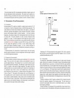
is through the retinacular artery, which ends as the
lateral epiphyseal artery (Berquist 1992) (Fig. 15.4).
Fig. 15.4. Vascular supply to the femoral head
Additional blood supply to the femoral head included
the medial retinacular artery which is a branch of
the inferior retinacular artery, and the foveal artery.
Poor contact, unstable reduction, and disruption of
the retinacular arteries are the most prominent factors leading to avascular necrosis (Berquist 1992),
which typically presents 9–12 months following the
fracture, but can present as early as 3 months or as
late as 3 years following the fracture (Fig. 15.5). In
younger populations, there is a higher incidence of
avascular necrosis and nonunion with Took and
Favero (1985) reporting an incidence of 33% and
5.5% nonunion of nondisplaced intracapsular fractures (Verattas et al. 2002). Swiontkowski et
al. (1984), in a series of 27 displaced intracapsular
femoral fractures, also reported a 20% incidence
of avascular necrosis with no nonunions. Prompt
reduction appears to have an effect as all cases in
Swiontkowski et al.’s 1984 study were reduced
within 12 h. Gautam et al. (1998) also reported that
emergent open reduction and screw fixation in 25
patients revealed only one nonunion at 32 months.
Treatment variables play a key role in achieving
good outcome with proximal femoral fractures.
Accurate reduction and stable fixation are prerequisites for satisfactory union. Tissue variables also
play a role in the success of treatment of intracapsular hip fractures. Many fractures are associated with
osteoporosis. Adequate reduction is often difficult
with significant deficiencies in bone mineralization
contributing to nonunion. It has also been found
that patients with abnormal bone such as Paget’s
disease have up to a 75% risk of nonunion (Dove
1980) prompting treatment with prosthetic replacement in these patients. This has also been reported
to be a concern in patients with fibrous dysplasia and
Bony Trauma 2: Proximal Femur
241
free vascularized or nonvascularized fibular grafts
may also utilized (Hou et al. 1993; Nagi et al. 1998).
Treatment of nonunion with total hip arthroplasty
typically represents the best option in older patients
with low functional demands and in complicated
cases, although studies have shown a slightly higher
failure rate with arthroplasty following nonunion
for hip fracture as opposed to those for osteoarthritis (Franzen et al. 1990; Skeide et al. 1996). It is
generally accepted that hip arthroplasty should be
reserved for older patients, noncompliant patients,
and for patients with significant preexisting acetabular disease (Rodriguez-Marchan 2003).
15.3
Extracapsular
Fig. 15.5. A 49-year-old patient status post fall with closed
reduction and internal fixation of a left femoral neck fracture
2 years previously with subsequent development of vascular
necrosis and collapse of the articular surface of the femoral
head
osteopetrosis (Steinwalter et al. 1995; Tsuchiya
et al. 1995).
Imaging can be helpful in evaluating for nonunion. With conventional radiographs, a change in
fracture or screw position, backing out of screws, or
penetration of the femoral head by a screw suggest
unstable internal reduction and nonunion. Recent
advances in CT allow precise visualization of the
hardware and surrounding bone with very little
metallic artifact and can be quite helpful in equivocal cases or in preoperative planning when revision
is needed.
In cases of nonunion several options are available for achieving union and the decision must
be tailored to the individual patient. Prosthetic
replacement is the most obvious option but in cases
in which prosthesis replacement is deemed unsuitable there are many femoral head sparing options
for achieving union of the fracture (Jackson and
Learmonth 2002). Several procedures including vascularized fibular grafting, additional compression fixation, and femoral neck osteotomy
augmented by muscle pedicle grafting are options
(Jackson and Learmonth 2002). Simple removal
of the cancellous screws with larger screws may be
successful in uncomplicated cases with no significant malalignment of foreshortening. Dynamic hip
screws may also be considered especially in cases of
foreshortening (Wu et al. 1999). Bone grafting with
15.3.1
Classification
Extracapsular fractures are those fractures occurring below the hip joint involving the trochanters
and the subtrochanteric femur and fittingly can be
divided into intertrochanteric fractures and subtrochanteric fractures. Avulsion fractures of the greater
and lesser trochanters can also occur and represent
a third category of extracapsular proximal femoral
fractures.
15.3.2
Intertrochanteric Fractures
Fracture lines occur with variable obliquities but
typically extend between the greater and lesser
trochanters. Comminution with detachment of the
greater and lesser trochanters are common (Maniscalo et al. 2002). Intertrochanteric fractures are
most commonly the result of a fall. The musculature
about the hip plays a role in the fracture morphology. The external rotators of the hip tend to remain
with the proximal fragment while the internal rotators tend to remain attached to the distal fracture
fragment (Berquist 1992).
Various classification schemes have been suggested based on location, angulation, fracture plane,
and degree of displacement. Delee (1984) classified
fractures as stable or unstable with fractures considered stable if, when reduced, there was adequate cortical contact medially and posteriorly at the fracture
site, the medial cortex of the femur was not commi-