Nghiên cứu xây dựng hệ thống kích thích tế bào thần kinh và ứng dụng trong đánh giá đáp ứng không gian của tế bào vị trí hồi hải mã tt tiếng anbh
Bạn đang xem bản rút gọn của tài liệu. Xem và tải ngay bản đầy đủ của tài liệu tại đây (2.44 MB, 27 trang )
MINISTRY OF EDUCATION AND TRAINING
MINISTRY OF NATIONAL DEFENCE
ACADEMY OF MILITARY SCIENCE AND TECHNOLOGY
TA QUOC GIAP
RESEARCH ON ESTABLISHING
THE NEURAL STIMULATION SYSTEM AND
APPLY FOR EVALUATING THE SPATIAL RESPONSE
OF HIPPOCAMPAL PLACE CELLS
Specialization: Electronic engineering
Code: 9 52 02 03
The abstract of dissertation
Hanoi – 2019
This dissertation was completed at:
ACADEMY OF MILITARY SCIENCE AND TECHNOLOGY
Scientific supervisors:
1. Dr. Nguyen Le Chien
2. Dr. Le Ky Bien
Reviewer 1: Tran Duc Tan, Ph.D., Assoc.Prof.
Reviewer 2: Nguyen Minh Phuong, Ph.D., Assoc.Prof.
Reviewer 3: Le Manh Hai, Ph.D.
The doctoral thesis was examined by the Doctoral Evaluating Council
of Academy level held at Military Science and Technology at … on …,
….
This thesis can be found at:
1. The library of Academy of Military Science and Technology
2. Vietnam National Library
1
INTRODUCTION
1. The necessity of the project
Biomedical engineering is an applied science field, which connects
different sciences from physics, chemistry, and biology to electrical,
control, information, micro and nano technologies in order to provide
biomedical solutions for improving human health. Neural engineering is
an important subfield of biomedical engineering, which uses engineering
techniques to treat, replace, or restore the functions of the neural system.
It requires a device possessed controllable and stable properties for
studying the mechanism of memory storing in the brain. This plays an
important role in a comprehensive understanding of physiological neural
system. Therefore, the development of systems that allow studying the
physiology of the nervous system has highly practical applications.
In this dissertation, a neural stimulation and recording sytem is
developed for evaluating behavioral and spatial responses of mice from
electrical stimulations with proper algorithms. This system allows deeper
understanding of the working principles of neurons and the brain. In
addtion, this is fundamental to study the structure and function of
hippocampus, which may be associated with some neurodegenerative
diseases such as Alzheimer’s, Amnesia, and Schizophrenia. The practical
exercises with their respective algorithms are first built on animals in
order to develop the electrical stimulating and recording system for
neurons. The built stimulation system allows evaluating the electrical
activity of neurons in their surrounding environment and the whole living
organism correlations. The electrical recording of neurons in
hippocampus is fundamental to assess cells’ behavior in this place.
Importantly, specific working principles of the central nervous system
will be elucidated to better understand feeling, memory, and autonomic
nervous mechanisms. Therefore, the project “research on essurrtablishing
the neural stimulation system and apply for evaluating the spatial response
on hippocampal place cells” has a practical role in comprehensive studies of
neuronal physiology.
2. Research objectives
2
- Developing a system for stimulating and recording the electrical activity
of neurons based on electronics engineering.
- Building mathematical algorithms of neuronal stimulation for 4
practical exercises on mice.
3. Research subjects and scope
- Research subjects: Neurons in a defined place of the Hippocampus is
electrically stimulated and recorded by using the built system. Supporting
devices and integrated programs for stimulating and recording are
synchronous to form a complete system. The stimulating and recording
processes are automatically performed and analyzed.
- Research scope: Developing a system that allows stimulating and
recording neurons. The stimulating programs associated with
mathematical algorithms are integrated into the system. Simulation and
analyzing the results are based on electronic engineering.
4. Research Methodology
Data collecting programs, simulations, and practical exercises are used
on mice for evaluating the system and exercises.
5. Research contents and thesis structure
The main research contents:
- The overview of the electrical activity of neurons
- Modeling neurons with equivalent circuits and building algorithms of
electrical simulations for neurons
- Evaluating the algorithms and system by simulation programs and
practical exercises on mice.
6. Scientific and practical significance
- Proposing proper stimulating parameters for studying subjects.
- Developing a system for stimulating and recording the electrical activity
of neurons with 4 algorithms and 4 practical exercises on animals.
- Performing simulations and practical exercises on mice to evaluate the
proposed system and programs
- Providing fundamentals of medical issues for studying the central
nervous system.
3
CHAPTER 1: THE OVERVIEW OF THE ELECTRICAL
ACTIVITY OF NEURONS
1.1. Membrane potential of neurons
Neurons are analogous to other cells, which have structural components
of cell membranes, nuclei and organelles. The electrical activity of
normal cells as well as neurons is highly related to the structure and
characteristics of the cell membrane.
1.2. Electrical nerve stimulation and medical significance
The development of nerve stimulating and recording system with proper
algorithms is based on studying electrical properties of the cell
membrane, the influence of electrical stimulating parameters, the
response of cell membranes, and electrical stimulations in medical
research.
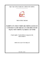
Figure 1.1. The change in membrane potential by the influence of
stimulating pulses.
1.3. The response of cell membrane to the electrical stimulation
The plasma membrane potential changes when neurons are stimulated.
The membrane potential will return to its initial resting value after
responding to the stimulus. If the electrical stimulation is insufficient to
create a transmembrane potential larger than a threshold, the membrane
4
will not be activated. The amplitude and frequency of the electrical
stimulation mainly influence the intracranial electrical stimulation, which
are used to determine the stimulating threshold and maximum response
of cells. In this work, electrical stimulating pulses are positive pulses with
their variable amplitudes and frequencies.
1.4. The recording methods of the neuronal action potential
The neuronal potential recording technique was developed in the 1940s.
During this period, extracellular microelectrodes were used to determine
the potential characteristics of a neuron. Recent studies of neurons
associated with the neural stimulation and response have proven the
relation of neurons in different places within brain. Current technologies
and equipment have also been developed for more accurate and
convenient analyses of neuronal activities.
1.5. Hippocampus and hippocampal place cells
Neuron studies have proven that hippocampal place cells play a vital role
in information store, short-term to long-term memory conversion and
spatial orientation.
1.6. The basic electronic circuit of neurons
To more comprehensively study and understand the action potential of
cell membrane on electric stimulation, an equivalent conducting model of
neurons has been modeled as an electronic circuit.
1.7. Relevant research
- National: currently, there is not any neuronal stimulating system, which
allows both stimulating and recording the electrical activity of neurons.
- Global: systems of manual neuronal stimulation and recording have
been often found, however most of them are not synchronized and
complete systems, which leads to the lack of accuracy in data analysis.
Some advanced systems can only describe the system function and
stimulation results, but not evaluate the system.
1.8. Chapter conclusion
5
CHAPTER 2: THE EQUIVALENT ELECTRICAL CIRCUITS OF
NEURONS AND ALGORITHMS FOR ELECTRICAL NEURAL
STIMULATION.
2.1. The electronic circuit of neuron membrane and the investigation
of electrical stimulating parameters
The action potential of cell membrane can be analogously
modelled as an electronic circuit.
2.1.2. The simulation of electrical stimulating parameters with the
Maeda-Makino model
XSC1
XFG2
SC1
Ext Trig
+
COM
_
IO1
IO3
IO2
B
A
+
R2
200Ω
PWM
I1
_
+
_
R8
100kΩ
C1
0.5µF
R1
100kΩ
Q3
2N3904
Q1
2N3904
0.07mA
R3
100kΩ
R5
10kΩ
R6
300Ω
Q2
2N3906
Q4
2N3904
R4
1kΩ
V1
5V
Q5
2N3904
XMM1
C4
0.2µF
C3
1µF
V2
0.4V
Figure 2.3. The electronic circuit model of neurons by Maeda and Makino.
2.1.3. Simulation results and discussions
The amplitude and frequency parameters of stimulation pulses are
applied to the electric circuit for simulating the action membrane potential
based on the Maeda – Makino model by the NI Multisim 14.0 progam.
2.1.3.1. The relationship between current and the membrane potential of
stimulation pulses at a fixed 80Hz frequency
The simulation results show that the membrane potential is directly
proportional to the stimulating intensity (Figure 2.6). However, the
potential only dramatically rises over the current of less than about 10μA
(the "bursting" range of potential response) before gradually increasing
in the current range from 10 to 110 μA. In addition, while the stimulating
current increases 110 μA, the potential increases suddenly and oscillates.
6
Theoretically, this explains the risk of breakdown voltage of electronic
components and the demolition of cell membrane.
Figure 2.6. The change of potential depends on the stimulating intensity at the
frequency of 80Hz.
2.1.3.2. The membrane potential depends on the frequency of stimulating
current at a fixed current.
Figure 2.7 shows the dependence of the membrane potential over
the frequencies of current from 0 to 180 Hz when the current intensity is
fixed. It can be seen that the membrane potential increases and reaches a
maximum value at the frequency of 100 Hz before slightly reducing at
higher frequencies.
Figure 2.7. The change of potential depends on the stimulating frequency at a
fixed intensity of 70μA.
7
2.2. The stimulation and recording system for electrical activity of
neurons
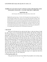
Figure 2.8. The illustration of the stimulation and recording system for
electrical activity of neurons
- The behavioral observation system: Consisting of a CCD camera for
monitoring movements, behavior and positions of mice
- The stimulation system: a pulse generator establishes the form and
parameters of pulses (Stimulator), which are sent to the isolator and DAC
via USB 6501 before delivering to the nerve cells of mice by stimulation
electrodes.
-The recording system: The neuronal membrane potential is also
recorded by stimulating electrodes. The recorded signal from neurons is
doubly amplified and processed by a signal processing unit (Plexon). The
action potential is recorded and synchronously counted together with the
stimulation pulse as well as the co-ordinates of the mice by control signals
(TTL form) from the processing program installed in the computer to the
Plexon system via USB device 6501.
The developed system with integrated programs forms a complete
device, which allows both electrically stimulating neurons and recording
the neuronal membrane potential with designed task algorithms.
8
2.3. Algorithms of electrical stimulations for neurons
2.3.1.1. The model of electrical stimulations for neurons with the NPT task
Processing
Circuit
Isolator
Stimulator
Monitor
USB
6501
Central
processing
system
Stimulating
electrode
Sensor
Mice
Figure 2.10. The model of electrical stimulations and nose – poking responses.
The input is the nose-poking behavior of the mice, which is
transmitted via an optical sensor hiddenly located in a circular hole with
the size diameter of 1.5 cm inside the chamber. The sensor operating
mode is set at a high logic status. When the nose-poking happens, the
sensor will be switched to a lower logic level. The response signal from
the sensor is sent to a processing circuit for counting the number of nosepoking if conditions of the task are completed as described in model 2.10.
2.3.1.2. The electrical stimulations for neurons with NPT task
a) The significance of the NPT exercise
The NPT task algorithm is based on the strict requirements of
reward conditions. The intensity and frequency parameters of electrical
stimulating pulses are evaluated from practical tasks in order to compare
with the simulated parameters. The NPT stimulation algorithm is shown
in Figure 2.11 with variable intensity and frequency parameters. The
program completely monitors the reward conditions and automatically
rewards when the conditions of the task are reached. The number of
rewards or nose-poking behaviour is updated and visually displayed on a
bar graph. These values are stored in a file and objectively analyzed to
evaluate the most appropriate parameters for spatial response tasks. The
expectation of the NPT task is to find the optimal parameters of the
stimulating electrical pulse, which makes mice interest and poking the
most in a period time of the task.
9
b) The NPT task
c) The algorithm flowchart
Start
Pt = 0; maxPt; chammui = 0; t = 0; maxT;
ptDelta = 0; tDelta = 0; delta;
countInterval = 0; interval
Chammui
Reading data
t++; delta++;
no
chammui =1
yes
chammui = 0; pt++; ptDelta++
no
tDelta = delta
yes
lưu ptDelta; ptDelta = 0; tDelta = 0
no
t == interval*(countInterval + 1)
yes
Pt == maxPt
|| t== maxT
no
countInterval++
yes
End
Figure 2.11. Algorithm flowchart for the NPT task.
2.3.2. The electrical stimulation models and algorithms for neurons
with the spatial response task
2.3.2.1. The model of electrical stimulations for neurons with DMT task
Figure 2.12. The model for the DMT task.
10
2.3.2.2. The constructions of electrical stimulation algorithms for
neurons with the DMT task
a) The significance of the DMT exercise
The algorithm of the DMT task (Distance Movement Task) is based on
strict requirements of reward conditions. The movements of mice will be
trained from easy to difficult requirements by the experimental tasks for
asserting the optimal intensity and frequency parameters of the
stimulating electrical pulses. Those parameters were already determined
in the NPT task in the aforementioned part.
b) The DMT task
c) Algorithm flowchart for the DMT task
Start
Pt = 0; s = 0; t = 0; xt-1 =
x0; yt-1 = y0;
xt = x0; yt = y0;
maxpt; maxT; delta
t++;
xt-1 = xt; yt-1 = yt
Reading data
xt; yt
s+ = sqrt[(yt-yt-1)2 + (xt-xt-1)2]
s >= delta
no
yes
s=0
Pt++
Pt = maxPt
|| t = maxT
no
yes
End
Figure 2.13. The algorithm flowchart of stimulations for the DMT task.
11
2.3.2.3. The model of electrical stimulations for neurons with the RRPST
and PLT tasks.
Monitor
CCD camera
Isolator
Stimulator
USB
6501
Central
processing
system
Plexon
AMP
recording
electrode
Stimulating
electrode
Mice
Figure 2.14. system for stimulating and recording the electrical activity of
neurons on the mice
The algorithm of electrical stimulations for the RRPST task
a) The significance of the RRPST exercise
The algorithm of the RRPST task (Random Reward Place Search
Task) is based on the strict requirements of reward conditions. The
movement and reward motivation of mice are evaluated by the algorithm
of electrical stimulations for building the program and content of the
RRPST task. This experimental exercise will train the mice to move for
searching rewards, which appear randomly. The number of rewards or
moving distances will be simulated to display the tracking path of mice
and to update the reward number. The obtained results are stored in a file
and objectively analyzed for assessing the movements of mice in a
particular space.
b) The RRPST task
c) The algorithm flowchart of stimulations for the RRPST task
12
Start
Pt = 0; t= 0; xt =
x0; yt = y0; xzt = xz0; yzt = yz0; wz
deltaTime = 0; delayTime; maxwidth;
maxPt; maxT; taovungpt = false
t++; deltaTime++;
x t; y t
Reading data
yes
deltaTime>= delayTime
& taovungpt = true
xzt = rand(0,maxwidth)
yzt = rand(0,maxwidth)
no
delta = sqrt[(xt – xzt)2 + (yt – yzt)2 ]
delta <= wz
& taovungpt = false
no
yes
delta = 0
taovungpt = true
Pt++; deltaTime =0
Pt == maxPt
|| t == maxT
no
yes
End
Figure 2.15. The algorithm flowchart of stimulations for the RRPST task.
The algorithm of stimulations for the PLT task
a) The significance of the PLT exercise
The algorithms of the PLT task (Place Learning Task) is based on
strict requirements of reward conditions. The movements of mice for
searching fixed rewards will be trained by experimental exercises. In
addition, a program is built which can strictly monitor the reward
conditions and automatically reward when the conditions are reached.
The number of rewards or moving distances will be simulated to display
the tracking path of mice and update the reward number. The obtained
13
results are stored in a file and objectively analyzed for assessing the
movements of mice in a particular space.
b) The PLT task
c) The algorithm flowchart of stimulations for the PLT task
Start
Pt = 0; t = 0; xz1;
yz1; xz2; yz2; wz
vungphanthuong = 1; deltaTime = 0;
delayTime; maxPt; maxT; delta
t++; deltaTime++;
xt; yt
Reading data
no
vungphanthuong =1
yes
delta = sqrt[(xt - xz1)2 +(yt - yz1)2]
delta = sqrt[(xt - xz2)2 +(yt - yz2)2]
no
no
delta <= wz
& deltaTime => delayTime
yes
yes
delta = 0;
deltaTime =0
Pt++;
vungphanthuong = 2
no
delta <= wz
& deltaTime => delayTime
delta = 0;
deltaTime =0
Pt++;
vungphanthuong = 1
Pt == maxPt
|| t== maxT
yes
End
Figure 2.16. The algorithm flowchart of stimulations for the PLT task.
14
CHAPTER 3: EVALUATING THE STIMULATION
ALGORITHMS AND THE SYSTEM BY BEHAVIOURAL
RESPONSES AND PRACTICAL EXERCISES ON MICE
3.1. Materials and methods
Animals: male mice weighed 26 - 29g are obtained from the
Central Institute of Hygiene and Epidemiology.
Electrode Implantation: monopolar stimulating electrodes,
(100µm in diameter, stainless steel) are implanted into the medial
forebrain bundle on both sides of the posterior lateral hypothalamic area
for intracranial self-stimulation (anteroposterior, -2,3mm; mediolateral, ±
0,7 to 0,75mm; and dorsoventral, -5,3 to 5,4mm).
The recording electrodes consist of 8 single electrodes, which can
be implanted into the CA1 area of the Hippocampus (region (2,1mm
posterior to Bregma, 1,8 mm lateral to Bregma, and 1,4mm below the
skull surface). The recording electrodes are checked before implanting.
The electrodes are gold plated to ensure a low contact resistance of 100 –
300 kΩ at 1kHz frequency.
Three screws (1,2 × 3mm, Matsumoto Industry Co., Ltd., Japan) are
also attached to the animal skull for making a reference electrode and
reinforcing the implanted electrodes into the head of the mouse. (Figure 3.1).
Figure 3.1. The illustration show the implanted stimulating and
recording electrodes
Research facilities:
The task for recording the nose - poking behaviors response
15
Figure 3.2. The recording chamber for the ICSS response and nose-poking
behaviors of mice.
Spatial tasks and memorability
Suitable parameters for performing the spatial response exercises
are determined by studying the ICSS response and nose-poking behaviors
of mice.
Figure 3.3. The illustration of the model and arrangement of the spatial tasks.
The spatial behavior of mice is investigated in an open round box
of 80 cm in diameter and 25 cm in height (figure 3.3).
3.2. Simulation results
From the built algorithms of 4 practical exercises (NPT, DMT,
RRPST, and PLT) in chapter 2, the stimulation and recording programs
for the electrical activity of neurons with 4 respective practical exercises
on mice as shown in Figure 3.4.
16
3.2.1. Simulation of the NPT exercise
Figure 3.4. The progam for simulating and recording
of nose-poking response.
Recorded data is stored and analyzed to evaluate the response of
mice to the intensity and frequency of the stimulating current.
3.3. Analysis and evaluation of practical results on mice
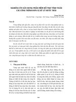
3.3.1. Practical results of the NPT exercise
The ICSS response of mice is recorded after implanting the electrode for
one week. During experiment, animals are kept inside a cage with a 1.5
cm hole at the middle and an optical sensor at the bottom (Omron EESPX303). Each time the mice poke their nose to the hole, a serial of
stimulating pulses for 0,5s is activated (each is a 0,3ms negative square
Cathode pulse)
It can be seen from Figure 3.8 that, the recorded curve is consistent with
the Gompertz model. It is also suitable to the response trend of electrical
circuit model of neurons for the stimulation parameters evaluated by
simulations in chapter 2.
* The intensity of stimulation
It can be seen from the Figure 3.8 that the average number of nosepoking behaviors in a minute depends on the intensities of the stimulating
current (the blue lozenge dots) as compared to calculated values (the
17
orange square dots) by the Gompertz model. The experiments are
performed on 7 mice (each mouse is repeated 2 twice in 2 days). The
variation shown in graph is SE (standard error) for the statistical analysis
of experiments.
Figure 3.8. The dependence of nose-poking response on
the stimulating intensity
*The Stimulating frequency
Figure 3.9. The dependence of nose-poking response on the stimulating
frequency.
From the Figure 3.9, the average number of nose-poking behaviors
in a minute depends on the frequencies of the stimulating current (the blue
18
lozenge dots) as compared to the calculated values (the orange square
dots) by the Gompertz model. The experiments are performed on 6 mice
(each mouse is repeated in two different days). The variation shown in
graph is SE (standard error) for the statistical analysis of experiments.
3.3.2. Experimental results for the spatial response tasks
Figure 3.10. Results in the spatial response tasks
3.4. The results of stimulating and recording experiments of the
neuronal electronic activity in the Hippocampus on mice
The depth of the recording electrodes is increased by 20 µm per
day during the measurements.
* The general characteristics of the Hippocampal place cells
Figure 3.11. The neuron activity are recorded and isolated using an offlinesorter program (Plexon).
19
3.5. The evaluation of the algorithms, stimulation and recording
systems for the electrical activity of neurons.
3.5.1. The evaluation of algorithms
This research proposes 4 exercises with 4 respective algorithms for
studying the electrical activity of neurons on mice. The algorithms were
strictly based on the requirements of specific conditions in order to ensure
to train the mice from easy to difficult tasks. The processing and
controlling programs were then built by using these algorithms.
3.5.2. The evaluation of the stimulating and recording system for the
electrical activity of neurons.
* The stability and accuracy of the system:
The system will offer a reward (100% efficiency) to the mouse
when the reward conditions are reached during each measurement for 4
exercises. The recording system regularly monitors the electrical activity
of neurons to ensure a complete evaluation in correlation with the
stimulation. Moreover, the recording system has sensitivity of an mV
range, which can run stably and errorlessly.
*The delay of system
+ The NPT task
Processing
circuit
Isolator
Stimulator
Monitor
USB
6501
Central
processing
system
Stimulating
electrode
Sensor
t1
Labchart v8.1.8
t2
Figure 3.13. The evaluation of the stability and delay of the system
for the NPT task by the Labchart Pro v8.1.8.
The delay of the NPT system: 𝛥𝑡𝑁𝑃𝑇 is a period when the mouse
has its nose-poking behaviour until it receives the stimulating signal. The
𝛥𝑡𝑁𝑃𝑇 is determined by 60 ms while a period for receiving a reward is
20
0.74 s. It is clearly noticed that the 𝛥𝑡𝑁𝑃𝑇 is much smaller than the period
of one reward acquisition.
Figure 3.14. The illustration for pulses of the reward condition, reward
delivery, and the delay time of the system.
+ The DMT, RRPST and PLT tasks:
The stability and delay evaluation of the system for The DMT,
RRPST and PLT tasks are described in Figure 3.15. The t1 is time when
the reward conditions are reached, which is determined by: the movement
time of mice in a defined distance (the DMT task); the touch of mice on
random reward areas (the RRPST task); the touch of mice on defined
reward areas (red and green) with successive conditions (the PLT task).
The t2 is the time when mice receive the reward.
monitor
t1
CCD camera
Isolator
Stimulator
USB
6501
t2
Central
processing
system
Stimulating
electrode
Figure 3.15. The evaluation of the stability and delay of the system for the
DMT, RRPST and PLT tasks.
21
The simulation program for evaluating the delay time of the DMT,
RRPST and PLT tasks.
Figure 3.16. The program for evaluating the stability and delay time of the
DMT task.
Figure 3.16. The program for evaluating the stability and delay time of the
RRPST task.
22
Figure 3.20. The program for evaluating the stability and delay time
of the PLT task.
The delay time between t1 and t2 averagely calculated for the DMT,
RRPST, and PLT tasks are 4,88 ± 2,01ms; 4,44 ± 1,91ms and 4,91 ±
2,12ms respectively. Thus the maximum movement of mice during the
average delay time for all three tasks is:
7,03 × 0,083 0,58 mm 200 mm (the diameter of the reward area)
Moreover, the delay time is statistically estimated from 3 to 7ms in
1500 measurements for all three tasks of the DMT, RRPST, and PLT.
There is only one delay time of 24,28ms when the maximum movement
of mice is 2,02mm (24,28 × 0,083) 200mm, the radius of the reward
area. This means during the delay time for all tasks (DMT, RRPST and
PLT), mice almost do not move out of their current place. Therefore, it
can be assumed that the delay time of the system is equal to zero (mice
receive the reward immediately when the reward conditions are reached).
23
CONCLUSION
In the scope of this thesis, a neural stimulation system has been
established to evaluate the spatial response of the Hippocampal place
cells by practical experiments. The main results obtained in this project
are summarized by these following contributions:
1. Results
The electrical activity of neurons has been overviewed in the first
part of this thesis, which focuses on the electrical stimulation of nerve
cells. The equivalent circuit model of neurons is also presented for better
understanding the influence of stimulation parameters on the neuronal
electrical activity. The Maeda-Mekino model has been used to study the
intensity and frequency of the stimulating current by the NI Multisim
simulation program, version 14.0.
To evaluate the influence of the intensity and frequency of the
stimulation on the electrical activity of neurons, both simulation and
practical experiments on animals have been performed in this research.
The studies of nose poking behavior of mice associated with the
stimulation parameters allow selecting the optimal stimulation values: An
intensity of 100 µA and a frequency of 100 Hz. Proper stimulation
parameters (80% optimal values) were used to study the Hippocampal
place cells for three spatial exercises.
The stimulation parameters, behavioral response, mobilization,
learning and memorizing abilities of animals were investigated by 4
practical exercises with their respective algorithms. These exercises with
the suitable algorithms are integrated into a stimulation system for
electrically stimulating the cells. Moreover, a recording system has been
proposed in this project for recording neurons at the Hippocampus. The
stimulation and recording fuctions are both synchronized into a complete
system, which allows evaluating the electrical activity of neurons.