Formation tracking control of ocean vehicles
Bạn đang xem bản rút gọn của tài liệu. Xem và tải ngay bản đầy đủ của tài liệu tại đây (674.47 KB, 10 trang )
ISSN: 1859-2171
TNU Journal of Science and Technology
192(16): 87 - 96
FORMATION TRACKING CONTROL OF OCEAN VEHICLES
Dang-Binh Nguyen1,*, Khac-Duc Do2, Van-Vi Nguyen1, Van-Hung Nguyen1
1
Viet Bac University, 1B street, Dongbam ward;
2
Curtin University, Autralia;
ABSTRACT
We present an application of our constructive method for design cooperative controllers in (KhacDuc Do et al., 2018) to solve the problem of forcing a group of N ocean vehicles under
environmental disturbances to track desired paths in a horizontal plane. The reader is referred to
(Khac-Duc Do et al., 2018) for a survey of the formation control field.
Keywords: Formation tracking control, ocean vehicles.
Received: 12/11/2018;Revised: 21/11/2018; Approved: 28/12/2018
ĐIỀU KHIỂN BÁM NHÓM CÁC PHƯƠNG TIỆN GIAO THÔNG ĐƯỜNG BIỂN
Nguyễn Đăng Bình1, Đỗ Khắc Đức2, Nguyễn Văn Vị1, Nguyễn Văn Hùng1
1
Trường Đại học Việt Bắc, Thành phố Thái Nguyên.
2
Đại học Curtin, Úc
TÓM TẮT
Trình bày một ứng dụng lý thuyết điều khiển nhóm trong (Khac-Duc Do và cộng sự, 2019) vào
việc thiết kế các bộ điều khiển nhóm bám trong mặt phẳng nằm ngang cho một nhóm N phương
tiện đường biển chịu tác động của môi trường biển. Người đọc tham khảo (Khac-Du Do và cộng
sự, 2019) để khảo sát về lý thuyết thiết kế điều khiển hợp tác.
Từ khóa: Điều khiển nhóm, các phương tiện giao thông đường biển.
Ngày nhận bài: 12/11/2018; Hoàn thiện: 21/11/2018; Duyệt dăng: 28/12/2018
(*) Corresponding author: Tel:0913 286661, Email:
; Email:
87
Nguyen Dang Binh et al.
TNU Journal of Science and Technology
192(16): 87 - 96
MATHEMATICAL MODEL AND CONTROL OBJECTIVE
The equations of motion of the i th ocean vehicle such as surface ships and underwater vehicles
moving in a horizontal plane (for clarity roll, pitch and heave motions are ignored) can be written
as 0:
i = J ( i )i
M ii = -Ci (i )i - ( Di + Din (i ))i + i + J T ( i )bi
(1)
with i [ xi yi i ]T , i [ui vi ri ]T , i [ ui vi ri ]T , bi [bui bvi bri ]T ,
cos( i ) sin( i )
J ( i ) sin( i ) cos( i )
0
0
0
0
0
mi11 0
0 0 Ci13
Di11 0
0 , M i 0 mi 22 mi 23 , Ci (i ) 0 0 Ci 23 , Di Din (i ) 0 Di 22 Di 23
0 m m
C C
0 D D
1
i 32
i 33
i 32
i 33
i 31 i 32 0
(2)
where
mi11 mi X iu , mi 22 mi Yiv , mi 23 mi xig Yir , mi 32 mi xig N iv , mi 33 I iz N ir ,
Ci13 Ci 31 mi 22vi 0.5(mi 23 mi 32 )ri , Ci 23 Ci 32 mi11ui , Di11 ( X iu X i u u ui ),
(3)
Di 22 (Yiv Yi v v vi Yi r v ri ), Di 23 (Yir Yi v r vi ), Di 32 ( N iv N i v v vi N i r v ri ),
Di 33 ( N ir N i v r vi N i r r ri )
where
xi , yi
are the surge and sway
displacements, i is the yaw angle with
in the earth fixed frame;
ui , vi and ri denote surge, sway and yaw
Yib
X ib
Y
v
coordinates
Oib
yi
Oic
velocities with coordinates in the body-fixed
frame; mi is the mass of the ship; I iz is the
i
xig
ship’s inertia about the Z ib -axis of the bodyfixed frame; xig is the X ib -coordinate of the
O
xi
X
ship center of gravity, O ic , in the body-fixed
Figure 1. Vessel coordinates
frame (see Figure 1); the controls
iu , iv and ir are the surge and sway forces
Since collision is related to the position
( xi , yi ) of the vessel, we decouple the model
(1) into the “position” and “orientation”
models as follows
and yaw moment in the body-fixed frame;
biu , biv and bir are the constant disturbance
forces and moment acting on surge, sway and
yaw axes. The other symbols are referred to
as hydrodynamic derivatives 0. For example,
the hydrodynamic added mass force Yi along
the y i -axis due to an acceleration ui in the
xi -direction is written as Yi Yiuui with
Yiu : Yi / ui . We assume that all the ship
parameters and disturbances are unknown but
constant.
88
qi i
ui ui b
i vi vi i
i ri
ri ri ri bi
(4)
where
x
cos( i ) sin( i ) ui
qi i , i
yi
sin( i ) cos( i ) vi
and we have chosen the control i as
(5)
i Ci (i )i ( Di + Din (i )i M i J 1 ( i ) J ( i )i [ ui vi ri ]T
(6)
; Email:
Nguyen Dang Binh et al.
TNU Journal of Science and Technology
where ui , vi and ri are new controls to be
designed; ui , vi and ri are the first,
second and third rows of J ( i ) M i-1 J T ( i ) ,
i.e.
ui
vi ri J ( i ) M i-1 J T ( i ) .
T
(7)
In this section, we consider the problem of
designing the control input i or ( ui , vi , ri )
for each vehicle i that forces the group of N
vehicles whose dynamics are given in (1) or
(4) to track a moving changeable desired
formation graph in the sense that the desired
formation graph is allowed to move on a
desired trajectory Γod , and is allowed to
change its shape including rotation,
contraction and expansion, see Figure 2. The
group of N vessels needs N individual
reference trajectories. The desired formation
is achieved by forcing each vessel to track its
reference trajectory. We consider the
formation graph whose center O moves
along a reference trajectory Γ od ( s ) with s
being the path parameter. We assume that
Γ od ( s ) is regular in the sense that it is single
valued and its first and second derivatives
exist and are bounded. Since the formation
graph
under
consideration
is
only
representative, the center does not have to be
the center of the graph but can be any
convenient point. The shape of the graph can
be varied by specifying the coordinates as a
function of m called the formation shape
parameter vector, from each vertex i to the
center of the graph. The parameter vector
is used to specify rotation, expansion and
contraction of the formation such that when
converges to its desired value f , the
desired shape of the formation is achieved.
When the graph moves along the trajectory
Γ od ( s ) , the vertex i generates the reference
trajectory qid (s,) for the agent i . Designing
the control input i or ( ui , vi , ri ) for each
agent i that directly forces the vessel i to
track its reference trajectory qid (s,) is
difficult except for the case where the
; Email:
192(16): 87 - 96
trajectory qid (s,) is a straight line due to
collision avoidance taken into account.
Therefore we consider the dynamics of the
vessels in the moving coordinate frame
attached to the graph and its origin coincides
with the center of the graph.
Moving frame
Y
Vessel i
Y
vi
X
yi
yi
xi
O
yod
qid
Γod
O
Formation graph
xod
X
xi
Figure 2. Formation coordinates in 2D.
The control objective is formally stated as
follows:
Control objective: Assume that at the initial
time t0 each vessel starts from a different
location, and that each vessel has a different
desired location on its reference trajectory
qid (s,) , i.e. there exists a strictly positive
constant dij , which is referred to as the
minimum safe distance between the vessel i
and the vessel j , such that
|| qi (t0 ) q j (t0 ) || d ij
(8)
|| qid q jd || d ij , i, j {1,2,... N }.
Design the control input ( ui , vi , ri ) for each
vessel i and an update law for the unknown
disturbance vector bi , and the formation
vector such that position and yaw angle of
each vessel (almost) globally asymptotically
tracks its reference trajectory qid (s,) and
id , while avoids collisions with all other
vessels in the group, i.e.
limt ( qi (t ) qid ) 0
limt ( i (t ) id ) 0
|| qi (t ) q j (t ) || d ij , i, j {1,2,... N }, t t0 0 (9)
limt ( (t ) f ) 0.
89
Nguyen Dang Binh et al.
TNU Journal of Science and Technology
192(16): 87 - 96
CONTROL DESIGN
As mentioned before, we now consider the dynamics of the agents in the moving coordinate
frame, OXY attached to the formation graph, see Figure 6. The origin O of this frame coincides
with the center of the graph, and is on the reference trajectory Γod ( xod ( s), yod ( s)) . The
OX and OY axes of this frame are tangential and perpendicular to the reference trajectory
Γod ( xod ( s), yod ( s)) . Therefore the angle between the OX and OX is calculated as
arctan( yd' / xd' ) , where ' / s . Let the coordinates and desired coordinates of the agent
i assigned to the vertex i of the formation graph in the moving frame OXY be qi ( xi , yi ) and
qid () ( xid (), yid ()) . Therefore, if we are able to design the control input ( ui , vi , ri ) for the
lim t ( qi (t ) qid ( )) 0,
lim t ( (t ) f ) 0,
agent i such that
(10)
|| qi (t ) qi (t ) || d ij ,
lim t ( i (t ) id ) 0, t t0 0
where id is the desired yaw angle of the vessel i , and let the moving frame OXY moves along
the trajectory Γod ( xod ( s), yod ( s)) , then the control objective is solved. A simple choice of the
desired angle is id . This choice implies that we want the yaw angle i of all vessels to
approach the same value arctan( yd' / xd' ) . From Figure 6, we have
qi R( )(qi qod )
(11)
where qod [ xod yod ] and R ( ) is the rotation matrix given by
T
cos( )
R ( )
sin( )
sin( )
.
cos( )
It is noted that R ( ) is indeed invertible for all
the solutions of (4) gives
(12)
. Differentiating both sides of (11) along
qi i
ui ui
R
(
)(
q
q
)
2
R
(
)(
q
)
R
(
)
b
q
i
i
od
i
od
i
od
vi vi
i ri
ri ri ri bi
(13)
where i R( )( i qod ) R( )(qi qod ) . Since the system (13) is of a strict feedback form,
we will use the backstepping technique and the technique developed in the previous section to
design the control ( ui , vi , ri ) to achieve the control objective. The control design consists of
two steps as follows.
Step 1. At this step, we consider i and ri as controls. Define
i i
ri ri r
i
(14)
i
where i and ri are virtual controls of i and ri , respectively. In order to design i and ri ,
we consider the following potential function:
i i i 0.5 ie2 0.5 || f ||2
90
(15)
; Email:
Nguyen Dang Binh et al.
TNU Journal of Science and Technology
192(16): 87 - 96
where is a positive tuning constant, and ie i id . The functions i and i are the goal
and related collision avoidance functions specified as follows (see Subsection 3.2 for
motivation):
ijk
1
1
i || qi qid ||2 , i
(16)
2 k k
2
ij
jN i ijd
where Ni is the set of the agents which are adjacent to the agent i and
1
1
(17)
ij (|| qi q j ||2 dij2 ), ijd (|| qid q jd ||2 dij2 ) .
2
2
It is noted the yaw angle is not included in the collision avoidance function ij since it does not
contribute to collisions. Differentiating both sides of (15) along the solutions of (13) with the use
of (14), (16) and (17) gives
(18)
i Ti ( i i )
Tij ( j j ) ie ( ri ri id ) Ti ( f )T
jNi
1
1
ij k 2 k 2 k ijk 1 (qi q j )
ijd ij
where i qi qif
ij
jNi
ijk
q jd
q
T qid
i (qi qid )
2 k
(qid q jd )T id
2 k 1
jNi ijd
(19)
T
.
The equation (18) suggests that we choose the controls i and ri and the update as
i C i
ri i ie id
( f )
(20)
where C 22 and m m are symmetric positive definite matrices, and i is a positive
constant. Substituting (20) into (18) results in
2
T
i Ti Ci
Tij ( j j ) ie ri Ti ( f ) ( f )T ( f ) .(21)
i ie i i
jNi
qi Ci i
(22)
ie
i ie ri .
Step 2. At this step, we design the control i and an update law for the disturbance vector bi .
Consider the following function
(23)
i i 0.5 iT i ri 2 biT b1bi
Substituting (20) into the first two equations of (13) yields
i
where bi bi bˆi with bˆi an estimate of bi . Differentiating both sides of (23) the solutions of
(21) and the last equation of (13) results in
i Ti C i i ie2
Tij ( j j ) Ti ( f ) ( f )T ( f )
jNi
ui bˆ q
R( )(qi qod ) 2 R( )( i qod ) R( ) ui
od
i
i
i
vi
vi
ri ri ri bˆi ie ri iT R ( ) ui ri ri bˆiT bi1 bi
vi
T
i
; Email:
(24)
91
Nguyen Dang Binh et al.
TNU Journal of Science and Technology
192(16): 87 - 96
From (24), we choose the control i and an update law for the unknown parameter vector i as
follows:
ui ui bˆ q R 1 ( ) R ( )( q q ) 2 R ( )( q ) H
od
i
od
i
od
i
i
i i
vi
vi i
ri ri bˆi ie ri wi ri
(25)
T
bˆi bi iT R ( ) ui ri ri
vi
where Hi is a symmetric positive definite matrix, and wi is a positive constant. Substituting (25)
into (24) results in
2
T
2
i Ti Ci
Tij ( j j ) Ti ( f ) ( f )T ( f ) (26)
i ie i H i i wi ri
jNi
Indeed, substituting the control ( ui , vi , ri ) into the derivative of i and ri results in
ui b
i H i i
i
vi i
(27)
ri wi ri ie ri bi .
STABILITY ANALYSIS
We only show that with the control ( ui , vi , ri ) and the update law for the disturbance vector
given in (25), and the update law for formation parameter (20), there are no collisions between
agents, the solutions of the closed loop system consisting of (22), the third equations of (20) and
(25), and (27) exist, and limt i 0 . Proof of the critical point q qd with q [q1T ,..., qNT ]
T
and qd [q1Td ,..., qNd
] being the asymptotically stable, and other equilibrium points being unstable
or saddle follows the same lines as in Section 3. We consider the following function
(28)
tot log(1 ) 0.5( f )T ( f )
N
(i 0.5 i 0.5 ie2 0.5 iT i 0.5ri 2 0.5biT b1bi 0.5( f )T ( f ))
where
i
i 1
N
( i 0.5 i 0.5 0.5 i 0.5ri 0.5b b 0.5( f ) ( f ))
2
ie
i 1
T
i
2
T
i
1
bi i
(29)
T
which is proper using the same arguments as in Subsection 3.2. Differentiating both sides of (28)
along the solutions of (26) and the second equation of (20) satisfies
2
( f )T ( f )
1
i 1
i 1
.
(30)
From the expressions of and i , see (15), (16), (19) and (29), it can be checked that there
tot
1
1
N
(Ti C i i ie2 iT H i i wi ri 2 )
exists a positive constant max such that
1
1
N
||
i
1
1
N
|| max .
f )
T
i (
(31)
i 1
Using (31), we can write (30) as
2
max () N
|| i || max () || f ||2 min () || f ||2
(32)
2
4 (1 ) i 1
where is a positive constant, max () and min () denote the maximum and minimum
eigenvalues of . Picking min () / max () , we can write (32) as
tot
92
; Email:
Nguyen Dang Binh et al.
TNU Journal of Science and Technology
192(16): 87 - 96
2
max
( ) 2
max max .
4min
Integrating both sides of (33) from t0 to t results in tot (t ) tot (t0 ) max (t t0 )
From definition of tot we can write (34) as
tot
N
( (t ) 0.5 (t ) 0.5
i
i 1
i
2
ie
(33)
(34)
(t ) 0.5 iT (t ) i (t ) 0.5ri 2 ( t ) 0.5biT ( t ) bi1bi ( t ) 0.5( ( t ) f ) T ( (t ) f ))
N
( i (t0 ) 0.5 i (t0 ) 0.5 ie2 (t0 ) 0.5 iT (t0 ) i (t0 ) 0.5ri 2 (t0 ) 0.5biT ( t0 ) bi1bi ( t0 )
i 1
0.5( (t0 ) f )T ( (t0 ) f )) max (t t0 )
(35)
where
ijk (t )
1
1
2
2 k k , ij ( t ) || qi ( t ) q j ( t ) || ,
2
(
t
)
ijd
ij
jN i
(36)
k
ij (t0 )
1
1
1
2
2
i (t0 ) || qi (t0 ) qid || , i (t0 )
2 k k
, ij ( t0 ) || qi ( t0 ) q j (t0 ) || .
2
2
ij (t0 )
jN i ijd
i (t )
1
|| qi (t ) qid ||2 , i (t )
2
From (8) and (10) we have ij (t0 ) and ijd are strictly larger than some positive constants.
Therefore the right hand side of (35) cannot escape to infinity unless at the time t .
Therefore, the left hand side of (35) cannot escape to infinity for all t [t0 , ) . This implies that
ij (t ) cannot be equal to zero for all t [t0 , ) , i.e. no collisions can occur for all t [t0 , ) .
Since the left hand side of (35) cannot be escape to infinity in a finite time, qi (t ) cannot escape
to infinity in a finite time. This means that the solutions of the closed loop system consisting of
(22), the second equations of (20) and (25), and (27) exist. On the other hand, it is true from the
second equation of (20) that || (t ) f ) |||| (t0 ) f ) || e min ( )( t t0 )
(37)
which implies that the desired formation shape is exponentially achieved. Substituting (37) into
(30) yields tot max ( ) max || (t0 ) f || e min ( t t0 ) .
(38)
Integrating both sides of (38) from t0 to t gives
N
( (t ) 0.5 (t ) 0.5
i
i 1
i
2
ie
(t ) 0.5 iT (t ) i (t ) 0.5ri 2 ( t ) 0.5biT ( t ) bi1bi ( t ) 0.5( ( t ) f ) T ( (t ) f ))
N
( i (t0 ) 0.5 i (t0 ) 0.5 ie2 (t0 ) 0.5 iT (t0 ) i (t0 ) 0.5ri 2 (t0 ) 0.5biT ( t0 ) bi1bi ( t0 )
i 1
0.5( (t0 ) f )T ( (t0 ) f )) max ( ) max || (t0 ) f || / min .
(39)
The right hand side of (39) is bounded. Therefore the left hand side of (39) must also be bounded.
This implies that the third inequality of (10) holds. Since limt ( (t ) f ) 0 , applying
Barbalat’s lemma to (30) gives
N
1
lim t
(Ti (t )Ci (t ) i ie2 ( t ) 0.5 iT ( t ) i ( t ) 0.5ri 2 ( t )) 0
1 (t ) i 1
which implies that
2
T
2
limt Ti (t )Ci (t )
i ie (t ) 0.5 i (t ) i (t ) 0.5ri (t ) 0
limt (t ) 1
; Email:
(40)
(41)
93
Nguyen Dang Binh et al.
or
TNU Journal of Science and Technology
192(16): 87 - 96
2
T
2
limt Ti (t )Ci (t )
i ie (t ) 0.5 i (t ) i (t ) 0.5ri (t ) 2
limt (t )
where 1 and 2 are some constants. From
definitions of i and , the limit set (42)
cannot be true. Therefore, the limit set (41)
implies
that
limt || (i (t ), ie (t ), i (t ), ri (t )) || 0 .
Therefore, carrying out the same analysis as
in Section 3 yields the critical point q qd is
the asymptotically stable, and other
equilibrium points are unstable or saddle.
Furthermore, we can let the moving frame
OXY
move
along
the
trajectory
Γod ( xod ( s), yod ( s)) by letting qod move, i.e.
by giving s some desired value since
'
'
qod [ xod
( s) yod
( s)]T s . Finally, we note that
convergence of q to qd implies that of qi to
R( )1 qid qod qid , i.e. what we wanted to
achieve. We summarize the results of this
subsection in the following theorem.
Theorem 1. Under the assumptions stated in
the control objective (see (9)), the control
ˆ for unknown
i and the update law
i
parameters given in (25), and the update law
for formation parameter (20) each agent i
solves the control objective, i.e. (9) is
achieved.
(42)
(0,0)
ODIN 1
ODIN 3
ODIN 2
(r,-r)
(-r,-r)
ODIN 3
(0,-2r)
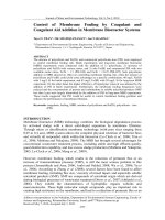
Figure 4. Desired formation graph.
SIMULATION RESULTS
We now illustrate the results stated in
Theorem 2 by a simulation on formation
tracking control for a fleet of 4 omnidirectional intelligent navigators (ODINs)
moving in a horizontal plane, see Figure 7.
The parameters of each ODIN are taken as
follows
mi11 mi 22 300, mi 33 16, X iu Yiv 168, Nir 10
. All other parameters defined in (3) are equal
to zero. The disturbance vector is taken as
bi 0.5[mi11 mi 22 mi 33 ]T . The safe distance
between any two ODINs is dij 0.8 ,
(i, j ) {1,2,3,4} . The control gains and
tuning
constants
are
chose
as
C diag(3,3), 0.1, k 1, wi 1, i 1,
bi diag(1,1,1) and the trajectory parameter
0.1
4
||qi qid ||
. For clarity,
s is updated with s e
we do not include the formation change in
simulations, i.e. the formation parameter is
not used. The desired formation shape is
specified
as
q1d [0, 0]T , q2d [r, r]T , q3d [0, 2r]T , q4d [r , r]T
with r 15 , see Figure 8. We carry out two
simulations. For the first simulation, the
initial
conditions
are
chosen
as
q1 (0) (0.7r,0), q2 (0) (0, 0.7r),
q3 (0) (0.7r,0), q4 (0) (0,0.7r) , and the
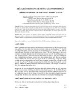
i 1
Figure 3. An outside view of an ODIN.
Courtesy
/>
94
; Email:
Nguyen Dang Binh et al.
TNU Journal of Science and Technology
192(16): 87 - 96
motion of ODINs in the (x,y) plane is plotted
in Figure 7. The controls 1 [ u1 v1 r1 ]T ,
qod [r sin( s) r cos( s)]T . A snap shot of
and the distances from ODIN 1 to all other
motion of ODINs in the (x,y) plane is plotted
ODINs || q1 qi ||, i 2,3,4 are plotted in
in Figure 5. For clarity, we only plot the
T
Figure 8. It is seen from these figures that all
controls 1 [ u1 v1 r1 ] , and the distances
ODINs nicely form the desired formation and
from ODIN 1 to all other ODINs
the desired formation graph moves on the
|| q1 qi ||, i 2,3,4 in Figure 6. For the
desired reference trajectory. It is also seen
second simulation, the initial conditions are
that these distances are greater than
chosen
as
2d , (i, j ) {1,2,3,4} , i.e. no collisions
q1 (0) (0, 1.7r), q2 (0) (0.7r, r), q3 (0) (0, 0.3r), qij4 (0) (0.7r, r)
between
the
ODINs
occur.
, and the reference trajectory qod is a straight
reference trajectory qod is a circle given by
line given by qod [s 0]T . A snap shot of
Figure 5. Circular reference trajectory: a snap shot of motion of ODINs in (x,y) plane.
Figure 6. Circular reference trajectory: Controls and distances from ODIN 1 to other ODINs
; Email:
95
Nguyen Dang Binh et al.
TNU Journal of Science and Technology
192(16): 87 - 96
Figure 7. Linear reference trajectory: a snap shot of motion of ODINs in (x,y) plane.
Figure 8. Linear reference trajectory: Controls and distances from ODIN 1 to other ODINs
REFERENCES
1. Fossen T.I. (2002). Marine control systems. Marine Cybernetics, Trondheim, Norway.
2. Khac-Duc Do, Dang-Binh Nguyen, Van-Vi Nguyen and Van-Hung Nguyen (2019). Formation
stabilization of mobile agents using local potential functions, TNU Journal of Science and Technology,
192(16), pp. 73-86.
96
; Email: