Free vibration analysis of sandwich beams with FG porous core and FGM faces resting on winkler elastic foundation by various shear deformation theories
Bạn đang xem bản rút gọn của tài liệu. Xem và tải ngay bản đầy đủ của tài liệu tại đây (415.5 KB, 11 trang )
Journal of Science and Technology in Civil Engineering NUCE 2018. 12 (3): 23–33
FREE VIBRATION ANALYSIS OF SANDWICH BEAMS
WITH FG POROUS CORE AND FGM FACES RESTING ON
WINKLER ELASTIC FOUNDATION BY VARIOUS SHEAR
DEFORMATION THEORIES
Dang Xuan Hunga,∗, Huong Quy Truonga
a
Faculty of Building and Industrial Construction, National University of Civil Engineering,
55 Giai Phong road, Hai Ba Trung district, Hanoi, Vietnam
Article history:
Received 02 March 2018, Revised 26 March 2018, Accepted 27 April 2018
Abstract
This paper studies the free vibration behavior of a sandwich beam resting on Winkler elastic foundation. The
sandwich beam is composed of two FGM face layers and a functionally graded (FG) porous core. A common
general form of different beam theories is proposed and the equations of motion are formulated using Hamilton’s principle. The result of the general form is validated against those of a particular case and shows a good
agreement. The effect of different parameters on the fundamental natural frequency of the sandwich beam is
investigated.
Keywords: sandwich beam; FGM; functionally graded porous core; free vibration; natural frequency.
c 2018 National University of Civil Engineering
1. Introduction
Functionally graded (FG) porous material is a novel FGM in which porous property is characterized by the FG distribution of internal pores in the microstructure. Beside the common advantages
of FGM materials, the FG porous materials also present excellent energy-absorbing capability. The
advantages of this material type led to the development of many FG sandwich structures that have
no interface problem as in the traditional laminated composites. These structures become even more
attractive due to the introduction of FGMs for the faces and porous materials for the core. However,
shear strength is always a disadvantage of this type of structures. Thus, a study of the effect of shear
deformation on their behavior is necessary.
Based on great advantages of FG sandwich structures, many researchers have paid their attention
to investigate mechanical behavior of these structures. Queheillalt et al. (2000) studied the creep
expansion of porous sandwich structure in the process of hot rolling and annealing. In this process, the
porous core of the sandwich material is produced by consolidating argon gas charged powder [1]. This
∗
Corresponding author. E-mail address: (Hung, D. X)
23
Hung, D. X., Truong, H. Q. / Journal of Science and Technology in Civil Engineering
porous core of the
sandwich
material
is /produced
by consolidating
argon
gas Engineering
charged powder [1]. This
Hung,
D. X., Truong,
H. Q.
Journal of Science
and Technology
in Civil
process was then simulated by the same authors in [2]. This idea was developed in the investigation of
process was then simulated by the same authors in [2]. This idea was developed in the investigation of
compression property of sandwich beam with porous core by [3]. Mechanical behaviour of sandwich
compression property of sandwich beam with porous core by [3]. Mechanical behaviour of sandwich
structure with porous core is also interesting to the researchers. In 2006, Conde et al. investigated
structure with porous core is also interesting to the researchers. In 2006, Conde et al. investigated
the sandwich beams with metal foam core and showed a significant saving of weight generated by
the sandwich beams with metal foam core and showed a significant saving of weight generated by
the grading of porosity in the core in the yield-limited design [4]. The bending and forced vibration
the grading of porosity in the core in the yield-limited design [4]. The bending and forced vibration
analysis of the same type of sandwich beam were respectively considered by [5, 6]. The buckling and
analysis of the same type of sandwich beam were respectively considered by [5, 6]. The buckling and
free vibration analysis was more popular subject in numerous publications such as [6–9]. Specially
free vibration analysis was more popular subject in numerous publications such as [6–9]. Specially
Moschini in [10] studied the vibroacoustic modeling of the sandwich foam core panels.
Moschini in [10] studied the vibroacoustic modeling of the sandwich foam core panels.
The beam theories can be classified into two main categories. The first one is the equivalent
The beam theories can be classified into two main categories. The first one is the equivalent
single layer theory, which can be further divided into three groups. The first group based on the
single layer theory, which can be further divided into three groups. The first group based on the
Taylor
expansion of the displacement field and is called the shear deformation theory. It was used in
Taylor expansion of the displacement field and is called the shear deformation theory. It was used in
numerous
group uses
uses the
the Carrera
Carrera
numerousofofstudies
studiesand
andwas
was reviewed
reviewed in
in articles
articles of
of [7,
[7, 9,
9, 11,
11, 12].
12]. Another
Another group
unified
on aa generic
generic function
function basis.
basis.
unifiedformulation
formulation(CUF)
(CUF)in
in which
which the
the displacement
displacement field
field is
is expanded
expanded on
This
was
used
by
Mashat
and
Filippi
to
study
the
mechanical
behaviour
of
FGM
beams
in
[12,
13].
This was used by Mashat and Filippi to study the mechanical behaviour of FGM beams in [12, 13].
The
the displacement
displacement field
field
Thelast
lastgroup
groupuses
usesthe
theparabolic
parabolic or
or trigonometric
trigonometric type
type function
function to
to establish
establish the
and
was
reviewed
in
works
of
[7,
9,
14].
The
second
main
category
is
the
layerwise
theory,
in
which
and was reviewed in works of [7, 9, 14]. The second main category is the layerwise theory, in which
the
application of
of this
this theory
theory
theform
formofofthe
thedisplacement
displacementfield
fieldof
ofeach
each layer
layer is
is assumed
assumed differently.
differently. The
The application
was
detailed
in
[7,
9,
11,
14].
A
special
case
of
the
layerwise
theory
that
uses
the
zigzag
type
function
was detailed in [7, 9, 11, 14]. A special case of the layerwise theory that uses the zigzag type function
2 was
totoestablish
[15].
establishthe
thedifferent
differentdisplacement
displacement field
field in
in the
the layers,
layers,
was also
also used
used in
in [15].
This
single layer
layer beam
beam theories
theories
Thispaper
paperproposes
proposesaageneral
general form
form of
of displacement
displacement field
field for
for various
various single
was also
used
in [15]. the equations of motion using Hamilton’s principle. This general form of beam theand
establishes
and establishes the equations of motion using Hamilton’s principle. This general form of beam theThis
proposes
a to
general
form the
of displacement
field for
variousof
layer beam
theories,
ories
isisthen
employed
fundamental
frequency
ofsingle
the sandwich
sandwich
beam
with and
oriespaper
then
employed
toinvestigate
investigate
the
fundamental natural
natural
frequency
the
beam
with
establishes
the
equations
of
motion
using
Hamilton’s
principle.
This
general
form
of
beam
theories
FG
core
and
FGM
faces
resting
on
Winkler
elastic
foundation,
which,
in
our
opinion,
is
less
studied
FG core and FGM faces resting on Winkler elastic foundation, which, in our opinion, is less studied is then
employed
to investigate the fundamental natural frequency of the sandwich beam with FG core and FGM
sosofar.
far.
faces resting on Winkler elastic foundation, which, in our opinion, is less studied so far.
2. Sandwich
beam with
functionally
graded
porous
core core
and and
FGM
faceface
layers
2.2. Sandwich
beam
with
graded
porous
face
layers
Sandwich
beam
withfunctionally
functionally
graded
porous
core
and FGM
FGM
layers
b×
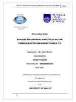
Consider
a La
sandwich
beam
with
numberedfrom
frombottom
bottom
to
as shown in
Consider
hhsandwich
beam
with
the
layers
being
to top
toptop
as shown
shown
Consider
aLL
×bhb××
sandwich
beam
withthe
thelayers
layers being
being numbered
as
Figure in1.
The
FG
sandwich
beam
is
composed
of
two
FG
face
layers
and
a
FG
porous
core.
The
top and
porous core.
core. The
The
inFig.
Fig.1.1. The
TheFG
FGsandwich
sandwich beam
beam isis composed
composed of
of two
two FG face layers and an FG porous
bottomtop
faces
are
at z faces
coordinates.
The
beam is assumed
to beis placed
ontoWinkler
elastic
foundation. It
h 2are
bottom
atat zz == ±h/2
coordinates.
The
assumed
be placed
placed
on Winkler
Winkler
topand
and
bottom
faces
are
±h/2
coordinates.
The beam
on
elastic
foundation.
ItItisisnumbered
by
thickness
−h/2)
to
the
topa 1-1-1
h1 from
h / 2the
h / to
2 the
is numbered
layer thickness
ratio from
the
bottom
the top
, e.g.
z ratio
tobottom
(z = zh1 h
elasticby
foundation.
numbered
bylayer
layer
thickness
ratio
=4 −h/2)
top
(z
=
h
=
+h/2),
e.g.
a
1-1-1
FG
sandwich
beam
is
the
beam
that
has
equal
for
every
layer.
(z
=
h
=
+h/2),
e.g.
a
1-1-1
FG
sandwich
beam
is
the
beam
thickness
for
every
layer.
FG sandwich4 4beam is the beam that has equal thickness for every layer.
z
Metal
h4
h3
Ceramic
E1; G1; 1
0
h2
h1
x
h
b
L
Ceramic
Metal
Figure
1.Sandwich
Sandwichbeam
beamwith
with functionally
functionally
graded
layers
Figure
beam
graded
porous
core and
layers
Figure
1. 1.Sandwich
with
functionally
graded
porous
coreFGM
andface
FGM
face layers
The Young’s modulus of elasticity and the mass density of each layers vary through the thickness
Young’s
modulus
ofelasticity
elasticityand
and the
the mass
mass density
density of each layers vary through the
Young’s
modulus
the thickness
thickness
according The
toThe
the
following
laws of
[8].
p
p
z h3
z h3
24
(3)
E ( z ) ( Ec Em )
( c m )
Em ; ( z ) 24
m with z h3 , h4
h
h
h
h
4
3
4
3
z
z
(2)
E (2) ( z ) Em 1 e0 cos
with z h2 , h3
; ( z ) m 1 em cos
h3 h2
h3 h2
(3)
(1)
Hung, D. X., Truong, H. Q. / Journal of Science and Technology in Civil Engineering
according to the following laws [8].
p
p
z − h3
z − h3
+ Em ; ρ(3) (z) = (ρc − ρm )
+ ρm with z ∈ [h3 , h4 ]
h4 − h3
h4 − h3
πz
πz
E (2) (z) = Em 1 − e0 cos
; ρ(2) (z) = ρm 1 − em cos
with z ∈ [h2 , h3 ] (1)
h3 − h2
h3 − h2
p
p
z − h1
z − h1
E (1) (z) = (Ec − Em )
+ Em ; ρ(1) (z) = (ρc − ρm )
+ ρm with z ∈ [h1 , h2 ]
h2 − h3
h2 − h3
E (3) (z) = (Ec − Em )
where E(z), ρ(z) are Young’s modulus and mass density at z coordinate; Em , ρm and Ec , ρc are Young’s
modulus and mass density respectively of metal and ceramic; e0 , em represent the coefficients of
porosity and of mass density.
e0 = 1 − E2 /E1 ,
em = 1 − ρ2 /ρ1
(2)
with E1 , ρ1 and E2 , ρ2 are the maximum and minimum values of Young’s modulus and of mass density
of the porous core.
3. General form of shear deformation beam theories
3.1. Displacement field
The displacement field of the beam is assumed having the following general form.
u(x, z, t) = u0 (x, t) + f1 (z)
∂w0
+ f2 (z)θ x ,
∂x
w(x, z, t) = w0 (x, t)
(3)
where u0 , w0 are the in plane displacement components in the x, z directions; θ x is the mid-plan
rotation of transverse normal; f1 (z), f2 (z) are the functions depending on the beam theory and shown
in Table 1.
Table 1. Detail of functions f1 (z), f2 (z) depending on the beam theory
Beam theory
Euler–Bernoulli
Notation
f1 (z)
f2 (z)
CBT
−z
0
Timoshenko
FSDBT
Parabolic shear deformation beam theory [16]
PSDBT
−z
Trigonometric shear deformation beam theory [14]
TSDBT
−z
Exponential shear deformation beam theory [17]
ESDBT
−z
−z
z
4 z
3 h
h
πz
sin
π
h
2
ze−2(z/h)
z 1−
2
3.2. Strain and stress fields
The strain field is obtained from the general displacement field using the following relations.
ε xx =
∂u ∂u0
∂2 w0
∂θ x
∂u ∂w
∂w0
=
+ f1 (z) 2 + f2 (z)
γ xz =
+
= 1 + f1 (z)
+ f2 (z)θ x
∂x
∂x
∂x
∂z ∂x
∂x
∂x
25
(4)
Hung, D. X., Truong, H. Q. / Journal of Science and Technology in Civil Engineering
The stress field in the ith layer is determined from the strain field via the Hooke law, in which the
coefficient of Poisson ν is assumed to be constant across the thickness of the beam.
i
σ xx
σ xz
E(z)
2
= 1 − ν
0
0
K s E(z)
2(1 + ν)
i
ε xx
γ xz
i
(5)
where K s is shear correction factor, K s = 5/6 for Timoshenko theory and K s = 1 otherwise.
3.3. Hamilton’s principle and equations of motion
The Hamilton’s principle is written as following.
T
0
(δU + δV − δK)dt = 0
(6)
where δU, δV, δK are respectively first variation of virtual strain energy, of virtual work done by
external forces and of virtual kinetic energy of the beam.
First variation of the virtual strain energy.
L
(σ xx δε xx + σ xz δγ xz ) dAdx
δU =
0
L
A
σ xx δ
=
0
L
A
N xx δ
=
0
L
−
=
0
+
0
∂u0
∂2 w0
∂θ x
∂w0
+ M xx δ
+ F xx δ
+ Q xz δ
+ H xz δθ x dx
∂x
∂x
∂x
∂x2
∂N xx
∂M xx ∂w0
∂F xx
∂Q xz
δu0 −
δ
−
δθ x −
δw0 + H xz δθ x dx
∂x
∂x
∂x
∂x
∂x
N xx δu0 |0L
L
=
∂2 w0
∂θ x
∂w0
∂u0
+ f1 (z) 2 + f2 (z)
+ σ xz δ 1 + f1 (z)
+ f2 (z)θ x dAdx
∂x
∂x
∂x
∂x
−
∂w0
+ M xx δ
∂x
L
0
(7)
+ F xx δθ x |0L + Q xx w0 |0L
∂2 M
∂N xx
∂Q xz
∂F xx
xx
δu0 +
δw0 −
δθ x −
δw0 + H xz δθ x dx
∂x
∂x
∂x
∂x2
+ N xx δu0 |0L + M xx δ
∂w0
∂x
L
0
+ F xx δθ x |0L + Q xx w0 |0L −
L
∂M xx
δw0
∂x
0
where
N xx =
σ xx dA;
A
M xx =
f1 (z)σ xx dA;
F xx =
A
Q xz =
f2 (z)σ xx dA;
A
1 + f1 (z) σ xz dA;
A
H xz =
f2 (z)σ xz dA
A
26
(8)
Hung, D. X., Truong, H. Q. / Journal of Science and Technology in Civil Engineering
- First variation of the virtual work done by external forces.
L
δV = −
0
(q − kn w0 ) δw0 dx
(9)
where q is distributed transverse load (q = 0 in this case) and kn is Winkler foundation stiffness.
- First variation of the virtual kinetic energy.
L
ρ(z) (˙uδ˙u + wδ
˙ w)
˙ dAdx
δK =
0
L
A
ρ(z) u˙ 0 + f1 (z)
=
A
0
∂w˙ 0
∂w˙ 0
+ f2 (z)θ˙ x δ˙u0 + f1 (z)δ
+ f2 (z)δθ˙ x + w˙ 0 δw˙ 0 dAdx
∂x
∂x
u˙ δ˙u + f (z)˙u δ ∂w˙ 0 + f (z)˙u δθ˙ + f (z) ∂w˙ 0 δ˙u + f 2 (z) ∂w˙ 0 δ ∂w˙ 0
1
0
2
0 x
1
0
0 0
1
∂x
∂x
∂x
∂x
=
ρ(z)
∂
w
˙
∂
w
˙
0 ˙
0
2
+ f1 (z) f2 (z)
δθ x + f2 (z)θ˙ x δ˙u0 + f1 (z) f2 (z)θ˙ x δ
+ f2 (z)θ˙ x δθ˙ x + w˙ 0 δw˙ 0
0 A
∂x
∂x
L
I0 u˙ 0 δ˙u0 + I1 u˙ 0 δ ∂w˙ 0 + I3 u˙ 0 δθ˙ x + I1 ∂w˙ 0 δ˙u0 + I2 ∂w˙ 0 δ ∂w˙ 0
∂x
∂x
∂x
∂x
=
dx
∂
w
˙
∂
w
˙
0
0 ˙
˙
˙
˙
˙
δ
θ
+
I
θ
δ˙
u
+
I
θ
δ
+
I
θ
δ
θ
+
I
w
˙
δ
w
˙
+I
x
3
x
0
4
x
5
x
x
0
0
0
4
0
∂x
∂x
2
L
I u˙ δ˙u − I ∂˙u0 δw˙ + I u˙ δθ˙ + I ∂w˙ 0 δ˙u − I ∂ w˙ 0 δw˙
0
0 0 0 1 ∂x 0 3 0 x 1 ∂x 0 2 ∂x2
dx
=
˙x
∂w˙ 0 ˙
∂
θ
˙
˙
˙
+I4
δθ x + I3 θ x δ˙u0 − I4
δw˙ 0 + I5 θ x δθ x + I0 w˙ 0 δw˙ 0
0
∂x
∂x
L
∂w˙ 0
L
L
+ I1 u˙ 0 δw˙ 0 |0 + I2
δw˙ 0 + I4 θ˙ x δw˙ 0 0
∂x
0
L
dAdx
(10)
Substituting the expressions (7), (9) and (10) into equation (6) one obtains.
∂F xx
∂2 M xx
∂Q xz
∂N xx
−
δw
−
δu
+
δθ
−
δw
+
H
δθ
+
k
w
δw
0
0
x
0
xz
x
n
0
0
T L
∂x
∂x
∂x
∂x2
2
∂
w
˙
∂
w
˙
∂˙
u
0
−I0 u˙ 0 δ˙u0 + I1 0 δw˙ 0 − I3 u˙ 0 δθ˙ x − I1 0 δ˙u0 + I2
0=
δ
w
˙
dxdt
0
2
∂x
∂x
∂x
0 0
˙
∂w˙ 0 ˙
∂θ x
˙
˙
˙
−I4
δθ x − I3 θ x δ˙u0 + I4
δw˙ 0 − I5 θ x δθ x − I0 w˙ 0 δw˙ 0
∂x
∂x
L
L
∂w0
∂M xx
T
L
L
N xx δu0 |0L + M xx δ
+ F xx δθ x |0 + Q xx δw0 |0 −
δw0
∂x
∂x
dt
0
0
+
L
∂
w
˙
L
0
L
−I1 u˙ 0 δw˙ 0 |0 − I2
δw˙ 0 − I4 θ˙ x δw˙ 0 0
0
∂x
0
∂w¨ 0
∂N xx
− I0 u¨ 0 − I1
− I3 θ¨ x δu0
−
∂x
∂x
T L
2
2
∂ M xx ∂Q xz
∂¨u0
∂ w¨ 0
∂θ¨ x
=
−
+ kn w0 − I1
− I2 2 − I4
+ I0 w¨ 0 δw0 dxdt
+
2
∂x
∂x
∂x
∂x
∂x
0 0
− ∂F xx − H xz − I3 u¨ 0 − I4 ∂w¨ 0 − I5 θ¨ x δθ x
∂x
∂x
L
L
∂M xx
∂w0
L
T
N xx δu0 |0L + M xx δ
+ F xx δθ x |0 + Q xx −
δw0
∂x 0
∂x
0
+
L
dt
∂w˙ 0
˙
−
I
u
˙
+
I
+
I
θ
δ
w
˙
0
1 0
2
4 x
0
∂x
0
27
(11)
Hung, D. X., Truong, H. Q. / Journal of Science and Technology in Civil Engineering
where
I0 =
ρ(z)dA;
A
I3 =
I1 =
f1 (z)ρ(z)dA;
A
f2 (z)ρ(z)dA;
f12 (z)ρ(z)dA
I2 =
A
I4 =
A
f1 (z) f2 (z)ρ(z)dA;
f22 (z)ρ(z)dA
I5 =
A
(12)
A
The equations of motion are formulated by taking Euler-Lagrange equations from (11).
δu0 :
δw0 :
δθ x :
∂w¨ 0
∂N xx
= I0 u¨ 0 + I1
+ I3 θ¨ x
∂x
∂x
∂2 M xx ∂Q xz
∂¨u0
∂2 w¨ 0
∂θ¨ x
+
k
w
¨
=
I
+
I
− I0 w¨ 0
−
+
I
n
0
1
2
4
∂x
∂x
∂x
∂2 x
∂2 x
∂F xx
∂w¨ 0
− H xz = I3 u¨ 0 + I4
+ I5 θ¨ x
∂x
∂x
(13)
3.4. Navier’s solution
Navier’s solution satisfies the boundary conditions of a simply supported beam and has the following form with α = nπ/L.
u0 =
∞
un cos (αx)cos (ωt) ;
n=1
w0 =
∞
wn sin (αx)cos (ωt) ;
n=1
θx =
∞
θn cos (αx)cos (ωt)
(14)
n=1
Take into account each term of the serie solution as a free vibration mode shape of the beam
and replace it into the equations (3), (8) and (13), one obtains the eigenvalue-equations of the free
vibration.
k11 k12 k13
m11 m12 m13 un 0
2
(15)
k21 k22 k23 − ω m21 m22 m23 wn = 0
0
k31 k32 k33
m31 m32 m33
θn
4. Numerical results
Consider a simply supported FG sandwich beam of dimensions L × 1 × h with metal foam core
of porosity coefficient e0 and FGM face layers. The FG sandwich beam is made of aluminum as
metal (Al: Em = 70 GPa, νm = 0, 3) and of Alumina as ceramic (Al2 O3 : Ec = 380 GPa, νc = 0, 3).
The beam rests on a Winkler elastic foundation of constant kn . Non-dimensional fundamental natural
frequency is defined as [18].
ωL2 ρm
ω=
(16)
h
Em
4.1. Validation
In order to verify the accuracy of present study, a simply supported FG sandwich beam with
isotropic core (e0 = 0) without elastic foundation (kn = 0) is considered. The non-dimensional fundamental natural frequencies are calculated for different face-core-face thickness ratios, two slenderness
ratios L/h = 5; 20 and power law index p = 5 using various beam theories.
The results are compared with those obtained using refined shear deformation beam theory (RSDBT) of [18] and are presented in Table 2. It can be seen that non-dimensional fundamental natural
frequencies of the parabolic shear deformation beam theory (PSDBT) are absolutely in agreement
with that of RSDBT theory in [18]. The other theories show a good agreement with RSDBT except
CBT and FSDBT show a little discrepancy.
28
Hung, D. X., Truong, H. Q. / Journal of Science and Technology in Civil Engineering
Table 2. Comparison of non-dimensional fundamental natural frequencies of FG sandwich beam
with isotropic core for various beam theories and beam configurations
p
Theory
5
RSDBT [18]
PSDBT
CBT
FSDBT
TSDBT
ESDBT
L/h = 5
L/h = 20
1-0-1
2-1-2
1-1-1
1-2-1
1-0-1
2-1-2
1-1-1
1-2-1
2.7446
2.7446
2.8082
2.7274
2.7462
2.7480
2.8439
2.8439
2.8953
2.8281
2.8451
2.8463
3.0181
3.0181
3.0741
3.0039
3.0188
3.0197
3.3771
3.3771
3.4517
3.3652
3.3772
3.3773
2.8439
2.8439
2.8483
2.8427
2.8440
2.8442
2.9310
2.9310
2.9346
2.9299
2.9311
2.9312
3.1111
3.1111
3.1149
3.1101
3.1111
3.1112
3.4921
3.4921
3.4972
3.4913
3.4921
3.4921
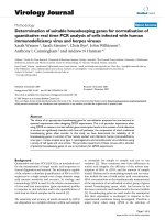
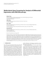
4.2. Effect of slenderness ratio L/h
Consider a 1-2-1 sandwich FG beam consist metal foam core and FGM faces resting on Winkler elastic foundation with e0 = 0.4, p = 5, kn = 107 (N/m3 ) and with different ratios L/h =
5; 10; 15; 20; 30; 40. The non-dimensional fundamental natural frequencies of the FG sandwich beam
are presented in Table 3 and their variation versus slenderness ratios are graphically depicted in Fig. 2.
Table 3. Non-dimensional fundamental natural frequency ω of 1-2-1 FG sandwich beam
with different slenderness ratios
Theory
ω
CBT
FSDBT
PSDBT
TSDBT
ESDBT
L/h
5
10
15
20
30
40
5.5914
5.1969
4.9243
4.8894
4.8542
5.7047
5.5910
5.5012
5.4889
5.4762
5.8538
5.8030
5.7615
5.7558
5.7498
6.2048
6.1775
6.1551
6.1519
6.1487
7.9592
7.9496
7.9417
7.9406
7.9395
11.4091
11.4054
11.4023
11.4018
11.4014
It is observed that the non-dimensional natural frequency increases with increasing value of slenderness ratios for all beam theories. When the ratio L/h is small, natural frequencies obtained by various theories are considerably different and they are more and more convergent when L/h increases.
This result shows important effect of the shear deformation on the short beams.
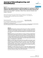
4.3. Effect of the face-core-face thickness ratios
A sandwich beam with L/h = 5, e0 = 0.4, p = 5, kn = 107 (N/m3 ) and different face-core-face
thickness ratios is studied. The non-dimensional fundamental natural frequencies are presented in
Table 4. Fig. 3 shows their variation with respect to face-core-face thickness ratios. It can be seen
that, in most case, non-dimensional fundamental natural frequency decreases as the face-core-face
thickness ratio increases. This can be explained by the reduction of bending stiffness of the beam
when the porous core thickness increases. Nonetheless, when the thickness of the core is small (1-0-1
to 3-4-3), it seems that the frequency slightly increases in two cases: CBT, FSDBT. This is due to the
low effect of shear deformation in these theories.
29
Theory
5
10
15
20
30
CBT
5.5914
5.7047
5.8538
6.2048
7.9592
FSDBT
5.1969
5.5910
5.8030
6.1775
7.9496
eory (PSDBT) are absolutely in PSDBT
agreement with4.9243
that of RSDBT
5.5012
5.7615
6.1551
7.9417
good agreement with RSDBT except
CBT and FSDBT
show a5.4889
little
TSDBT
4.8894
5.7558
6.1519
7.9406
Hung, ESDBT
D. X., Truong, H. 4.8542
Q. / Journal of5.4762
Science and 5.7498
Technology in6.1487
Civil Engineering
7.9395
7
40
11.4091
11.4054
11.4023
11.4018
11.4014
4.3. Effect of the face-core-face thickness ratios
beam
resting
0.4 ,
fferent
noncies of
Table 3
ios are
A sandwich beam with L / h 5 , e0 0.4 ,
p 5 , kn 107 ( N / m3 ) and different face-core-face
thickness ratios is studied. The non-dimensional
fundamental natural frequencies are presented in the
Table. Figure shows their variation with
respect to face-core-face thickness ratios. It can be
seen that, in most case, non-dimensional
fundamental natural frequency decreases as the facecore-face thickness ratio increases. This can be
nsional
explained by the reduction of bending stiffness of the
easing
beam when
theof porous
coreonthickness
increases. Figure 3. Effect of the face-core-face thickness ratio
L / h ratio
Figure
2. Effect
non-dimensional
eories.
Nonetheless,
when
of the core is small Figure
Figure 2. Effect
of the
L/hthickness
ratio on non-dimensional
3. Effect of thefundamental
face-core-face
thickness
ratio
on non-dimensional
natural
frequency
natural
of 1-2-1
1-2-1
sandwich
beam
(1-0-1
to frequency
3-4-3),
it seems
that the
frequency
slightly on non-dimensional fundamental natural frequency ω
natural
frequency
ω of
sandwich
beam
of FG sandwich beams
increases
in two
CBT,
FSDBT.
Thisconvergent
is due to
are considerably
different
andcases:
they are
more
and more
of FG sandwich beams
the low effect of shear deformation in these theories.
mportant effect of the shear deformation on the short beams.
Table 4. Non-dimensional natural frequency ω of sandwich beams
natural frequency of 1-2-1 FG sandwich beam with different
with different face-core-face thickness ratios
slenderness ratios
L/h
Ratio of the layer’s depth
10
15
20
30
40
Theory
1-0-1 7.9592
2-1-2 11.4091
3-2-3
1-1-1
3-4-3
14
5.7047
5.8538
6.2048
69
5.5910
5.8030
6.1775
CBT
5.5009 7.9496
5.6371 11.4054
5.6572
5.6708
5.6590
43
5.5012
5.7615
FSDBT 6.1551
5.2220 7.9417
5.3085 11.4023
5.3158
5.3090
5.2824
94
5.4889 ω 5.7558
PSDBT 6.1519
5.1898 7.9406
5.2054 11.4018
5.1883
5.1353
5.0684
42
5.4762
5.7498
6.1487
7.9395
11.4014
TSDBT
5.1858
5.1901
5.1692
5.1094
5.0375
ESDBT
5.1824
5.1743
5.1491
5.0820
5.0052
s ratios
1-2-1
1-8-1
5.5914
5.1969
4.9243
4.8894
4.8542
4.7538
4.3892
4.1615
4.1568
4.1551
, e0 0.4 ,
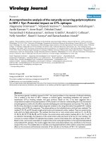
e-core-face 4.4. Effect of volume fraction of FG face layers
dimensional
Reconsider the 1-2-1 FG sandwich beam with L/h = 5, e0 = 0.4, kn = 107 (N/m3 ) and different
nted in the volume fraction indices of the face layers p = 0.1; 0.5; 1; 2; 5; 10. The obtained non-dimensional
fundamental natural frequencies ω of the beams are tabulated in Table 5. Fig. 4 exhibits the their
variation with respect to volume fraction index of the face layers. As can be seen from the presented
ation with results, the non-dimensional natural frequency increases with increasing value of volume fraction
. It can be index p of face layers. It is basically due to the fact that Young’s modulus of ceramic is higher
dimensional than those of metal. When the volume fraction p increases, the ceramic amount increases and this
as the face- makes augment to natural frequency. The effect of shear deformation on the considered beams is also
his can be
indicated in the figure.
fness of the
increases. Figure 3. Effect of the face-core-face thickness ratio
4.5. Effect of porosity coefficient of the porous core
ore is small on non-dimensional fundamental natural frequency
ncy slightly
The non-dimensional
fundamental
beamsnatural frequencies computed for a 1-2-1 sandwich beam with
of FG sandwich
is is due to L/h = 5, p = 5, kn = 107 (N/m3 ) and different values of porosity coefficient of the porous core
se theories. e = 0; 0.2; 0.4; 0.6; 0.8 to show the effect of this parameter. The results are presented in Table 6.
0
The variation of non-dimensional fundamental natural frequencies versus porosity coefficients is illustrated in the Fig. 5. The presented results show that non-dimensional natural frequency of the
30
y
1-2
371
085
054
901
743
8
increases with increasing value of volume fraction
index p of face layers. It is basically due to the fact
Figure 4. Effect of volume fraction index p of the
that Young’s modulus of ceramic is higher than those
face layers on non-dimensional fundamental
of metal. When the volume fraction p increases, the
naturalinin
frequency
of FG sandwich beams
Truong,
H. Q.
Q.
Journal
of Science
Science
and Technology
Technology
Civil Engineering
Engineering
Hung,increases
D. X., Truong,
H.
// Journal
of
Civil
ceramic amount
and this
makes
augment
to and
natural frequency.
The effect of shear
deformation
on the
considered
is also indicated
fundamental
natural
frequency
ω of
ofbeams
FG sandwich
sandwich
beams in the figure.
Table 5. Non-dimensional fundamental
natural
frequency
ω
FG
beams
values of
of volume
volume
fraction index
index
of face
face
layers beams with different values of
with different
values
fraction
of
layers
Table 5. Non-dimensional
fundamental
natural
frequency
of FG
sandwich
volume fraction index of face layers
Volume
fraction
indexindex
of the
theofface
face
layers
Volume
fraction
index
of
pp p
thickness
of sandwich beams with different face-core-face thickness
Volume
fraction
the layers
face
layers
Theory Theory
ratios
0.1
0.5 11
1
10
10
0.1
0.5
22 2
55 5
10
CBT
3.4579
4.5084
4.9964
5.3520
5.5914
5.6628
Ratio of the layer’s
depth
4.5084
4.9964
5.3520
5.5914
5.6628
CBT
3.4579
4.5084
4.9964
5.3520
5.5914
5.6628
1-8-1
3-2-3
1-1-1 FSDBT
3-4-3 FSDBT
1-2-1
1-8-1
3.2545
4.9664 5.1969
5.1969 5.2700
5.2700
4.1951 4.1951
4.6374 4.63744.9664
4.9664
5.1969
5.2700
3.2545
4.1951
4.6374
4.7538
5.6572
5.6708
5.6590
5.5914
4.7538
PSDBT
3.2120
4.0441
4.4182
4.7030
4.9243
5.0071
Tần số PSDBT
3.2120 4.3892
4.0441
4.4182
4.7030
4.9243
5.0071
4.0441
4.4182
4.7030
4.9243
5.0071
5.3158 ω 5.3090
5.2824 TSDBT
5.1969 4.3892
3.2095
4.0341
4.3999
4.6754
4.8894
4.9706
4.0341
4.3999
4.6754
4.8894
4.9706
3.2095 4.1615
4.0341
4.3999
4.6754
4.8894
4.9706
4.1615
5.1883
5.1353 TSDBT
5.0684 ESDBT
4.9243
3.2078
4.0257
4.3833
4.6490
4.8542
4.9330
4.0257
4.3833
4.6490
4.8542
4.9330
3.2078 4.1568
4.0257
4.3833
4.6490
4.8542
4.9330
4.1568
5.1692
5.1094 ESDBT
5.0375 4.8894
Effect of5.0052
porosity 4.8542
coefficient4.1551
of the porous core
4.1551
5.1491 4.5.
5.0820
yers
ers
eam with
different
e layers
d
non-
The non-dimensional fundamental
natural frequencies computed for a 1-2-1
sandwich beam with L / h 5 , p 5 ,
kn 107 ( N / m3 ) and different values of
porosity coefficient of the porous core
e0 0; 0.2; 0.4; 0.6; 0.8 to show the
effect of this parameter. The results are
presented in the Table. The variation of
non-dimensional fundamental natural
frequencies versus porosity coefficients is
ilustrated in the Figure. The presented
results
show of
that
non-dimensional
natural
of the
theFigure 5. Effect of porosity coefficient of the porous core e on
pp of
Figure
4. Effect
volume
fraction index
frequency
of
the
beam
increases
with
index
ofthe
the face
face
Figure 5.
5. Effect
Effect of
of porosity
porosity coefficient
coefficient of
of the
the porous
porous 0
Figure
4.
Effect
of
volume
fraction
index
pp of
the
Figure
fundamental
face layers on non-dimensional fundamental
of the
hibits the
n index of
presented
frequency
e fraction
o the fact
han those
eases, the
fundamental natural
natural
core ee00 on
on non-dimensional
non-dimensional natural
natural frequency
frequency ω
ω of
of
layers on non-dimensional fundamental
core
beams
natural frequency of FG sandwich beams
ment to
beams
FG sandwich
sandwich beams
beams
frequency ω of FG sandwich beams
FG
figure.
ation on the considered beams is also indicated in the figure.
fundamental
natural frequency
frequency ω
ω of
of FG
FG sandwich
sandwich beams
beams
Table
6.
Non-dimensional
fundamental
values of
of natural
ral frequency of FG sandwich beams with different values
values
of
porosity
coefficient
of
the
porous
core
with
different
values
of
porosity
coefficient
of
the
porous
core
raction index of face layers
Volume fraction index of the face layers p
Porosity coefficient
coefficient of
of the
the porous
porous core
core ee00
Porosity
0.5
1
2 Theory 5
10
4.5084
4.9964
5.3520
5.5914
5.6628
0.2
0.4
0.6
0.8
0
0.2
0.4
0.6
0.8
4.1951
4.6374
4.9664
5.1969
5.2700
5.5074
5.5914
5.6979
5.8487
5.5074
5.5914
5.6979
5.8487
4.0441
4.4182
4.7030CBT4.9243 5.4373
5.0071
5.1254
5.1969
5.2889
5.4219
FSDBT
5.1254
5.1969
5.2889
5.4219
4.0341
4.3999
4.6754
4.8894 5.0666
4.9706
4.0257
4.3833
4.6490
4.8542
4.9330
4.8879
4.9243
4.9739
5.0539
PSDBT
4.8587
4.8879
4.9243
4.9739
5.0539
ω
us core
TSDBT
ESDBT
4.8361
4.8148
4.8599
4.8599
4.8326
4.8326
4.8894
4.8894
4.8542
4.8542
4.9299
4.9299
4.8842
4.8842
4.9978
4.9978
4.9375
4.9375
porosity coefficient.
coefficient. This
This seems
seems reasonless
reasonless because
because the
the increase
increase
beam increases with the increasing porosity
reduction of
of the
the bending
bending stiffness
stiffness of
of the
the beams
beams and
and makes
makes
of the porosity of the core will entrain the reduction
has to
to notice
notice that
that this
this increase
increase of
of the
the porosity
porosity also
also entrains
entrains
decrease the natural frequency. But one has
effect is
is inverse.
inverse. Thus,
Thus, combination
combination of
of these
these two
two effects
effects
the reduction of the mass density and its effect
beam.
makes increase the natural frequency of the beam.
core ee00 on
on
Figure 5. Effect of porosity coefficient of the porous core
31
31
10
Hung, D. X., Truong, H. Q. / Journal of Science and Technology in Civil Engineering
4.6. Effect of Winkler foundation stiffness
Consider a 1-2-1 sandwich beam with
L/h = 5, e0 = 0.4, p = 5 and different Winkler elastic foundation stiffness kn =
0.5; 20; 200; 500; 1000; 2000 (×106 N/m3 ).
The results presented in Table 7 and in Fig. 6.
This figure shows that the non-dimensional
fundamental natural frequency of the beam
increases with the increasing constant of the
elastic foundation. Because when the constant
kn increases, it makes augment to the bending
stiffness of the beam and therefore entrains the
Figure
6. Effect of stiffness
of Winkler
elastic
foundation
natural fre
kn on non-dimensional
increase of the natural frequency.
Moreover
Figure
6. Effect
of stiffness
of Winkler
elastic
beams
foundation knsandwich
on non-dimensional
natural
we can also clearly observe the effect of the
frequency
ω
of
sandwich
beams
shear deformation as in the above
other
tests.
5. Conclusions
This paper
investigates
free
vibrationbeams
of sandwich
beams with
FG porous core and FGM fac
Table 7. Non-dimensional
natural
frequencythe
ω of
sandwich
with increasing
constant
Winkler
elastic
foundation.
A general
form oftheories
the displacement field and the equations of mo
of Winkler
elastic
foundation
obtained
by various
Hamilton’s principle have been established. Using this general form of various beam theorie
shows the important effect of shear deformation
on the fundamental natural frequency of shor
6
3
kn (×10
N/m
)
effects of Winkler foundation
stiffness,
transverse
shear deformation, slenderness ratio, fa
Theory
thickness ratio, volume fraction index, as well as porosity coefficient of the core on the fundam
0.5
20 investigated.
200The results 500
1000
2000
frequency
are also
show an inverse
effect of the
increase of porosity c
the core on the
fundamental 5.6303
natural frequency
beacause of5.7911
the reduction5.9860
of the mass density.
CBT
5.5895
5.5935
5.6911
ω
FSDBT
PSDBT
TSDBT
ESDBT
5.1948
5.2392
5.3051
5.4133
5.6234
References 5.1992
4.9221
4.9267
4.9691
5.0390
5.1535
1. Queheillalt, D. T., Choi, B. W., Schwartz, D. S., Wadley, H. N. G.5.3750
(2000). Creep Expansi
4.8871
4.9345 Metallurgical
5.0050 and Materials
5.1202 Transactions
5.3433A, (31A): 261-27
Ti-6Al-4V4.8918
Sandwich Structures.
2. Vancheeswaran,
Elzey, D. M.,5.0868
Wadley, H. N.5.3114
G. (2000). Simulation
4.8519
4.8566R., Queheillalt,
4.8997 D. T.,4.9707
Expansion of Porous Sandwich Structures. Metallurgical and Materials Transactions A, (
1821.
3. Bang, S. O., Cho, J. U. (2015). A Study on the Compression Property of Sandwich Com
Porous Core. International Journal of Precision Engineering and Manufacturing, (16): 11175. Conclusions
4. Conde, Y., Pollien, A., Mortensen, A. (2006). Functional grading of metal foam cores for
lightweight sandwich beams. Scripta Materialia, (54): 539-543.
This paper investigates the
vibration of sandwich
beams
with
FG porous
core
andofFGM
faces beam with a
5. free
Magnucka-Blandzi
E., Magnucki,
K. S.
(2007).
Effective
design
a sandwich
core.
Thin-Walled
Structures,
(45):
432-438.
resting on Winkler elastic foundation. A general form of the displacement field and the equations
6. Bui,
T.Q., Khosravifard,
A., Zhang, Ch.,
Hematiyan,
M. R.,form
Golub,ofM.
V. (2013). Dynami
of motion through Hamilton’s
principle
have been established.
Using
this general
various
sandwich beams with functionally graded core using a trully meshfree radial point interpola
beam theories, the paper showsEngineering
the important
effect of
shear
deformation on the fundamental natural
Structures,
(47):
90-104.
frequency of short beams. The
effects of
Winkler
stiffness,
transverse
deformation,
7. Sayyad,
A.S,
Ghugal,foundation
Y. M. (2015).
On the free
vibrationshear
analysis
of laminated composite a
slenderness ratio, face-core-faceplates:
thickness
ratio,
volume
fraction
index,
well as results.
porosity
coefficient
A review
of recent
literature
with
someas
numerical
Composite
Structures, (129)
8.
Chen,
D.,
Kitipornchai,
S.,
Yang,
J.
(2016).
Nonlinear
free
vibration
of
shear
of the core on the fundamental natural frequency are also investigated. The results show an inversedeformable san
a functionally graded porous core. Thin-Walled Structures, (107): 39-48.
effect of the increase of porositywith
coefficient
of the core on the fundamental natural frequency because
9. Sayyad, A.S., Ghugal, Y. M. (2017). Bending, buckling and free vibration of laminated co
of the reduction of the mass density.
sandwich beams: A critical review of literature. Composite Structures.
10. Moschini, S. (2014). Vibroacoustic modeling of sandwich foam core panels. Thesis, Po
Milano.
References
11. Hajianmaleki, M., Qatu, M. S. (2013). Vibration of straight and curved composite beam
Composite Structures, (100): 218-232.
[1] Queheillalt, D. T., Wadley, H. N. G., Choi, B. W., and Schwartz, D. S. (2000). Creep expansion of porous
Ti-6Al-4V sandwich structures. Metallurgical and Materials transactions A, 31(1):261–273.
32
Hung, D. X., Truong, H. Q. / Journal of Science and Technology in Civil Engineering
[2] Vancheeswaram, R., Queheillalt, D. T., Elzey, D. M., and Wadley, H. N. G. (2001). Simulation of the
creep expansion of porous sandwich structures. Metallurgical and Materials Transactions A, 32(7):1813–
1821.
[3] Bang, S. O. and Cho, J. U. (2015). A study on the compression property of sandwich composite with
porous core. International Journal of Precision Engineering and Manufacturing, 16(6):1117–1122.
[4] Conde, Y., Pollien, A., and Mortensen, A. (2006). Functional grading of metal foam cores for yieldlimited lightweight sandwich beams. Scripta Materialia, 54(4):539–543.
[5] Magnucka-Blandzi, E. and Magnucki, K. (2007). Effective design of a sandwich beam with a metal foam
core. Thin-Walled Structures, 45(4):432–438.
[6] Bui, T. Q., Khosravifard, A., Zhang, C., Hematiyan, M. R., and Golub, M. V. (2013). Dynamic analysis of
sandwich beams with functionally graded core using a truly meshfree radial point interpolation method.
Engineering Structures, 47:90–104.
[7] Sayyad, A. S. and Ghugal, Y. M. (2015). On the free vibration analysis of laminated composite and
sandwich plates: A review of recent literature with some numerical results. Composite Structures, 129:
177–201.
[8] Chen, D., Kitipornchai, S., and Yang, J. (2016). Nonlinear free vibration of shear deformable sandwich
beam with a functionally graded porous core. Thin-Walled Structures, 107:39–48.
[9] Sayyad, A. S. and Ghugal, Y. M. (2017). Bending, buckling and free vibration of laminated composite
and sandwich beams: A critical review of literature. Composite Structures, 171:486–504.
[10] Moschini, S. (2014). Vibroacoustic modeling of sandwich foam core panels. PhD thesis, Politecnico Di
Milano, Italy.
[11] Hajianmaleki, M. and Qatu, M. S. (2013). Vibrations of straight and curved composite beams: A review.
Composite Structures, 100:218–232.
[12] Mashat, D. S., Carrera, E., Zenkour, A. M., Al Khateeb, S. A., and Filippi, M. (2014). Free vibration
of FGM layered beams by various theories and finite elements. Composites Part B: Engineering, 59:
269–278.
[13] Filippi, M., Carrera, E., and Zenkour, A. M. (2015). Static analyses of FGM beams by various theories
and finite elements. Composites Part B: Engineering, 72:1–9.
[14] Ghugal, Y. M. and Shimpi, R. P. (2001). A review of refined shear deformation theories for isotropic and
anisotropic laminated beams. Journal of Reinforced Plastics and Composites, 20(3):255–272.
[15] Gherlone, M. (2013). On the use of zigzag functions in equivalent single layer theories for laminated
composite and sandwich beams: a comparative study and some observations on external weak layers.
Journal of Applied Mechanics, 80(6):061004.
[16] Pradhan, K. K. and Chakraverty, S. (2014). Effects of different shear deformation theories on free vibration of functionally graded beams. International Journal of Mechanical Sciences, 82:149–160.
[17] Karama, M., Afaq, K. S., and Mistou, S. (2003). Mechanical behaviour of laminated composite beam
by the new multi-layered laminated composite structures model with transverse shear stress continuity.
International Journal of Solids and Structures, 40(6):1525–1546.
[18] Vo, T. P., Thai, H. T., Nguyen, T. K., Maheri, A., and Lee, J. (2014). Finite element model for vibration and buckling of functionally graded sandwich beams based on a refined shear deformation theory.
Engineering Structures, 64:12–22.
33