Effect of shear modulus on the performance of prototype un bonded fiber reinforced elastomeric isolators
Bạn đang xem bản rút gọn của tài liệu. Xem và tải ngay bản đầy đủ của tài liệu tại đây (4.09 MB, 10 trang )
Journal of Science and Technology in Civil Engineering NUCE 2018. 12 (5): 10–19
EFFECT OF SHEAR MODULUS ON THE PERFORMANCE
OF PROTOTYPE UN-BONDED FIBER REINFORCED
ELASTOMERIC ISOLATORS
Van Thuyet Ngoa,∗
a
Structural Engineering Division, Department of Civil Engineering, Thuyloi University,
175 Tay Son street, Dong Da district, Hanoi, Vietnam
Article history:
Received 10 May 2018, Revised 10 July 2018, Accepted 30 August 2018
Abstract
Un-bonded fiber reinforced elastomeric isolator (U-FREI) is light weight and facilitates easier installation in
comparison to conventional steel reinforced elastomeric isolators (SREI), in which fiber layers are used as
reinforcement to replace steel shims as are normally used in conventional isolators. Shear modulus of elastomer
has significant influence on the force-displacement relationship of U-FREI. However, a few studies investigated
the effect of shear modulus on the horizontal behavior of prototype U-FREI in literature. In this study, effect of
shear modulus on performance of prototype U-FREIs is investigated by both experiment and finite element (FE)
analysis. It is observed that reduction in horizontal stiffness of U-FREI with increasing horizontal displacement
is due to both rollover deformation (or reduction in contact area of isolator with supports) and shear modulus
of elastomer. Reasonable agreement is observed between the findings from experiment and FE analysis.
Keywords: base isolator; prototype un-bonded fiber reinforced elastomeric isolator; rollover deformation; shear
modulus; cyclic test.
/>
c 2018 National University of Civil Engineering
1. Introduction
Base isolation is an efficient and viable method to reduce the vulnerability of structure in high
seismic risk zone. Earthquake energy transmitted to the structure can be reduced by lengthening
the fundamental horizontal period of structure. Base isolators are installed in between substructure
and superstructure to achieve the desired horizontal period of structure. Conventional steel reinforced
elastomeric isolators (SREIs) consist of alternating layers of rubber bonded to intermediate steel shims
with two steel end plates at top and bottom. In general, SREIs are often applied for large, important
buildings like hospitals and emergency centers, in developed countries such as United States, Japan,
New Zealand, Italy, etc. This limited use is largely due to high material, manufacturing and installation
costs. It is expected that the use of seismic isolators can be extended to ordinary low-rise and mediumrise buildings if the weight and cost of the isolators are reduced. In view of this, fiber reinforced
elastomeric isolators (FREIs) are proposed by replacing steel shims in conventional isolators by multilayer of fiber fabric as reinforcement sheets to reduce their weight and cost. An un-bonded fiber
reinforced elastomeric isolator (U-FREI) is a significant effort to improve FREI by removing two steel
end plates and installing directly between the substructure and superstructure without any connection
∗
Corresponding author. E-mail address: (Ngo, V. T.)
10
Ngo, V. T. / Journal of Science and Technology in Civil Engineering
to these boundaries. Using U-FREI would reduce the weight and cost, easier installation, and can be
made as a long strip and then easily cut to the required size. It means that the U-FREIs can be used
for low-rise and medium-rise buildings subjected to earthquake loading in the developing countries
like Vietnam, Indonesia, Taiwan, Nepal, etc.
Some studies were conducted in recent time for obtaining the mechanical characteristics of FREIs
leading to better understanding of their behavior. Kelly and Takhirov [1] studied the mechanical properties of U-FREIs by theoretical and experimental analysis. Toopchi-Nezhad et al. [2] carried out
experimental study to investigate the lateral behavior of U-FREI. Strauss et al. [3] presented experimental tests to evaluate shear modulus and damping coefficient of elastomeric bearings with various
reinforcing materials and under various loadings, support conditions. Dezfuli and Alam [4] prepared
scaled U-FREIs with different initial shear moduli, number of elastomer layers, number of fiber layers, thickness of elastomer layers and experimentally evaluated the vertical and horizontal response
of U-FREIs. Ngo et al. [5, 6] studied the horizontal stiffness and the effect of horizontal loading
direction on performance of square U-FREI by both experiment and finite element (FE) analysis.
These studies indicate that the behavior of elastomeric isolators is affected by some factors such as
material properties, sizes and shapes, loadings and directions of loading, friction between the surfaces
of U-FREI and support areas, etc. An effort to study the effect of shear modulus on the behavior of
elastomeric isolators was conducted by Strauss et al. [3]. They conducted laboratory tests to study the
effect of shear modulus of scaled bonded FREI as well as SREI of various dimensions, under good
combinations of vertical load and cyclic horizontal displacement up to 1.0tr (tr is the total thickness
of elastomer/rubber layers of isolator). Dezfuli and Alam [4] evaluated experimentally the reduction
in effective shear modulus of scaled U-FREIs with increasing horizontal displacement up to 1.0tr .
The effect of shear modulus on horizontal response of U-FREI specimens in [4] is not clear because
of different sizes and shape factors of these specimens. It is necessary to study the effect of shear
modulus on the response of U-FREIs with the same sizes and shape factors under the action of larger
horizontal displacement. Further, most of previous studies were carried out on scaled models of UFREIs with relatively low shape factor (less than 10). According to Naeim and Kelly [7], shape factor
(S ) is defined as the ratio of the loaded area to load free area of an elastomer layer. Range of shape
factor values of typical isolators for seismic isolation is from 10 to 20 [7]. Thus, the effect of shear
modulus on horizontal response of prototype U-FREIs with high shape factors should be studied. This
will have huge significance in design and production of prototype isolators for field application.
This study investigates the performance of prototype U-FREIs under cyclic loading by both experiments and FE analysis. In experiments, four prototype specimens with the same sizes in plan and two
different values of shear modulus are produced, and then the characteristic properties including the
horizontal stiffness as well as the energy dissipation capacity and the equivalent viscous damping are
assessed. These specimens are tested under the same constant vertical pressure and cyclic horizontal
displacement up to 0.89tr . In addition, the investigation of the behavior of isolators could be done up
to very large applied horizontal displacements of 1.50tr using FE method. Numerical results are validated with experimental findings for cyclic horizontal displacement up to 0.89tr , a limit considered
from the requirement of safety of the test set up during actual experiment. From experimental and
numerical results, effects of shear modulus on the behavior of prototype U-FREIs are evaluated.
2. Details of test specimens
Specimens are produced to use in an actual building in India with the support of METCO Pvt. Ltd.,
Kolkata, India. Four specimens are manufactured by vulcanizing elastomer layers and bi-directional
11
requirement of safety of the test set up during actual experiment. From experimental and numerical
results, effects
of shear
modulus
on the behavior of prototype U-FREIs are evaluated.
2. Details
of test
specimens
2. Details of testSpecimens
specimens are produced to use in an actual building in India with the support of METC
Ltd., Kolkata,
India. Four
arebuilding
manufactured
by vulcanizing
elastomer
Specimens
are produced
to usespecimens
in an actual
in India with
the support of
METCO layers
Pvt. and bi-dire
o
o
◦
◦
(0 /90
) carbon
fiber
Twostrips
longofstrips
of laminated
with two
different
values of initi
Ltd.,(0Kolkata,
India.
Four
arelong
manufactured
by vulcanizing
andvalues
bi-directional
/90
) carbon
fiber specimens
fabric.fabric.
Two
laminated
pads elastomer
withpads
two layers
different
of initial
o
(0o/90
)
carbon
fiber
fabric.
Two
long
strips
of
laminated
pads
with
two
different
values
of
initial
shear
modulus
are
made
from
eighteen
elastomer
layers
interleaved
with
seventeen
carbon
shear modulus are made from eighteen elastomer layers interleaved with seventeen carbon fiber fabricfiber fabric
modulus
areStrip
made
from
eighteen
layers
with
carbon
fibersimilar
fabric
layers.
Strip
with
initial
shearelastomer
modulus,
G 0.78
asinterleaved
0.78
is seventeen
designated
aswhile
type
A,
while
similar
layers.
with
initial
shear
modulus,
G
as
MPa MPa
is designated
as type
A,
such
strip such str
Stripwith
with
initial
shear
modulus,
G
as
0.78
MPa
is
designated
as
type
A,
while
similar
such
strip
with
value of
of G as 0.90
as as
type
B. The
thickness
of each
layer islayer
5 mm,is 5 mm, wh
value
0.90MPa
MPaisisdesignated
designated
type
B. The
thickness
of elastomer
each elastomer
value
of Gthat
as 0.90
MPafiber
is designated
as type
B.and
Thetotal
thickness
ofofeach
elastomer
layer
is mm.
5 mm,
while that
while
of
each
layer
is
0.55
mm
height
each
bearing
is
100
Subsequently,
of each fiber layer is 0.55 mm and total height of each bearing is 100 mm. Subsequently, four spe
of each
layer is(including
0.55 mm and
total specimens
height of each
bearing
is
100A,mm.
Subsequently,
four (1,2)
specimens
fourfiber
specimens
of two
from
sheet
type
denoted
as isolator
and specimens
two
(including
of two specimens
fromA,sheet
type
A,
denoted
as
isolator
A(1,2) Aand
two
fro
(including
of
two
specimens
from
sheet
type
denoted
as
isolator
A
and
two
specimens
from
sheet
(1,2)
specimens from sheet type B, denoted as isolator B(1,2) ) are cut to squared size of 250 × 250 × 100
B, as
denoted
as (1,2)
isolator
B(1,2)
are cutsizeto ofsquared
size of 250x250x100
mm.
typemm.
B, type
denoted
isolator
) are cut
to )squared
250x250x100
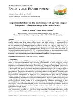
view
of aAoftypical vie
A typical
view
of aBprototype
isolator
with layer
details
is shown inmm.
Fig. A
1. typical
The shape
factor
prototype
isolator with
layer
details
is shown
Fig. 1. The
shape factor are
of these
isolators are S
prototype
isolator with
details
is shown
in Fig.
1. higher
The in
shape
12.5,
these isolators
are Slayer
= 12.5,
which
is significantly
thanfactor
those of
of these
modelisolators
FREIs usedSin= most
of
which
isinvestigations.
significantly
higher
those
model
FREIs
in isolators
mostinvestigations.
ofarethe
previous
investi
which
significantly
higher than
those ofthan
model
FREIs
used inproperties
most of used
the
previous
theisprevious
Geometrical
details
andofmaterial
of the
shown
in
Geometrical
details
and
material
properties
of
the
isolators
are
shown
in
Table
1.
Geometrical
details and material properties of the isolators are shown in Table 1.
Table
1.
Ngo, V. T. / Journal of Science and Technology in Civil Engineering
(a) Elastomer and fiber layers in prototype U(a) Elastomer and fiber layers in prototype U-FREI
(b) 3D view of a typical
FREI and fiber layers in prototype
(b)U3D view ofU-FREI
a typical
U-FREI specimen
(a) Elastomer
specimen
FREI
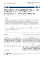
Fig.
1. 1.
Details
Figure
Detailsofofprototype
prototypeU-FREI
U-FREI specimen
specimen
3. Experimental investigations
(b) 3D view of a typical U-FREI spe
Fig. 1. Details of prototype U-FREI specimen
Table 1. Geometrical details and material properties of prototype U-FREI
3.1 Experimental
set-up
3. Experimental
investigations
Description Isolator
A
Isolator B(1,2)
All specimens are tested at Structural Engineering Laboratory, (1,2)
Indian Institute of Technology
3.1 Experimental set-up
Size of specimen,
(mm)
250 ×load
250and
× 100
250varying
× 250 ×cyclic
100
(IIT) Guwahati,
India under
simultaneous action of a constant vertical
horizontal
NumberThe
ofAll
elastomer
layer,test
ne setup
18
displacement.
experimental
is shown
in Fig. 2.Engineering
A couple18
specimen
is put one
aboveInstitute
the
specimens
are
tested
at Structural
Laboratory,
Indian
of Tech
Thickness
of single
elastomer
te , The
(mm)
other and
separated
by a steel
spacerlayer,
block.
bearing specimens are5.0
in contact with the 5.0
upper and
(IIT) Guwahati, India under simultaneous action of a constant vertical load and horizontal varying
lower Total
surfaces
of the
steel block.tr ,However,
these bearings are without 90
any physical connection
height
of elastomer,
(mm)
90 to the
displacement.
The
experimental
test
setup
is
shown
in
Fig.
2.
A
couple
specimen
is put one ab
surfaces
of theofsteel
block
andlayer,
hence
Number
carbon
fiber
n f mimic the un-bonded condition.17A horizontally placed
17 servoother
and
separated
a steel
spacer block.
specimens
are in0.55
contact
hydraulic
actuator
MTSby
USA)
connected
to theThe
steelbearing
block
for
the application
of
cyclic with the up
Thickness
of (make:
single
fiber
layer,
t f ,is(mm)
0.55
lowerfactor,
of theA steel
block.
these
bearings
without
any
physical connection
displacements
tosurfaces
the Sassembly.
constant
designHowever,
vertical load
of 350
kN
(or are
a constant
vertical
pressure
Shape
12.5
12.5
surfaces
of of
theelastomer,
steel block
and hence mimic the un-bonded
condition. A
horizontally placed
Shear
modulus
G, (MPa)
0.78
0.90
3
Elastic
modulus
of
carbon
fiber
laminate,
E,
(GPa)
40
40
hydraulic actuator (make: MTS USA) is connected to the steel block for the application of
Poisson’s
ratio of carbon
fiber laminate,
µ
0.20
0.20
displacements
to the assembly.
A constant
design vertical
load of 350 kN (or
a constant vertical p
3
3. Experimental investigations
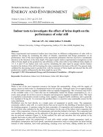
3.1. Experimental set-up
All specimens are tested at Structural Engineering Laboratory, Indian Institute of Technology
(IIT) Guwahati, India under simultaneous action of a constant vertical load and horizontal varying
cyclic displacement. The experimental test setup is shown in Fig. 2. A couple specimen is put one
above the other and separated by a steel spacer block. The bearing specimens are in contact with the
12
Thickness of single fiber layer, tf , (mm)
Shape factor, S
12.5
Shape factor, S
0.55
0.55
12.5
12.5
12.5
Shear modulus of elastomer, G, (MPa)
0.78
0.90
Ngo,
V. T. / Journal
of Science and
Shear
modulus
of elastomer,
G, Technology
(MPa) in Civil Engineering
0.78
0.90
upper and
lower surfaces
of the
steellaminate,
block. However, these bearings are without any physical conElastic
modulus
of carbon
fiber
Elastic
modulus
of
fibermimic
laminate,
and hence
the un-bonded
E,nection
(GPa)to the surfaces of the steel blockcarbon
40
40 condition. A horizontally
E,
(GPa)
placed servo-hydraulic actuator (make: MTS USA) is connected to the 40
steel block for 40
the application
of cyclic displacements
to fiber
the assembly.
A constant
design
Poisson's
ratio of carbon
laminate,
µ
0.20 vertical load
0.20of 350 kN (or a constant verPoisson's
of carbon
fiber laminate,
µ a compression
0.20 testing 0.20
tical pressure of 5.6
MPa) isratio
applied
using hydraulic
jack from
machine, where
the assemblage of bearings and steel block is housed. The magnitudes of vertical loads correspond to
factored column loads and the values are obtained from the analysis of the actual building.
Thuyet,
N. V.2. /Schematic
Journal ofrepresentation
Science andand
Technology
in Civil Engineering
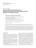
Figure
actual experimental
set-up
2. Schematicand
representation
and actualset-up
experimental set-up
Fig. 2. SchematicFig.
representation
actual experimental
acement of frequency f = 0.025 Hz are applied continuously for four levels of displacement
Details
ofofinput
displacement
history
3.2.
Details
input
displacement
ails
of input
displacement
history
itudes
as 3.2
20
mm
(0.22t
40
mm (0.44thistory
r),
r), 60 mm (0.67tr) and 80 mm (0.89tr) as shown in Fig. 3. The
The
experimental
investigations
are carried
outcarried
by subjecting
the isolator
cyclic
displace-horizontal
rimental
investigation
of the behavior
U-FREIs
is out
performed
up under
to under
the
applied
Theinvestigations
experimental
investigations
areby
by
the
isolator
cyclic
The
experimental
are
carriedof out
subjecting
the subjecting
isolator
cyclic under
ment,
while
maintaining
a
constant
vertical
pressure
on
the
isolator.
Three
cycles
of
sinusoidal
disacement
of
80
mm, considering
the
overall
safety
of the
testpressure
set-up.on
All
in this
study
are used
displacement,
while
maintaining
a constant
vertical
thespecimens
isolator.
Three
cycles
of sinusoidal
ment, while
maintaining
a constant
vertical
pressure
isolator.
Three
cycles
of
sinusoidal
placement
of frequency
f = 0.025
Hz are
appliedon
continuously
for four
levels
of displacement
ampliactual building
in mm
India
after
being tested. Thus, specimens
are tested with the maximum value of
tudes as 20
(0.22t
r ), 40 mm (0.44tr ), 60 mm (0.67t4
r ) and 80 mm (0.89tr ) as shown in Fig. 3. The
ed horizontal
displacement
of 80
to4keepof specimens
from anyupdamage.
Horizontal
experimental
investigation
of mm
the behavior
U-FREIs is performed
to the applied
horizontaldisplacement
displacement
of
80
mm,
considering
the
overall
safety
of
test
set-up.
All
specimens
in
this
study
are
used
corresponding horizontal forces are measured using in-built linear variable differential transformer
in ancell
actual
in India after being tested. Thus, specimens are tested with the maximum value
DT) and load
of building
the actuator.
of applied horizontal displacement of 80 mm to keep specimens from any damage. Horizontal displacement and corresponding horizontal forces are measured using in-built linear variable differential
transformer (LVDT) and load cell of the actuator.
Figure 3. Applied horizontal displacement history
Fig. 3. Applied horizontal displacement history
Experimental results
a) Deformed shape
13
the contact surfaces without any damage. The reduction in contact area due to
to the reduction in effective horizontal stiffness of isolators and results nonline
large displacement. Ngo, V. T. / Journal of Science and Technology in Civil Engineering
3.3. Experimental results
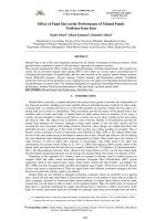
a. Deformed shape
Deformed shape of a typical specimen as obtained from experimental tests at 80 mm amplitude of horizontal displacement is shown in Fig. 4.
The top and bottom surfaces of U-FREI exhibit
stable roll off the contact surfaces without any
damage. The reduction in contact area due to
rollover deformation leads to the reduction in effective horizontal stiffness of isolators and results
nonlinear behavior of elastomer at large displacement.
Figure 4. Deformed shape of U-FREI specimen
at applied horizontal displacement of 80 mm
Fig. 4. Deformed shape of U-FREI specimen at applied horizontal d
b. Hysteresis loops
The hysteresis loop of an isolator represents the relationship between shear forces and cyclic horizontal
displacements.loops
The horizontal displacements and shear forces experienced by the U-FREIs
b) Hysteresis
are measured by LVDT and load cells respectively, which are built-in the servo-hydraulic actuator.
Further, the recorded
shear
actually
represent
the applied
forces
on two specimens tested siThuyet, Thuyet,
N.
V. / forces
Journal
Science
and Technology
in Civil
Engineering
N. V. / of
Journal
of Science
and Technology
in
Civil Engineering
The hysteresis
of plot
anis isolator
represents
the relationship
multaneously
and hence, theloop
hysteresis
obtained by dividing
these measured
forces by two to betwe
rces on
oneevaluate
specimen
average
sense.
Fig.
5 shows
such
hysteresis
loops
of
different
tested tested
specimens
the in
shear
forces
on one
specimen
average
sense.
Fig.
5 shows
such
hysteresis
loopsspecimens
of
forces
on
one specimen
in average
sense.
Fig. 5inshows
such
hysteresis
loops
of different
horizontal
displacements.
The
horizontal
displacements
and
shear
forces
expe
tested
specimens considered in this study.
onsidered
indifferent
this study.
considered
in this
study.
measured by LVDT and load cells respectively, which are built-in the servothe recorded shear forces actually represent the applied forces on two specim
and hence, the hysteresis plot is obtained by dividing these measured forces b
5
(a) Specimen A(1,2)
(b) Specimen B(1,2)
(a) Specimen
A(1,2) A(1,2)
(a) Specimen
(b) Specimen
B(1,2) B(1,2)
(b) Specimen
Figure 5. Hysteresis loops of different specimens from experimentally observed data
Fig. 5. Fig.
Hysteresis
loops ofloops
different
specimens
from experimentally
observed
data data
5. Hysteresis
of different
specimens
from experimentally
observed
c. Mechanical properties of the U-FREIs
Two important parameters such as effective horizontal stiffness and equivalent viscous damping
(or damping factor) are obtained from the hysteresis loops. The effective horizontal stiffness of an
isolator at any amplitude of horizontal displacement is defined as International Building Code [8]:
c) Mechanical
properties
of the U-FREIs
c) Mechanical
properties
of the U-FREIs
h
Ke f f =
Fmax − Fmin
umax − umin
(1)
Two important
parameters
as effective
horizontal
stiffness
and equivalent
damping
Two important
parameters
such assuch
effective
horizontal
stiffness
and equivalent
viscousviscous
damping
where
Fmin
maximum
andthe
minimum
values
the
shear
force; uhorizontal
umin are
maximum
andisolator
max ,obtained
max ,stiffness
(or damping
areare
obtained
from
hysteresis
loops.
The
effective
stiffness
of an
r damping
factor)Ffactor)
are
from the
hysteresis
loops.
Theofeffective
horizontal
of an isolator
values
ofdisplacement
the horizontal
displacement.
at anyminimum
amplitude
of horizontal
displacement
is defined
as International
Building
Code [8]:
any amplitude
of horizontal
is
defined
as International
Building
Code [8]:
)
The equivalent viscous damping of isolator (β) is computed by measuring the energy dissipated in
each cycle (Wd ), which is the area enclosed byh theFhysteresis
Fmax loop.
- Fmin The magnitude of β is computed as:
maxh - Fmin
K eff = K eff =
umax - umin
umax - umin
14
(1)
, Fmin
are maximum
and minimum
the force;
shear force;
uminmaximum
are maximum
maxare
max,are
here where
Fmax, FFmin
maximum
and minimum
values values
of the of
shear
umax, uumin
and and
Ngo, V. T. / Journal of Science and Technology in Civil Engineering
β=
Wd
2πKehf f ∆2max
(2)
where ∆max is the average of the positive and negative maximum displacements, ∆max =
(|umax | + |umin |) /2.
Effective horizontal stiffness and equivalent viscous damping of these isolators at different horizontal displacement amplitudes are furnished in Table 2. It can be seen from Table 2 that the effective
horizontal stiffness of an U-FREI decreases, while the equivalent viscous damping increases with the
increase in horizontal displacement. The decreases in effective stiffness corresponding to increase in
amplitude of horizontal displacement from 20 to 80 mm are found to be 39.1%, 37.2% for specimen
A(1,2) , B(1,2) , respectively. These reductions are due to rollover deformation, which will result in an
increase in time period of the base isolated structure leading to increase in their seismic response
control efficiency.
Table 2. Experimentally evaluated mechanical properties of U-FREIs
Amplitude (mm)
u/tr
20
40
60
80
0.22
0.44
0.67
0.89
Isolator A(1,2)
Kehf f
(kN/m)
464.26
403.41
324.22
282.60
Isolator B(1,2)
β (%)
5.18
6.94
11.15
11.83
Kehf f
(kN/m)
507.26
410.21
339.01
318.68
β (%)
5.00
9.67
12.02
10.02
4. FE analysis
FE analyses of these isolators are also conducted under simultaneous action of constant vertical
pressure and cyclic horizontal displacement by ANSYS v.14.0. FE analysis is used to simulate the
behavior of these isolators up to very large horizontal displacement amplitude of 1.50tr , although experimental investigation is carried out for horizontal displacement amplitude up to 0.89tr because of
practical constraint. Loading protocol considered in FE analysis is similar to that considered in experimental investigation. The comparison of results from numerically simulated model and experimental
observations is performed to assess the accuracy of FE analysis.
4.1. Element type for FE model
In the FE model of U-FREIs, the elastomer and fiber reinforcement are modeled using SOLID185,
SOLID46 respectively. Two rigid horizontal plates are considered at the top and bottom of the isolator
to represent the superstructure and substructure. Vertical load and horizontal displacement are applied
at the top plate, while all degrees of freedom of bottom plate are constrained.
In order to study U-FREI, contact element CONTA173 is used to define the exterior elastomer
surfaces and target element TARGE170 is used to define the interior surface of top and bottom rigid
plates. The model is meshed with hexagonal volume sweep.
15
Ngo, V. T. / Journal of Science and Technology in Civil Engineering
Thuyet, N. V. / Journal of Science and Technology in Civil Enginee
4.2. Material model
Thuyet,
V.as
/ Journal
ofinScience
Civil
Material properties
ofN.
shown
Table
1and
areTechnology
usedininCivil
FE
Elastomer isare
modeled
Thuyet,
V.experimental
/N.Journal
of Science
and Technology
Engineering
Similar
toU-FREI
tests,
analyses
ofinmodel.
all Engineering
U-FREIs
carried out
with hyper-elastic and visco-elastic parameters. Ogden 3-terms model has been adopted to model the
displacement,
while
maintaining
aU-FREIs
constant
pressure
of pViscoelas=horizontal
5.6horizontal
MPa dist
Similar
tobehavior
experimental
tests,
analyses
of
all U-FREIs
areiscarried
out
under
cyclic
Similar
to experimental
analyses
arevertical
carried
out
under
cyclic
hyper-elastic
of tests,
the elastomer
andoftheall
visco-elastic
behavior
modeled
by Prony
displacement,
while
maintaining
a
constant
vertical
pressure
of
p
=
5.6
MPa
distributed
on
the
topdisplac
steel
displacement,
while
maintaining
a constant
vertical
pressure
of sinusoidal
p = 5.6 MPacycles
distributed
the top steel
plate
of
the parameter.
simulated
model.
Three
fully
withonincreasing
tic Shear
Response
2
2
2 amplitudes
the
simulated
model.
Three
fully
sinusoidal
cycles
with
displacement
amplitudes
plate plate
of theofsimulated
model.
fully
sinusoidal
with
increasing
displacement
Ogden
µThree
(N/m
); µcycles
(N/m
); µincreasing
= −30000
(N/m
); αplate.
= to up to
1 = 1.89×10⁶
2 =33600
3 on
1 = 1.3; α2 up
1.50t
(135
mm)
as
shown
in
Fig.
are
applied
the
top
steel
r(3-term):
as shown
in 3Fig.
are applied
thesteel
top plate.
steel plate.
r5;(135
α3 =mm)
−2;shown
1.50t1.50t
mm)
as
in Fig.
are 3applied
on theontop
r (135
Prony Shear Response: a1 = 0.3333; t1 = 0.04; a2 = 0.3333; t2 = 100.
4.4results
FEresults
analysis
4.4analysis
FE analysis
4.4 FE
results
4.3. Input loading
a) Validation
ofmodel
FE model
of
of U-FREIs
FE model of
a) Validation
ofa)FEValidation
of U-FREIs
U-FREIs
Similar to experimental tests, analyses of all U-FREIs are carried out under cyclic horizontal displacement,
while
a constant
vertical
pressure
of p amplitude
= 5.6amplitude
MPa distributed
the
topobtained
steel
Deformed
shape
of U-FREI
under
horizontal
displacement
80on
mm
as
Deformed
shape
ofmaintaining
U-FREI
under
horizontal
displacement
of
80of
mm
as
obtained
from from
Deformed
shape
of
U-FREI
under
horizontal
displacement
amplitude
of 8
plate
of
the
simulated
model.
Three
fully
sinusoidal
cycles
with
increasing
displacement
amplitudes
FE
analysis
is
shown
in
Fig.
6.
The
upper
and
lower
faces
of
the
U-FREI
roll
off
the
contact
supports.
FE analysis is shown in Fig. 6. The upper and lower faces of the U-FREI roll off the contact supports. The The
analysis
is asshown
inFig.
Fig.3 are
6. as
The
upper
and
lower
faces
of the U-FREI roll off th
up of
toFE
1.50t
mm)
shown of
in
applied
on theduring
top steel
plate.test
r (135 configuration
pattern
deformed
U-FREI
observed
actual
(Fig. 4) agrees very well with
pattern of deformed configuration of U-FREI as observed during actual test (Fig. 4) agrees very well with
pattern
deformed
6 obtained
from
FE
analysis. configuration of U-FREI as observed during actual test (Fig.
Fig. 6Fig.
obtained
from
FEofanalysis.
4.4. FE
analysis
results
4
Fig. 6 obtained from FE analysis.
a. Validation of FE model of U-FREIs
Deformed shape of U-FREI under horizontal displacement amplitude of 80 mm as obtained
from FE analysis is shown in Fig. 6. The upper and
lower faces of the U-FREI roll off the contact supports. The pattern of deformed configuration of UFREI as observed during actual test (Fig. 4) agrees
very well with Fig. 6 obtained from FE analysis.
Fig.
6. Numerically
observed
deformed
of U-FREI
displacement
amplitude
Fig. 6.
Numerically
observed
deformed
shapeshape
of U-FREI
underunder
displacement
amplitude
of 80 of 80
Fig. 7 shows the hysteresis loops of U-FREIs
mm mm
under displacement up to 80 mm for data obtained
Figure 6. Numerically observed deformed shape
from both FE analysis and laboratory tests. ComFig.
6.
Numerically
observed
deformed
oftomm
U-FREI
under
ofdisplacement
U-FREIshape
under
amplitude
7ofshows
the hysteresis
of U-FREIs
up
80 for
mm
for
data displacem
obtained
Fig.
7Fig.
shows
thehysteresis
hysteresis
loops
of U-FREIs
underunder
displacement
up todisplacement
80
data
obtained
parison
the
loops
ofloops
U-FREIs
as obof 80 mm
mm
from
both
FE
analysis
and
laboratory
tests.
Comparison
of
the
hysteresis
loops
of
U-FREIs
as
obtained
from bothtained
FE analysis
and laboratory
Comparison
from experiments
and FEtests.
analysis
for each of the hysteresis loops of U-FREIs as obtained
type
shows
discrepancy
to be
quite
less.
experiments
and
FE analysis
for
each
type shows
the discrepancy
be quite
from from
experiments
andtheFE
analysis
for
each
type
shows
the discrepancy
to be to
quite
less. less.
Fig. 7 shows the hysteresis loops of U-FREIs under displacement up to 8
from both FE analysis and laboratory tests. Comparison of the hysteresis loops o
from experiments and FE analysis for each type shows the discrepancy to be quite
(a) Isolator A(1,2)
(b) Isolator B(1,2)
(a) Isolator
A(1,2) A(1,2)
(a) Isolator
(b) Isolator
B(1,2) B(1,2)
(b) Isolator
Figure 7. Comparison of hysteresis loops of different U-FREIs obtained from experiment and FE analysis
Fig. 7.
Comparison
of hysteresis
loopsloops
of different
U-FREIs
obtained
from from
experiment
and FE
Fig.
7. Comparison
of hysteresis
of different
U-FREIs
obtained
experiment
and FE
analysis
analysis
b) Mechanical
properties
of U-FREIs
b) Mechanical
properties
of U-FREIs
16
(a) Isolator A(1,2)
(b) Isolator
Effective
horizontal
stiffness
and equivalent
viscous
damping
of allofU-FREIs
are calculated
from from
Effective
horizontal
stiffness
and equivalent
viscous
damping
all U-FREIs
are calculated
Eqs. Eqs.
(1), (2)
in Table
3. The
horizontal
stiffness
of U-FREIs
obtained
from from
FE FE
(1),and
(2)are
andpresented
are presented
in Table
3. effective
The effective
horizontal
stiffness
of U-FREIs
obtained
Ngo, V. T. / Journal of Science and Technology in Civil Engineering
b. Mechanical properties of U-FREIs
Effective horizontal stiffness and equivalent viscous damping of all U-FREIs are calculated from
Eqs. (1) and (2) and are presented in Table 3. The effective horizontal stiffness of U-FREIs obtained
from FE analysis decreases with the increase in horizontal displacement. Specifically, the decreases in
effective stiffness of U-FREIs A(1,2) , B(1,2) are found to be 57.2%, 57.0% respectively in the displacement range of 20 mm to 135 mm. It can be observed from Tables 2 and 3 that reasonable agreement is
observed in terms of mechanical properties of U-FREIs between the findings from experiment and FE
analysis at displacements ranging from 20 mm to 80 mm. Hence, the results obtained by FE analysis
for U-FREIs at even larger displacements (from 80 mm to 135 mm) will be considered as accurate.
The accuracy of the FE analysis results are established for the considered problem.
Table 3. Mechanical properties of U-FREIs obtained from FE analysis
Amplitude (mm)
u/tr
20.0
40.0
60.0
80.0
90.0
112.5
135.0
0.22
0.44
0.67
0.89
1.00
1.25
1.50
Isolator A(1,2)
Isolator B(1,2)
Kehf f (kN/m)
β (%)
Kehf f (kN/m)
β (%)
457.72
385.10
321.99
272.20
251.09
219.02
195.75
7.16
9.30
11.71
13.22
13.78
14.19
14.94
515.87
426.93
357.01
301.67
281.34
247.09
222.03
7.58
9.60
12.05
13.46
14.11
14.58
15.42
5. Effect of shear modulus on horizontal response of prototype U-FREIs
As discussed earlier, isolator A(1,2) and B(1,2) are made with same component layers and have
same size of 250 × 250 × 100 mm. These U-FREIs are subjected to same vertical load of 350 kN
and cyclic horizontal displacement. However, these isolators are having different shear moduli, where
G = 0.78 MPa for
isolator A and G = 0.90 MPa for isolator B. The response and characteristics of
Thuyet, N. V. / Journal of Science and Technology in Civil Engineering
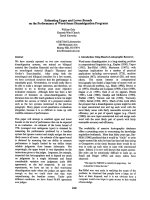
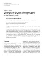
Figure 8. Effective horizontal stiffness versus displacement of different prototype U-FREIs
Fig. 8. Effective horizontal stiffness versus displacement of different prototype U-FREIs
17
Due to rollover deformation, the area of these specimens in contact with the support surfaces
decrease with the increase in horizontal displacement, thus resulting in the reduction in effective
horizontal stiffness. It can be seen from Fig. 8 that at a given displacement, whereas the U-FREI types A
Ngo, V. T. / Journal of Science and Technology in Civil Engineering
these isolators are compared to infer on the influence of shear modulus on isolators. Reduction in
effective horizontal stiffness of U-FREI types A and B with increasing horizontal displacement as
obtained from both experiments and FE analyses is shown in Fig. 8.
Due to rollover deformation, the area of these specimens in contact with the support surfaces
decrease with the increase in horizontal displacement, thus resulting in the reduction in effective
horizontal stiffness. It can be seen from Fig. 8 that at a given displacement, whereas the U-FREI
types A and B are likely to have same area in contact with the supports, the horizontal stiffness of
U-FREI decreases with the decrease in shear modulus. Thus, the decrease in horizontal stiffness of
U-FREI with increasing horizontal displacement is not only due to rollover deformation through the
decrease in area in contact with the supports, but also due shear modulus of isolator.
6. Conclusions
This paper presents experimental as well as numerical analysis of prototype U-FREIs under cyclic
load. Experimental investigations are done up to a displacement limit and finding from FE analysis
are validated. Evaluation of influence of shear modulus on the behavior of U-FREIs are studied. The
concluding remarks are as follows:
- Due to rollover deformation, the effective horizontal stiffness of U-FREIs decreases with the
increase in horizontal displacement, while the equivalent viscous damping increases. The decreases
in effective horizontal stiffness of U-FREIs A(1,2) , B(1,2) as obtained from experimental study are
found to be 39.1%, 37.2% respectively in the displacement range of 20 mm to 80 mm; while those of
U-FREIs A(1,2) , B(1,2) as obtained from FE analysis are found to be 57.2%, 57.0% respectively in the
displacement range of 20 mm to 135 mm.
- Reasonable agreement is found between the findings from experimental and FE analysis at
displacements ranging from 20 mm to 80 mm. FE analysis can be adopted effectively to a very large
range of displacement (135 mm), which may be otherwise difficult in experimental study.
- Reduction in horizontal stiffness of U-FREI with increasing horizontal displacement is due to
both shear modulus and the contact area of the isolator with support surfaces.
Acknowledgements
Author (a former research scholar in IIT Guwahati, Assam, India) would like to acknowledge the
contribution of METCO Pvt. Ltd., Kolkata, India, for manufacturing U-FREI and staffs of Structural
Engineering Laboratory, Department of Civil Engineering, IIT Guwahati, India for their help during
experimental investigation.
References
[1] Kelly, J. M., Takhirov, S. M. (2001). Analytical and experimental study of fiber-reinforced elastometric isolators. PEER Report, 2001/11, Pacific Earthquake Engineering Research Center, University of California,
Berkeley, USA.
[2] Toopchi-Nezhad, H., Tait, M. J., Drysdale, R. G. (2008). Lateral response evaluation of fiber-reinforced
neoprene seismic isolators utilized in an unbonded application. Journal of Structural Engineering, 134
(10):1627–1637.
[3] Strauss, A., Apostolidi, E., Zimmermann, T., Gerhaher, U., Dritsos, S. (2014). Experimental investigations
of fiber and steel reinforced elastomeric bearings: Shear modulus and damping coefficient. Engineering
Structures, 75:402–413.
18
Ngo, V. T. / Journal of Science and Technology in Civil Engineering
[4] Dezfuli, F. H., Alam, M. S. (2014). Performance of carbon fiber-reinforced elastomeric isolators manufactured in a simplified process: experimental investigations. Structural Control and Health Monitoring, 21
(11):1347–1359.
[5] Ngo, V. T., Dutta, A., Deb, S. K. (2017). Evaluation of horizontal stiffness of fibre-reinforced elastomeric
isolators. Earthquake Engineering & Structural Dynamics, 46(11):1747–1767.
[6] Ngo, V. T., Deb, S. K., Dutta, A. (2018). Effect of horizontal loading direction on performance of prototype
square unbonded fibre reinforced elastomeric isolator. Structural Control and Health Monitoring, 25(3):
1–18.
[7] Naeim, F., Kelly, J. M. (1999). Design of seismic isolated structures: from theory to practice. John Wiley
& Sons.
[8] IBC-2000 (2000). International building code. USA.
19